Simple Electrical Modulation Scheme for
Laser Feedback Imaging
Karl Bertling, Member, IEEE, Thomas Taimre, Associate Member, IEEE, Gary Agnew, Member, IEEE,
Yah Leng Lim, Member, IEEE, Paul Dean, Dragan Indjin, Sven Höfling, Senior Member, IEEE,
Robert Weih, Martin Kamp, Michael von Edlinger, Johannes Koeth, Member, IEEE,
and Aleksandar D. Raki´c, Senior Member, IEEE
Abstract— In this paper, we demonstrate a simple square-wave
electrical modulation scheme for imaging with laser feedback
interferometry (LFI). Distinct advantages of this scheme include:
1) the straightforward creation of the modulating signal, even
for high-current lasers and 2) its natural suitability for lock-in
detection. We compare this simple scheme against two
estab-lished imaging modalities for LFI: 1) mechanical modulation
using an optical chopper and 2) the swept-frequency feedback
interferometry approach. The proposed scheme lends itself to
high-frequency modulation, which paves the way for high
frame-rate LFI imaging with no motion artefacts using off-the-shelf
equipment.
Index Terms— Laser feedback, interferometry, semiconductor
lasers.
I. I
NTRODUCTIONE
XPERIMENTALLY simple schemes for high frame-rate
imaging using laser feedback interferometry (LFI)
are of fundamental interest for many applications [1]–[3].
Manuscript received February 16, 2015; revised July 7, 2015 and November 23, 2015; accepted November 29, 2015. Date of publication December 9, 2015; date of current version February 10, 2016. This work was supported in part by the State of Bavaria, in part by the European Cooperation in Science and Technology under Grant BM1205, and in part by the Australian Research Council’s Discovery Projects under Grant DP 120 103703. The work of Y. L. Lim was supported by the Queensland Government’s through the Smart Futures Fellowships Programme. The work of P. Dean was supported by the Engineering and Physical Sciences Research Council, U.K. The work of S. Höfling was supported by the Royal Society and the Wolfson Foundation. The associate editor coordinating the review of this paper and approving it for publication was Dr. Shoushun Chen.
K. Bertling, G. Agnew, Y. L. Lim, and A. D. Raki´c are with the School of Information Technology and Electrical Engineering, University of Queensland, Brisbane, QLD 4072, Australia (e-mail: [email protected]; [email protected]; [email protected]; [email protected]).
T. Taimre is with the School of Mathematics and Physics, The University of Queensland, Brisbane, QLD 4072, Australia (e-mail: [email protected]). P. Dean and D. Indjin are with the School of Electronic and Elec-trical Engineering, University of Leeds, Leeds LS2 9JT, U.K. (e-mail: [email protected]; [email protected]).
S. Höfling is with the School of Physics and Astronomy, University of St Andrews, St Andrews KY16 9SS, U.K., also with Technische Physik, Physikalisches Institut, Universität Würzburg, Würzburg D-97074, Germany, and also with the Wilhelm Conrad Röntgen Research Center for Complex Material Systems, Universität Würzburg, Würzburg D-97074, Germany (e-mail: [email protected]).
R. Weih and M. Kamp are with Technische Physik, Physikalisches Institut, Universität Würzburg, Würzburg D-97074, Germany, and also the Wilhelm Conrad Röntgen Research Center for Complex Material Systems, Universität Würzburg, Würzburg D-97074, Germany (e-mail: robert.weih@ physik.uni-wuerzburg.de; [email protected]).
M. von Edlinger and J. Koeth are with nanoplus GmbH, Gerbrunn 97218, Germany (e-mail: [email protected]; [email protected]).
Digital Object Identifier 10.1109/JSEN.2015.2507184
Most of the LFI imaging techniques (which utilise the
self-mixing effect) proposed to date are limited in achievable
modulation
frequency
(and
consequently
the
imaging
frame-rate) by the mechanical nature of the modulation
scheme or the complexity of the electrical modulation used.
To create the LFI signal some of these methods use an
optical chopper [4], [5], or require longitudinal displacement
of the object being imaged [6]. Mechanical modulation
can also be achieved by using microelectromechanical
devices, thus significantly decreasing the size of the complete
system [7], [8]. Alternatively they require involved electrical
or electro-optical modulation and detection schemes including
frequency shifting of the laser beam by acousto-optic
deflec-tors [9]–[11] or swept-frequency feedback interferometry
with directly modulated lasers [12]–[16]. The LFI signal can
also be detected without additional modulation of the laser
carrier, by measuring the extremely small variations in the
DC signal while scanning [17], [18]. However, the LFI signal
can easily be obscured by fluctuations (a consequence of
motion artefacts) when the scanning is rapid.
To overcome these limitations, we propose an ultimately
simple electrical modulation scheme for LFI imaging using
square-wave modulation of the laser current. Three sets of
experiments were performed on the same imaging target to
compare this simple modulation scheme against two
estab-lished LFI imaging methods. Additional displacement
exper-iments and simulations were carried out to elucidate on the
nature of the observed interference fringes. In all cases,
exper-iments were carried out using a mid-infrared (MIR) interband
cascade laser (ICL) [19], [20]. The extremely simple nature
of the square-wave laser current modulation scheme paves the
way for high frame-rate imaging at high laser driving currents,
from which MIR and THz QCL imaging applications may
benefit significantly [21]–[23].
II. E
XPERIMENTALS
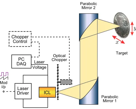
ETUPThe experimental setup of the LFI system can be seen
in Fig. 1. The MIR distributed feedback (DFB) ICL
(
λ
=
3
.
57 µm) used in this study was a design adapted
from [24] and operating characteristics (light–current, current–
voltage curves, and the emission spectrum) were described in
detail in [5]. The device was designed specifically for optical
spectroscopy of organic molecules and exhibits high level of
phase stability and narrow emission linewidth. The package
1558-1748 © 2015 IEEE. Translations and content mining are permitted for academic research only. Personal use is also permitted,
Fig. 1. Schematic of the experimental apparatus used.
used enables highly accurate temperature control making this
laser eminently suitable for comparing different modulation
schemes proposed in this article.
The ICL was kept at a constant temperature of 20
◦C
using a Peltier temperature controller mounted inside the
laser package, and operated at a drive current of 65 mA,
approximately 1.3 I
th(current threshold I
th=
50 mA) with an
output power of about 1.4 mW. The emitted radiation from the
ICL was collimated using a 2 inch diameter, 2 inch focal length
off-axis parabolic reflector and focused normally on the target
using a second identical reflector (giving an optical path length
of 341.6 mm). The voltage signal across the laser terminals
was ac-coupled into a
×
1000 gain differential amplifier and
subsequently fed into a 16-bit PC-based data acquisition card
synchronised with the chopper or signal generator.
The ICL was operated in three different modes: (1)
mechani-cally modulated using an optical chopper; (2) electrimechani-cally
mod-ulated with a square-wave current signal; and (3) electrically
modulated with a saw-tooth current signal. Each measurement
data point (spatial pixel) was obtained using 64 averaged
time-domain waveforms. All experiments were carried out using
a 1 kHz modulation frequency. Imaging experiments were
performed on an Australian 5-cent coin and in the subsequent
displacement experiments an aluminium front surfaced mirror
was used. In all experiments, targets were mounted on a
three-axis computer-controlled translation stage, allowing each to
be displaced along the optical axis of the system (z) or raster
scanned in a plane perpendicular to the optical axis (x –y).
A. Mechanical Modulation Using Optical Chopper
The ICL beam was modulated at 1 kHz with an optical
chopper placed just in front of the output aperture of the laser,
thereby amplitude-modulating the optical feedback which the
laser was experiencing. Two states are present: (1) the chopper
blade is obstructing the beam — the laser is operating with
virtually no feedback; and (2) the beam is transmitted between
the blades and to the external target — the laser is operating
with an external feedback level dictated by the target. These
two states result in two distinct voltage levels across the ICL,
giving rise to a square-wave LFI signal in the time domain.
Fig. 2. Diagram of the three modulation schemes and their resulting LFI signals: (a) optical chopper; (b) square-wave current modulation; and (c) saw-tooth current modulation.
Figure 2(a) shows a representative voltage waveform measured
across the laser terminals using this approach. This waveform
clearly shows two states — the root-mean-square (RMS) of
these waveforms (trimmed to central 90% of values) was used
for image formation.
B. Square-Wave Current Modulation
A square-wave modulation of the laser current was applied
with a frequency of 1 kHz superimposed on the constant laser
drive current with a modulation depth of 1 mA. Square-wave
modulation has a range of advantages in terms of ease of
implementation and the availability of high-speed high-current
off-the-shelf equipment that can be used to implement it.
How-ever, we would like to point out that a number of phenomena
are involved in determining the voltage levels across the laser
at the two current levels used. Firstly, as the laser sensitivity
to feedback changes with bias current [4], [25] in particular
in close to the lasing threshold, this type of modulation
creates the LFI signal corresponding to two different bias
points, in an alternating pattern [see Fig. 2(b)]. Secondly, due
to current-induced frequency shift between these two states,
the laser is essentially operating at two different frequencies
corresponding to two different phase shifts accumulated in
the external cavity, which the laser interferometer converts
into two intensity levels with their corresponding voltages.
One should keep in mind that the feedback-caused voltage
variation is superimposed on the (much bigger) voltage change
caused directly by the changes in laser driving current. All
these phenomena contribute to the observed voltage signal,
with their relative contribution depending on the laser type
and the current levels used. The RMS value of the measured
and trimmed voltage waveform was used for image formation.
C. Saw-Tooth Current Modulation
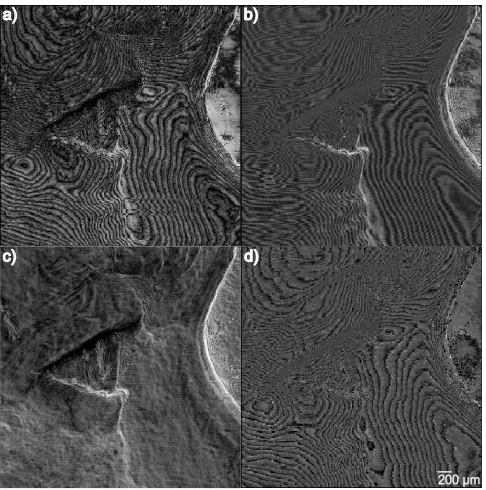
[image:2.612.66.283.55.229.2]Fig. 3. Images of a small region on an Australian 5-cent coin, using the three modulation schemes. a) Optical chopper (RMS). b) Square-wave laser current modulation (RMS). c) Saw-tooth current modulation amplitude-like (peak-to-peak). d) Saw-tooth current modulation phase-like (peak position).
output power of the laser but also induces a linear sweep of
the laser frequency. Figure 2(c) shows a typical waveform from
this modulation scheme as measured across the laser terminals.
The information-bearing portion of the measured waveform is
the signal riding on the saw-tooth — Fig. 2(c) also shows the
same waveform after the ramp has been removed (‘negatised’)
allowing the interferometric fringes in the waveform to be
clearly seen. This waveform contains information about target
reflectivity and the phase-shift on reflection [15]. Therefore,
two images can be obtained concurrently; one being
represen-tative of the strength of reflection at any given point, and the
other corresponding to the phase-shift on reflection at the same
point. The first of these images was obtained by extracting
the peak-to-peak voltage of the negatised and trimmed signal,
while the position of the last peak relative to the modulation
period was used to obtain the phase image.
III. R
ESULTS ANDD
ISCUSSIONA. Imaging With Laser Feedback Interferometry
[image:3.612.313.546.58.406.2]The three modulation schemes were used to image the same
1
.
5
×
1
.
5 mm
2region (with 5
μ
m pitch) on the obverse of
an Australian 5-cent coin. The common current bias point for
the three schemes was 65 mA, near to where the maximum
LFI signal was observed using the mechanical modulation
scheme. Figure 3 shows the results of imaging for the target
with each of the three schemes. In each of the four images,
the three dimensional nature of the target is clearly visible.
Figures 3(a), 3(b), and 3(d) show interferometric fringes
arising from the changing surface profile of the target on the
scale of similar order as the laser wavelength. In Fig. 3(c)
these interferometric fringes are conspicuously absent due to
Fig. 4. Signal strength each modulation scheme over displacement: simu-lated (left) and experimental (right, biased at 65 mA) results for the three modulation schemes. a) Optical chopper. b) Square-wave current modulation (1 mA modulation depth). c) Saw-tooth current modulation (amplitude-like). d) Saw-tooth current modulation (phase-like).
the amplitude-like nature of this representation; the phase
information has been decoupled and is shown in Fig. 3(d).
B. Displacement Characteristics of the Three Schemes
with high reflectivity when the beam passes between chopper
blades to the mirror at two distances from the laser. This
was implemented by changing the value of the feedback
parameter C (a commonly used quantity for characterizing
feedback levels [27]) between a low (C
=
0
.
001) and a high
(C
=
1) value, and using two distances given by the geometry
of the experimental setup. A clear match between simulation
and experiment was observed.
Square-wave current modulation was captured in simulation
by periodically switching between two different operating
frequencies at two different voltage levels (corresponding to
the two different driving currents). It is interesting to note
that the observed change in RMS of the simulated signal with
displacement was modelled solely through the difference in
the transmission phase accumulated in the external cavity at
each of the two operating frequencies and the change in laser
sensitivity to feedback with the driving current was ignored.
The effect of saw-tooth current modulation on the negatised
LFI signal was included in simulation as a linear frequency
chirp over the modulation period as dictated by the frequency
modulation coefficient of the laser. For each position of the
target, this frequency chirp results in two or more ripples
(peaks) in the LFI signal waveform — corresponding to
a change in transmission phase of greater than 4
π
. The
position of these peaks relative to the modulation waveform
was determined by the length of the external cavity. As the
target was linearly displaced, there was a corresponding linear
change in the transmission phase, which was clearly captured
[Fig. 4(d)] both in experiment and simulation.
On the other hand, the peak-to-peak amplitude of this
saw-tooth current modulation signal should not change
with displacement, as properly reflected in our simulation
[Fig. 4(c)]. The experimental signal displays traces of the
phase information seeping into the peak-to-peak amplitude.
This explains the presence of the interference fringes in
Figs 3(a), 3(b), and 3(d) and their (almost complete) absence
in Fig. 3(c).
C. Discussion
Both experiment and simulation show that the effects
leading to the image formation were the change in the external
cavity length and the change in the effective reflectivity [in
this case the reflectivity of the target (5-cent coin) is changing
due to change in angle and roughness at different points
where the beam interrogates the surface]. The displacement
experiment, where the reflectivity of the target was kept
constant, clearly separates the two effects. For the first two
modulation schemes [see Figs. 4(a) and (b)] the amplitude
of the LFI signal depends on the displacement of the target;
in the third case, due to the FM nature of the modulation
scheme, it is the phase, not the amplitude of the LFI signal
that contains the information about the displacement of the
target. In all three cases, interference fringes (caused by the
phase wrapping) are observable in the obtained images [see
Figs. 4(c) and (d)]. The change in the effective reflectivity of
the target additionally modulates the strength of the signal, and
was clearly separated from the phase information in Fig. 3(c).
Each of the three modulation schemes has some comparative
advantages. The mechanical modulation through the optical
chopper produces simple output signal — lending itself to
straightforward lock-in detection — and results in the
great-est contrast with displacement, but has the modulation
fre-quency limited by mechanical considerations. At high speeds
it also introduces spurious mechanical vibrations and periodic
changes in the refractive index of the air that will be detected
by the system [28].
The square-wave current modulation can be implemented
at high frequencies for high-current lasers (for example THz
QCLs) — limited only by the characteristics of the laser
being used — whilst retaining natural suitability for lock-in
detection. Moreover, as no mechanical modulation is required,
this scheme is more compact, requires fewer elements, and
avoids any problems resulting from mechanical vibrations.
Finally, the saw-tooth current modulation results in
two distinct concurrently captured images — each bearing
complementary information about the target. However, the
generation and detection of the modulating current waveforms
and resulting voltage signals is considerably more involved,
especially for high current lasers.
IV. C
ONCLUSIONWe have proposed a very simple square-wave electrical
modulation scheme for imaging with LFI. The simplicity of
the modulating current waveform lends itself to high frequency
modulation with high current lasers and detection using
off-the-shelf equipment. The proposed scheme compares well with
established LFI imaging modalities.
R
EFERENCES[1] G. Giuliani, M. Norgia, S. Donati, and T. Bosch, “Laser diode self-mixing technique for sensing applications,” J. Opt. A, Pure Appl. Opt., vol. 4, no. 6, pp. S283–S294, 2002.
[2] S. Donati, “Developing self-mixing interferometry for instrumentation and measurements,” Laser Photon. Rev., vol. 6, no. 3, pp. 393–417, 2012.
[3] T. Taimre, M. Nikoli´c, K. Bertling, Y. L. Lim, T. Bosch, and A. D. Raki´c, “Laser feedback interferometry: A tutorial on the self-mixing effect for coherent sensing,” Adv. Opt. Photon., vol. 7, no. 3, pp. 570–631, 2015.
[4] P. Dean et al., “Terahertz imaging through self-mixing in a quantum cascade laser,” Opt. Lett., vol. 36, no. 13, pp. 2587–2589, 2011. [5] K. Bertling et al., “Demonstration of the self-mixing effect in
inter-band cascade lasers,” Appl. Phys. Lett., vol. 103, no. 23, p. 231107, 2013.
[6] P. Dean et al., “Coherent three-dimensional terahertz imaging through self-mixing in a quantum cascade laser,” Appl. Phys. Lett., vol. 103, no. 18, p. 181112, 2013.
[7] V. Annovazzi-Lodi, S. Merlo, and M. Norgia, “Measurements on a micromachined silicon gyroscope by feedback interferometry,” IEEE/ASME Trans. Mechatronics, vol. 6, no. 1, pp. 1–6, Mar. 2001. [8] V. Annovazzi-Lodi, S. Merlo, and M. Norgia, “Characterization of
silicon microstructures by feedback interferometry,” J. Opt. A, Pure Appl. Opt., vol. 4, no. 6, pp. S311–S317, 2002.
[9] R. Day, E. Lacot, F. Stoeckel, and B. Berge, “Three-dimensional sensing based on a dynamically focused laser optical feedback imaging technique,” Appl. Opt., vol. 40, no. 12, pp. 1921–1924, 2001. [10] O. Jacquin, S. Heidmann, E. Lacot, and O. Hugon, “Self-aligned
setup for laser optical feedback imaging insensitive to parasitic optical feedback,” Appl. Opt., vol. 48, no. 1, pp. 64–68, Jan. 2009.
[12] S. Shinohara, H. Yoshida, H. Ikeda, K. Nishide, and M. Sumi, “Compact and high-precision range finder with wide dynamic range and its application,” IEEE Trans. Instrum. Meas., vol. 41, no. 1, pp. 40–44, Feb. 1992.
[13] T. Bosch, N. Servagent, R. Chellali, and M. Lescure, “Three-dimensional object construction using a self-mixing type scanning laser range finder,” IEEE Trans. Instrum. Meas., vol. 47, no. 5, pp. 1326–1329, Oct. 1998. [14] E. Gagnon and J.-F. Rivest, “Laser range imaging using the self-mixing effect in a laser diode,” IEEE Trans. Instrum. Meas., vol. 48, no. 3, pp. 693–699, Jun. 1999.
[15] A. D. Raki´c et al., “Swept-frequency feedback interferometry using ter-ahertz frequency QCLs: A method for imaging and materials analysis,” Opt. Exp., vol. 21, no. 19, pp. 22194–22205, 2013.
[16] J. Keeley et al., “Three-dimensional terahertz imaging using swept-frequency feedback interferometry with a quantum cascade laser,” Opt. Lett., vol. 40, no. 6, pp. 994–997, 2015.
[17] R. Juškaitis, N. P. Rea, and T. Wilson, “Semiconductor laser confocal microscopy,” Appl. Opt., vol. 33, no. 4, pp. 578–584, 1994.
[18] M. Wang and G. Lai, “Self-mixing microscopic interferometer for the measurement of microprofile,” Opt. Commun., vol. 238, nos. 4–6, pp. 237–244, 2004.
[19] R. Weih, M. Kamp, and S. Höfling, “Interband cascade lasers with room temperature threshold current densities below 100 A/cm2,” Appl. Phys. Lett., vol. 102, no. 23, p. 231123, 2013.
[20] I. Vurgaftman et al., “Interband cascade lasers,” J. Phys. D, Appl. Phys., vol. 48, no. 12, p. 123001, 2015.
[21] F. P. Mezzapesa et al., “Continuous-wave reflection imaging using optical feedback interferometry in terahertz and mid-infrared quantum cascade lasers,” IEEE Trans. Terahertz Sci. Technol., vol. 4, no. 5, pp. 631–633, Sep. 2014.
[22] Y. L. Lim et al., “High-contrast coherent terahertz imaging of porcine tissue via swept-frequency feedback interferometry,” Biomed. Opt. Exp., vol. 5, no. 11, pp. 3981–3989, Nov. 2014.
[23] P. Dean et al., “Terahertz imaging using quantum cascade lasers— A review of systems and applications,” J. Phys. D, Appl. Phys., vol. 47, no. 37, p. 374008, 2014.
[24] I. Vurgaftman et al., “Rebalancing of internally generated carriers for mid-infrared interband cascade lasers with very low power consump-tion,” Nature Commun., vol. 2, p. 585, Dec. 2011.
[25] K. B. Rochford and A. H. Rose, “Simultaneous laser-diode emission and detection for fiber-optic sensor applications,” Opt. Lett., vol. 20, no. 20, pp. 2105–2107, 1995.
[26] R. Kliese et al., “Solving self-mixing equations for arbitrary feedback levels: A concise algorithm,” Appl. Opt., vol. 53, no. 17, pp. 3723–3736, 2014.
[27] K. Petermann, Laser Diode Modulation and Noise. Boston, MA, USA: Kluwer, 1991.
[28] K. Bertling et al., “Imaging of acoustic fields using optical feedback interferometry,” Opt. Exp., vol. 22, no. 24, pp. 30346–30356, 2014.
Karl Bertling (S’06–M’12) received the B.E. degree
in electrical engineering, the B.Sc. degree in physics, the M.Phil. degree in electrical engineering, and the Ph.D. degree in electrical engineering from The University of Queensland, in 2003, 2006, and 2012, respectively. He has contributed to the body of knowledge for this technique, in visible, near-IR, mid-near-IR, and terahertz semiconductor lasers. His current research interest are imaging and sensing via laser feedback interferometry (utilizing the self-mixing effect).
Thomas Taimre received the B.Sc. degree in
mathematics and statistics, the B.Sc. (Hons.) degree in statistics, and the Ph.D. degree in mathematics from The University of Queensland, Australia, in 2003, 2004, and 2009, respectively. He is currently a Lecturer of Mathematics and Statistics with The University of Queensland. He has co-authored the book entitled Handbook of Monte Carlo Methods, which provides a hands-on guide to the theory, algorithms, techniques, and applications of Monte Carlo methods. His current research is at the interface of probability theory, computer simulation, and mathematical optimization with biological and other scientific, engineering, and finance disciplines, including within laser feedback interferometry.
Gary Agnew (M’93) received the B.Sc. and M.Sc.
degrees in electrical engineering from the University of the Witwatersrand, Johannesburg, South Africa, in 1985 and 1990, respectively. He is currently pursuing the Ph.D. degree with The University of Queensland, Australia. He has held a variety of research positions in the instrumentation industry, working on microwave, photonic, and nucleonic sensor technology. His research interests include modeling terahertz quantum cascade lasers.
Yah Leng Lim received the B.Eng. and Ph.D. degrees in electrical
engi-neering from The University of Queensland, Brisbane, Australia, in 2001 and 2011, respectively. From 2002 to 2005, he joined Philips Optical Storage, Singapore, as an R&D Engineer, working on the integration of optical and sensor technologies in optical storage systems. He currently holds a Smart Futures Fellowship funded by the Queensland Government, focusing on the development of LFI imaging systems for the early detection of skin cancers.
Paul Dean received the M.Phys. (Hons.) degree in physics and the Ph.D.
degree in laser physics from the University of Manchester, Manchester, U.K., 2001 and 2005, respectively. In 2005, he was appointed as a Post-Doctoral Research Associate with the Institute of Microwaves and Photonics, School of Electronic and Electrical Engineering, University of Leeds, Leeds, U.K. His current research interests include terahertz optoelectronics, quantum cascade lasers, and terahertz imaging techniques. He received a fellowship from the Engineering and Physical Sciences Research Council (U.K.) in 2011.
Dragan Indjin was born in Zemun, Yugoslavia,
in 1963. He received the B.S., M.S., and Ph.D. degrees in electrical engineering from the University of Belgrade, Belgrade, Yugoslavia, in 1988, 1993, and 1996, respectively.
He joined the Faculty of Electrical Engineering, University of Belgrade, in 1989, where he later became an Associate Professor. Since 2001, he has been with the Institute of Microwaves and Photon-ics, School of Electronic and Electrical Engineer-ing, University of Leeds, Leeds, U.K., where he is currently a Reader (Associate Professor) in Optoelectronics and Nanoscale Electronics. He is currently focused on applications of quantum-cascade lasers and interband cascade lasers for sensing and imaging applications. His research interests include the electronic structures, optical and transport properties, optimization and design of quantum wells, superlattices, quantum-cascade lasers, and quantum-well infrared photodetectors from near- to far-infrared and terahertz spectral ranges.
Dr. Indjin was a recipient of the prestigious Academic Fellowship from the Institute of Microwaves and Photonics, School of Electronic and Electrical Engineering, University of Leeds, in 2005. He is currently a Coordinator of major international projects on infrared and terahertz imaging and sensing for medical and security applications.
Sven Höfling (M’04–SM’13) was born in 1976.
He received the Diploma degree in applied physics from the University of Applied Science, Coburg, and the Ph.D. degree from the Universität Würzburg, Germany. He was with the Fraunhofer Institute of Applied Solid-State Physics, Freiburg, Germany, from 2001 to 2002, working on blue and white light emitting diodes. In 2003, he joined the Universität Würzburg for his Ph.D. work on single mode emit-ting GaAs/AlGaAs quantum cascade lasers. From 2006 to 2013, he was the Head of the Optoelectronic Materials and Devices Group, Technische Physik, Universität Würzburg. He is currently a Professor of Physics with the Universität Würzburg, and the University of St Andrews, U.K.
His research interests include the design, fabrication, and characterization of low-dimensional electronic and photonic nanostructures, including quantum wells and quantum dots, organic semiconductors, high-quality factor micro-cavities, photonic crystal devices, semiconductor lasers, organic optoelectron-ics, and transition metal oxides.
Robert Weih was born in 1985. He received the Diploma degree from the
Universität Würzburg in 2011. He was working on mid infrared interband cas-cade lasers as a Ph.D. student with the Chair of Technische Physik, Universität Würzburg. His research interests include the growth and characterization of III–V semiconductors and the development of semiconductor devices, such as lasers and detectors. He is member of the German Physical Society.
Martin Kamp received the master’s degree from
Stony Brook University, Stony Brook, NY, USA, in 1995, and the Ph.D. degree from the Universität Würzburg, Würzburg, Germany, in 2003, for his work on laterally coupled distributed feedback lasers. He joined the Department of Technische Physik in 1996. From 2010 to 2015, he was the Interims Chair of the Department of Technische Physik. Since then, he is responsible for the nanofabrication and nanophotonic research with the Department of Technische Physik and the Gottfried-Landwehr Laboratory for Nanotechnology, Universität Würzburg. He has authored or co-authored over 250 papers relating to semiconductor nanostructures, opto- and nanoelectronic devices, and semiconductor spectroscopy.
His current research interests include low-dimensional electronic and photonic semiconductor structures and the development of semiconductor-based optical quantum information processing and interband cascade lasers.
Dr. Kamp is a member of the German Physical Society.
Michael von Edlinger was born in Bamberg, Germany, in 1982. He received
the degree from the University of Würzburg with a focus on low-emitting ceramics based on TiO2 in 2008. He started to work on his Ph.D. thesis at nanoplus in 2009. The main topic of his thesis is the design and fabrication of monolithic and widely tunable interband cascade laser sources for trace gas detection.
Johannes Koeth received the degree in physics from
the Universität Würzburg with studies on molecular beam epitaxy (MBE) and optical properties of GaN in 1996. During his Ph.D., he worked on MBE of lasers in the AlGaSb system in the wavelength range between 1.5 and 2.0 µm. One of the main topics of his thesis was the investigation of GaSb-based emit-ters on GaAs substrates. He realized, e.g., the first GaSb edge emitting laser diodes based on GaAs and optically pumped Ga(Al)Sb/AlSb VCSELs, both at 1.5 µm. In addition, he developed and characterized antimonide-based DFB lasers in the 2-µm range. In 1998, he participated to the creation of nanoplus nanosystems and technologies GmbH and has been the CEO of the company ever since.
Aleksandar D. Raki´c (M’93–SM’10) leads the