UNIVERSITI TEKNIKAL MALAYSIA MELAKA
Development of Power Generator System using Thermal source
from car
This report submitted in accordance with requirement of the Universiti Teknikal Malaysia Melaka (UTeM) for the Bachelor’s Degree in Engineering Technology (Bachelor's Degree in Electronics Engineering Technology (Industrial Electronic)
with Honours) (Hons.)
by
STUDENT NAME : NG KAH HOE
MATRIX NUMBER : B071310499
IC NUMBER : 930505065303
UNIVERSITI TEKNIKAL MALAYSIA MELAKA
BORANG PENGESAHAN STATUS LAPORAN PROJEK SARJANA MUDA
TAJUK:
Development of Power Generator System using Thermal source
from car
SESI PENGAJIAN: 2016/17 Semester 2
Saya NG KAH HOE
mengaku membenarkan Laporan PSM ini disimpan di Perpustakaan Universiti Teknikal Malaysia Melaka (UTeM) dengan syarat-syarat kegunaan seperti berikut:
1. Laporan PSM adalah hak milik Universiti Teknikal Malaysia Melaka dan penulis. 2. Perpustakaan Universiti Teknikal Malaysia Melaka dibenarkan membuat salinan
untuk tujuan pengajian sahaja dengan izin penulis.
3. Perpustakaan dibenarkan membuat salinan laporan PSM ini sebagai bahan pertukaran antara institusi pengajian tinggi.
4. **Sila tandakan ( )
SULIT
TERHAD
TIDAK TERHAD
(Mengandungi maklumat yang berdarjah keselamatan atau kepentingan Malaysia sebagaimana yang termaktub dalam AKTA RAHSIA RASMI 1972)
(Mengandungi maklumat TERHAD yang telah ditentukan oleh organisasi/badan di mana penyelidikan dijalankan)
Alamat Tetap:
Tarikh: ________________________
Disahkan oleh:
Cop Rasmi:
Tarikh: _______________________
DECLARATION
I hereby, declared this report entitled ―Development of Power Generator
System using Thermal source from car‖ is the results of my own research
except as cited in references.
Signature : ……….
Author’s Name : ………
APPROVAL
This report is submitted to the Faculty of Engineering Technology of UTeM as a partial fulfillment of the requirements for the degree of Bachelor of Engineering Technology (Department of Electronics & Computer Engineering Technology) (Bachelor's Degree in Electronics Engineering Technology (Industrial Electronics) with Honours). The member of the supervisory is as follow:
i
ABSTRAK
Laporan ini menunjukkan pembangunan sistem penghasilan tenaga elektrik dalam kereta dengan mengunakan tenaga haba. Terdapat banyak tenaga yang terhasil di sekeliling termasuklah dalam sistem operasi kereta. Oleh itu, tercetus idea untuk menggunakan semula tenaga haba yang menghasilkan sumber tenaga elektrik untuk digunakan kepada peranti kereta. Tenega haba akan dimanfaatkan dengan projek pembangunan sistem penghasilan tenaga elektrik dalam kereta dengan mengunakan tenaga haba dibangunkan
Sistem Penjimatan tenaga elektrik dalam kereta mengunakan pendekatan peltier yang menukarkan tenaga haba kepada tenaga elektrik semasa berlakunya perbezaan suhu. DC-DC pengubah boost digunakan untuk mengamplikasikan voltan daripada peltier untuk dibekalkan kepada peranti kereta.
ii
ABSTRACT
This report presents the Development of Power Generator System using Thermal source from car. Wasted energy is occurred in our surrounding all over the world including in a car operating system. Therefore, an idea of reusing the thermal and generate electric to supply car devices is occured. In order to benefit wasted energy, a power generator system to reuse the thermal source is an essential to be installed.
The approach of power generator system is using a thermoelectric generator to convert heat source from a car to electrical source when different temperature occur. A DC-DC boost converter is used to amplify the voltage from the converted voltage and supply to the car devices.
iii
DEDICATION
I’m dedicating this project to my beloved parents who have raising me, giving full of caring and love in my life. This project is created as a way of looking back on my life
iv
ACKNOWLEDGEMENT
I would like to thank Miss Siti Halma Binti Johari as my supervisor for her guidance on completing this project. I would also like to thank all my friends that support me during working on this project.
All praise to the god that I belief for bestowing me with health and opportunity to gain this treasure of knowledge and experience to complete this project. First and foremost, we would like to thank to our Universiti Teknikal Malaysia Melaka (UTeM) for helping me funding this project.
Besides, we would like to thank to Universiti Teknikal Malaysia Melaka (UTeM) especially to the Department of Electronics & Computer Engineering Technology (JTKEK), Faculty of Engineering Technology (FTK) for providing us with good environment and facilities to complete this project. Thanks also to the Perpustakaan Universiti Teknikal Malaysia Melaka (UTeM) librarian and related staff for providing us valuable information throughout the project.
v
TABLE OF CONTENT
Abstrak i
Abstract ii
Dedication iii
Acknowledgement iv
Table of Content v-vi
List of Tables vii
List of Figures viii-ix
List Abbreviations, Symbols and Nomenclatures x
CHAPTER 1: INTRODUCTION
1.1 Project Background 1-6
1.2 Problem Statement 7
1.3 Objective 8
1.4 Scope 9
CHAPTER 2: LITERATURE REVIEW
2.1 A Brief History of Thermoelectric 10-12
2.2 Thermoelectric Module 13-14
2.2.1 Peltier Module 15-16
2.2.2 Advantage of Peltier Module 17
2.2.3 Disadvantage of Peltier Module 18
2.2.4 Identification for Peltier 19
2.3 DC-DC Boost Converter 20-23
2.4 The Construction Diagram 24-25
2.5 Heat sources from car 25-28
CHAPTER 3: METHODOLOGY
vi
3.2 Project Planning 30-31
3.3 Research of the project 32
3.4 Choose the suitable devices and equipment 32
3.4.1 Hardware : Peltier TEC1-12706 32
3.5 Process Implement and Troubleshoot Problems 33
3.6 Report Writing 34
CHAPTER 4 : RESULT AND DISCUSSION
4.1 Introduction 35
4.2 The Experiment Results 35-44
CHAPTER 5: CONCLUSION AND RECOMMENDATION
5.1 Introduction 45
5.2 Conclusion of the project 46
5.3 Recommendation for Future Works 47
REFERENCES 48-49
APPENDICES 50
i. DATASHEET OF PELTIER TE-127-1.4-1.15 51-53
vii
LIST OF TABLES
2.1 Summary of thermoelectric effect 12
2.2 Energy allocation for petrol in percentage (%) 26
4.1 Temperature data from the heat shield of exhaust manifold 36
4.2 Input Voltage (V) against Time(s) 38
4.3 Input Voltage (V) against Temperatures (ᵒC) 38
4.4 Input Current (mA) against Time (s) 39
4.5 Input Current (mA) against Temperatures (ᵒC) 39
4.6 Output Voltage (V) against Time (s) 40
4.7 Output Voltage (V) against Temperature (ᵒC) 41
4.8 Output Current (mA) against Time (s) 41
viii
LIST OF FIGURES
1.1 Energy transfer with low efficiency 1
1.2 Energy loss of a car 2
1.3 Seebeck Effect 4
1.4 Peltier Effect 5
1.5 Peltier Module 5
1.6 Sample Circuit of Boost Converter 6
2.1 Thomas Johann Seebeck 10
2.2 Instrument use by Seebeck to observe the deflecting compass needle
11
2.3 Schematic of a Thermoelectric Module 13
2.4 Thermoelectric Generator Construction 14
2.5 Peltier Module 15
2.6 The arrangement of Thermoelectric Module in Peltier 16 2.7 Electrical and Thermal Connectivity of Thermoelectric couples
for each module
16
2.8 A sample of peltier module, ID:TEC1-12706 19
2.9 Continuous Conduction Mode of a Boost Converter 20 2.10 Discontinuous Conduction Mode of a Boost Converter 20
2.11 Early stage of Construction Circuit 24
2.12 The Construction Circuit 24
2.13 Heat sources that come from car 26
2.14 The Place of Exhaust Manifold at the Exhaust System 27
2.15 Construction to get the Temperature Data 27
2.16 Sample of taking the temperature data using UT300A 28
3.1 Procedure for doing all task for the project 31
ix
4.1 Average Temperatures on Exhaust Manifold 37
4.2 The construction circuit of Smart Conversion Power Generator 37
4.3 Input Voltage (V) against Time(s) 38
4.4 Input Voltage (V) against Temperature (ᵒC) 38
4.5 Input Current (mA) against Time(s) 39
4.6 Input Current (mA) against Temperature (ᵒC). 40
4.7 Output Voltage (V) against Time (s) 40
4.8 Output Voltage (V) against Temperature (ᵒC) 41
4.9 Output Current (mA) against Time (s) 42
4.10 Output Current (mA) against Temperature (ᵒC). 42
x
LIST OF ABBREVIATIONS, SYMBOLS AND
NOMENCLATURE
L - Inductor value
C - Capacitor value
- Output Voltage
- Input Voltage
- Maximum Inductor value
- Changes of inductor value
- Changes of Maximum Output Voltage
D - Duty Cycle
- Voltage of Inductor
- The rate of changes of current in Inductor
- Current Changes of Inductor when switch is open
- Current Changes of Inductor when switch is close
T - Period
- Period when switch is close
- Input Power
- Output Power - Resistance value
- Current value in Inductor
1
Chapter 1 :
Introduction
1.1 Project Background
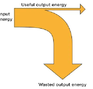
[image:15.612.272.425.516.663.2]Energy cannot be create or destroy but it can be transfer into many different forms. Whenever energy is transfer, there is only a small amount will transfer into useful energy that needed and the rest of the energy is transfer into non-wanted form where it does not help us achieve our aims, so the non-wanted energy is wasted. Eventually the energies end up being transferred to the surrounding, which become warmer and the wasted energy spreads out so much that it becomes hard to reuse it. Since mostly energy is transfer to the surroundings, therefore the most common form of wasted energy is heat. Figure 1.1 represents the energy transfer with low efficiency.
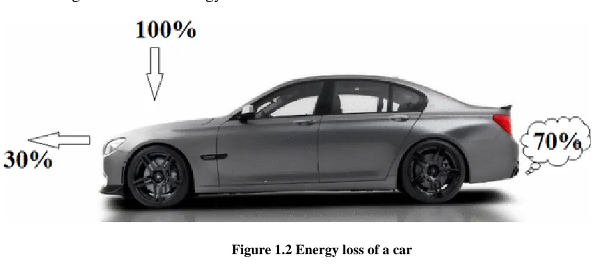
2 Heat energy is spread out from car when car is functioning. Car is a common vehicle which use in transportation. It functions is to transport something from a place to a destination using less time and energy. Nowadays, cars are propelled by an internal combustion engine where input energy is fueled by gasoline or petrol and it will combust to supply the energy to move the car. In scientific terms, a car is an energy converter which can be elaborate as a machine that assimilate energy from fuel and turns it into mechanical energy to move wheels and gears. Due to the number of vehicles and distances driven by those vehicles continue to grow, it is resulting an increase of petroleum consumption and fuel efficiency. Waste heat is produce from the process involved in conversion of fuel energy to mechanical or electrical energy [1]. When the engine start working, the mechanical energy converted to kinetic energy and the car will move consistently as long as petrol is consistently supplied. In the transfer process, the energy is transfer to many types of energy and mostly energy is been wasted. Figure 1.2 shows energy loss of a car.
Figure 1.2 Energy loss of a car
3 mechanical energy, but disperses to the environment as waste heat [2]. Therefore, it’s a huge amount of waste in the process of the car works.
For vehicle which is using petrol as fuel, there is fuel's energy lost in the internal combustion engine. These engines are quite inefficient at the conversion processes, energy lost due to many factor such as engine friction and wasted heat energy spread from pumping air to the engine for the combustion process.
Besides that, there are idling losses which is lost to idling at the traffic light. When a vehicle comes to a stop, the engine stops the combustion process and when traffic light becomes green, the engine needs to be restart and cause more energy consumption [3].
A vehicle must spend more energy to remove air out of the way as it goes down the road. As the air resister lower at lower speed, it consumes less energy and more as speed increases. The air resistance is related to the vehicle's shape. Smoother vehicle shapes can reduce air resistance significantly. Furthermore, there is also friction for a car against the road. To move forward, a vehicle's drivetrain must provide enough energy to overcome the vehicle's inertia, which is directly related to its weight. The less a vehicle weights, the less energy it takes to move it. In addition, any time the user use the brakes, energy is used to overcome the inertia.
4 effect. Thermoelectric effect is the direct conversion of temperature differences to electric voltage and vice versa.
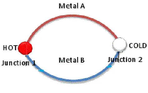
[image:18.612.210.447.300.450.2]Figure 1.3 shows the Seebeck effect experiment that is carried out by Thomas Johann Seebeck in 1821. This experiment is discovered by observing a compass needle that deflected when a closed loop was form using two different metals or semiconductors. Thomas Johann Seebeck believed that this happen because of the magnetism induced by the difference of temperatures. Therefore, Seebeck effect is defined as a phenomenon in which a temperature difference between two dissimilar semiconductors produce a voltage between the two points.
Figure 1.3 Seebeck Effect
5
Figure 1.4 Peltier Effects
Peltier is a device that implies Peltier effect that has two plates which are cold and hot plate. This Peltier device is named as heat pump because it does not create heat or cold and it transfers the heat from one side to another side. Therefore, it is also called thermo-electric generator.
A typical thermoelectric generator will consist of an array of p- and n- type semiconductor elements that act as the two dissimilar conductors. The array of elements is soldered between two ceramic plates, which will places as electrically in series and thermally in parallel [5]. Figure 1.5, it shows that the peltier module has both side which is cold side and hot side and the arrangement of thermoelectric module.
[image:19.612.188.465.469.662.2]6 . The hot side is connected to the heat sink by dissipating the heat to the surrounding. Therefore, in the project, peltier is the main devices to convert the heat energy that spread from car to electric energy to apply in the application.
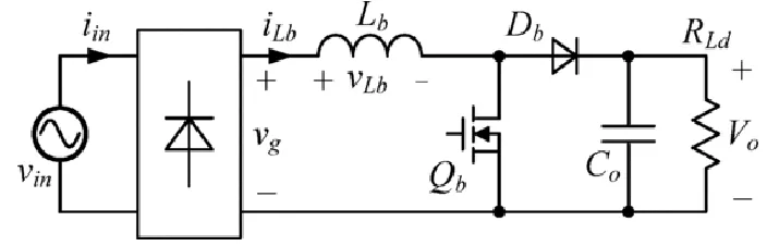
[image:20.612.149.501.236.349.2]A boost converter or step-up converter is used to amplify lower input voltage to higher output voltage. In the boost converter circuit, when switch is closed, the load gets voltage supply which charges through the current passing through the inductor and when switch is open, the load gets supply from the input stage and the inductor. Figure 1.6 shows an example of boost converter.
Figure 1.6 Sample Circuit of Boost Converter
The basic working principles of DC-DC boost converter operate in two modes which are Continuous Conduction Mode and Discontinuous Conduction Mode. For low-power applications, converters are often operated in the discontinuous conduction mode, while high-power applications operate in the continuous conduction mode [6].
7 1.2 Problem Statement
There are much usable energies that usable in our normal life style but most of the energy will be ignore. Thermal energy are one of the energy that spread from car but the energy is not been used for any function. Smart Conversion Power Generator is to use the thermal energy that spread from car, convert it to electric and supply to related devices. There are some problems when research is found about this title. The DC-DC converter converts the thermal energy to electric energy using DC-DC converter. The output voltage is unstable because it might produce the voltage that not in the desire range. Smart Conversion Power Generator need a stable and fix voltage range so that it maintains the wellness of the devices. Besides that, a way to test the temperature data that spread by the car is needed. The temperature data will have substantial change and hard to record the data. The device must be mobility and can receive high temperature data. Next, the design of the project has to cover two different temperature which are low temperature and high temperature. The resource of high temperature will be places near car exhaust manifold since it was the heat output of an engine. The resource of the low temperature plate should face outer site of car because the air will pass by the car and obtain a lower temperature when a car move. The design of the project has to be studied.
8
1.3 Objective
The objective of this project are :
i. To study the working principle of peltier and DC-DC boost converter.
ii. To implement a new power generator system by reusing the wasted thermal energy that spread from car.
9
1.4 Scope
10
CHAPTER 2
LITERATURE REVIEW
2.1 A Brief History of Thermoelectric
[image:24.612.290.363.582.681.2]In the year 1820, the study of thermoelectric began when a German physicist Thomas Johann Seebeck that shown in Figure 2.1 found a circuit at the junctions of two different types of metals with different temperatures would deflect compass magnet which is shown in Figure 2.2 at the next page. At the early stage, Seebeck believed this was due to magnetic polarization of dissimilar metals and termed it the thermo magnetism. However, it was quickly realized that a thermoelectric force induced an electrical current, which by Ampere’s law deflects the magnet. This shows that an electric field was created between two metals due to the magnetism induced by the temperature differences and deflected the needle.