UNIVERSITI TEKNIKAL MALAYSIA MELAKA
DEVELOPMENT OF MEASURING DEVICE WITH MEMORY
USING MICROCONTROLLER
This report submitted in accordance with the requirement of the Universiti Teknikal Malaysia Melaka (UTeM) for the Bachelor of Electrical Engineering
Technology (Robotic and Automation) with Honours.
by
UZAIR BIN MOHD NOR AZAM B071310608
940307 – 01 - 6163
FACULTY OF ENGINEERING TECHNOLOGY 2016
UNIVERSITI TEKNIKAL MALAYSIA MELAKA
BORANG PENGESAHAN STATUS LAPORAN PROJEK SARJANA MUDA
TAJUK: Development of Measuring Device With Memory Using Microcontroller
SESI PENGAJIAN: 2016/17 Semester 2
Saya UZAIR BIN MOHD NOR AZAM
mengaku membenarkan Laporan PSM ini disimpan di Perpustakaan Universiti Teknikal Malaysia Melaka (UTeM) dengan syarat-syarat kegunaan seperti berikut:
1. Laporan PSM adalah hak milik Universiti Teknikal Malaysia Melaka dan penulis. 2. Perpustakaan Universiti Teknikal Malaysia Melaka dibenarkan membuat salinan
untuk tujuan pengajian sahaja dengan izin penulis.
3. Perpustakaan dibenarkan membuat salinan laporan PSM ini sebagai bahan pertukaran antara institusi pengajian tinggi.
4. **Sila tandakan ( )
SULIT
TERHAD
TIDAK TERHAD
(Mengandungi maklumat yang berdarjah keselamatan atau kepentingan Malaysia sebagaimana yang termaktub dalam AKTA RAHSIA RASMI 1972)
(Mengandungi maklumat TERHAD yang telah ditentukan oleh organisasi/badan di mana penyelidikan dijalankan)
Alamat Tetap:
NO. 131 Jalan Anggerik 4
Taman Kulai Utama
Kulai, Johor
Tarikh: ________________________
Tarikh: ________________________
Disahkan oleh:
Cop Rasmi:
Tarikh: _______________________
Tarikh: _______________________
DECLARATION
I hereby, declared this report entitled “Development of Measuring Device With Memory Using Microcontroller” is the results of my own research except as cited
in references.
Signature : ……….
Author’s Name : ………
APPROVAL
This report is submitted to the Faculty of Engineering Technology of UTeM as a partial fulfillment of the requirements for the degree of Bachelor of Electrical Engineering Technology (Robotic and Automation) with Honours. The member of the supervisory is as follow:
i
ABSTRAK
ii
ABSTRACT
iii
DEDICATION
iv
ACKNOWLEDGEMENT
v
TABLE OF CONTENT
Abstrak i
Abstract ii
Dedication iii
Acknowledgement iv
Table of Content v
List of Tables ix
List of Figures x
List Abbreviations, Symbols and Nomenclatures xii
CHAPTER 1: INTRODUCTION 1
1.0 Project Background 1
1.1 Problem Statement 2
1.2 Objectives 2
1.3 Work Scope 2
CHAPTER 2: LITERATURE REVIEW 3
2.0 Introduction 3
2.1 Previous Project Work 3
2.1.1 Smart Distance Measurement Systems Using IR Sensor 3
vi 2.1.3 Development of Noncontact Height Measurement Device
Fabricated Using Microcontroller HT46R232 as Foundation 7
2.2 Microcontroller 8
2.2.1 PIC 16F877A 9
2.2.2 Arduino Uno 10
2.2.3 Raspberry Pi 12
2.3 Sensor 14
2.3.1 Infrared Sensor 14
2.3.2 Ultrasonic Sensor 15
CHAPTER 3: METHODOLOGY 17
3.0 Introduction 17
3.1 Project Methodology 17
3.1.1 Literature Review 17
3.1.2 Identifying Problem 18
3.1.3 Hardware Development 18
3.1.4 Testing 18
3.1.5 Analysis Result 19
3.1.6 Discussion and Conclusion 19
3.1.7 Writing and Submit Final Report 19
3.2 Flow Chart of Project Methodology 20
vii
3.3.1 PIC 16F877A 21
3.3.2 Ultrasonic Sensor HC –SR04 23
3.3.2.1 Ultrasonic Sensor HC – SR04 operational 24
3.3.3 LCD Display 1602 Blue 24
3.3.4 USB ICSP PIC Programmer 25
3.3.5 UIC – S Programmer Socket 26
3.3.6 Jumper wire (male-female) 27
3.3.7 AA Alkaline battery 28
CHAPTER 4: SYSTEM 29
4.0 Introduction 29
4.1 Distance Measurement System 29
4.2 Saving Data System 31
CHAPTER 5: RESULT AND DISCUSSION 32
5.0 Introduction 32
5.1 Experimental of ultrasonic measure versus manual measuring tool 32
5.2 Experimental to save data 36
CHAPTER 6: CONCLUSION AND RECOMMENDATION 38
6.0 Introduction 38
viii
6.2 Recommendation 39
REFERENCE 40
APPENDIX A 42
ix
LIST OF TABLES
2.1 Model A and Model B Raspberry Pi Specification 13
3.1 PIC 16F877A Specification 23
3.2 Ultrasonic Sensor HC-SR04 Specification 24
5.1 Experimental 1 distance measured by manual measuring tool
versus ultrasonic sensor 33
5.2 Experimental 2 distance measured by manual measuring tool versus
x
LIST OF FIGURES
2.1 Block Diagram of Distance Sensor 4
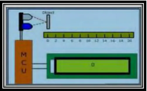
2.2 Position Sensor and Distance of Object Measured 5
2.3 Ultrasonic Sensor XL-Maxsonar EZ 23 6
2.4 XL-Maxsonar Beam Pattern 6
2.5 Arduino Pro Mini 7
2.6 System Architecture Non-Contact Height Measurement device 8
2.7 Assignment of PIC 16F877A 10
2.8 Configuration of Arduino Atmega pin 11
2.9 Infrared Sensor 15
2.10 Operation of Ultrasonic Sensor 16
3.1 Flow Chart of Project Methodology 20
3.2 PIC 16F877A Microchips 22
3.3 LCD display 1602 Blue 24
3.4 USB ICSP PIC Programmer 25
3.5 UIC – S Programmer 26
3.6 Jumper wire (male-female) 27
xi
4.1 Out of Range data 30
4.2 MikroC program by using MikroC PRO for PIC 30
4.3 LCD show the sign data is save 31
5.1 Experiment 1 and Experiment 2 of distance measured 33
5.2 Sequence of distance measured by manual measuring tool and ultrasonic sensor in Experiment 1 34
5.3 Sequence of distance measured by manual measuring tool and ultrasonic sensor in Experiment 2 36
5.4 Menu 37
xii
LIST OF ABBREVIATIONS, SYMBOLS AND
NOMENCLATURE
PIC - Peripheral Interface Controller
I/O - Input / Output
IC - Integrated Circuit
ROM - Read-Only Memory
LCD - Liquid Crystal Display
IR - Infrared
ADC - Analog to Digital Converter MCU - Microcontroller Unit
GPS - Global Positioning System
EEPROM - Electrically Erasable Programmable Read-Only Memory USB - Universal Serial Bus
PWM - Pulse-Width-Modulated
RC - Resistor-Capasitor
MB - Mega byte
CPU - Central Processing Unit
SD - Secure Digital
LED - Light Emitting Diode
xiii
SoC - System On Chip
GPU - Graphic Processing Unit
SDRAM - Synchronous Dynamic Random Access Memory OTP - One-Time Programmable
TTL - Transistor-Transistor Logic ICSP - In Circuit Serial Programming
1
CHAPTER 1
INTRODUCTION
1.0 Project Background
In this sophisticated era, many have to upgrade what they use, whether in technology, expertise, or equipment used. Distance measuring equipment are available, such as a tape measure may force someone to do the work over two or three times. With today's technology, it is a loss if a society is to continue to use old equipment. Development of distance measuring device equipped with storage systems using a microcontroller will assist and facilitate the work of measuring the distance as well as to store the data in the measure itself.
This project will use Peripheral Interface Controller (PIC) that can be
programmed to give instruction and to control that measurement device. PIC developed and marketed by Microchip Technology, is inexpensive microcontroller units that include a central processing unit and peripherals such as memory, timers, and input/output (I/O) functions on an integrated circuit (IC) (Lee et al. 2004). The PIC 16F877A is a microcontroller based on PIC16F87x. It has 256-byte of read-only memory (ROM). This microcontroller also has three input/output port which is suitable for the development of distance measurement device.
2 measurement. The used of this sensor for this project is to measure a distance of an object. 5 volt of battery will be used for this project to make it portable and easy to bring to anywhere. All the reading of distance measured will be display on the Liquid Crystal Display (LCD) which is a standard display device for hand-held embedded system. This LCD can display 16 characters in the two lines which is enough to display the distance’s reading until 5 significant figures and above. There are three push buttons on that device.
1.1 Problem Statement
Nowadays, measuring tool is important for the people especially for interior designer or general people. The problem they are facing today is that they must do multiple works just to measure and record that measured data. Besides, there is possibility that the paper which has the reading on it missing or misplace. In addition, there is always has an error to read the reading on that measuring tool because of the parallax error. This problem will make people do the same job two or three times. So, I can say this product will be helpful to solve the problem.
1.2 Objectives
a) To develop digital measuring tool that can measure distance and save data. b) To test the accuracy of measuring tools.
1.3 Work Scope
a) The data can be stored up to five (5) data of distance measured. b) The accuracy of measurement has one percent (0.1%) of error. c) The measuring range is cover from 5cm to 4m.
3
CHAPTER 2
LITERATURE REVIEW
2.0 Introduction
Literature review is the first step to understand the ideas to develop the measurement device using microcontroller with memory. This chapter will briefly detail about the previous idea and project about the distance measurement device and what component had been used in the previous project. In addition, this chapter will also describe about type of microcontroller and sensor that will be chosen in this project and the factor why it is been chosen.
2.1 Previous Project Work
This part will explain roughly about the previous project which is related to the actual project that will be developed. The project that chosen in this part are Smart Distance Measurement Systems Using IR sensor, General – Purpose Wireless Distance Sensor, and Development of Noncontact Height Measurement Device Fabricated Using Microcontroller HT46R232 as Foundation.
2.1.1 Smart Distance Measurement Systems Using IR Sensor
4 use the general IR sensor, a 16x2 LCD display to display the distance reading and power supply unit (Hubballi et al. 2015). While the software that they use is Kiel complier, embedded c, and multisim which used for simulation. Figure 2.1 shows the block diagram of distance measurement system.
Figure 2.1: Block Diagram of Distance Sensor
There are three main unit of working system which is a sensor unit, an analog to digital converter (ADC) which is inbuilt in PIC MCU and the LCD module (Meier 2014). The shorter the distance between sensor and the object, the bigger the intensity of IR radiation will be receive by the receiver and vice versa. The reflected ray that is received by receiver will send the signal to microcontroller and convert the analog signal to digital signal using the formula given below where Vpp value is refer to intensity of IR that is received by receiver.
Value = (Vpp) / (4.87*10^-3)
5 Figure 2.2: Position Sensor and Distance of Object Measured
Although the infrared sensor are much more cheaper but this sensor only fit for recognizing object within the scope of 10 to 15cm and it is also not accurate because it is easily sense radiations from the sun that will caused the correctable or non-correctable blunders at yield. In addition, signal misfortunes may happen at amplifier circuit if we use analogue IR sensor. However, the power utilization of IR sensor is lesser than ultra-sonic sensors and the transmitter and receiver of IR entirely basic.
2.1.2 General – Purpose Wireless Distance Sensors
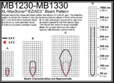
6 Figure 2.3: Ultrasonic Sensor XL-Maxsonar EZ 23
Figure 2.4: XL-MaxSonar Beam Pattern
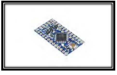
[image:23.595.153.536.300.579.2]7 furnished with an ATmega328 CPU running at 8 MHz, can be powered at any voltage between 3.3 V and 12 V and it size just 18x33 millimeter.
Figure 2.5: Arduino Pro Mini
2.1.3 Development of Noncontact Height Measurement Device Fabricated Using Microcontroller HT46R232 as Foundation
This journal basically present about a device that can measure level, distance, and height specifically for employed in construction works (Shieh et al. 2013). The framework created in this study combines laser modules, ultrasonic sensor, inertial sensors and a HT46R232 microcontroller. Tangent theorem of trigonometric functions is also added by the system to the microcomputer controller for height computation. The improvements that have been added into the project are the uses of inertial accelerometer applications. One of the uses of accelerometer is when equipment cannot acquire a global positioning system (GPS) signal, it can be utilized to sense moving data and give signals to navigation equipment to complement the GPS signal errors.