2,850+
OPEN ACCESS BOOKS
98,000+
INTERNATIONAL
AUTHORS AND EDITORS
91+ MILLION
DOWNLOADSBOOKS
DELIVERED TO 151 COUNTRIES
AUTHORS AMONG
TOP 1%
MOST CITED SCIENTIST
12.2%
AUTHORS AND EDITORS FROM TOP 500 UNIVERSITIES
Selection of our books indexed in the Book Citation Index in Web of Science™ Core Collection (BKCI)
Chapter from the book Advances in Microfluidics - New Applications in Biology, Energy, and Materials Sciences
Downloaded from: http://www.intechopen.com/books/advances-in-microfluidics-new-applications-in-biology-energy-and-materials-sciences
World's largest Science,
Technology & Medicine
Open Access book publisher
Interested in publishing with InTechOpen?
Microfluidics for Ultrafast Spectroscopy
Adrien A. P. Chauvet
Additional information is available at the end of the chapter
http://dx.doi.org/10.5772/64428
Abstract
Ultrafast laser technologies became one of the essential tool in the characterization of mo‐ lecular compounds. Being comprised of spectroscopists, laser scientists, chemists and bi‐ ologists, the “ultrafast community” is often disconnected and consequently unaware of the developments in microfluidic systems. The challenges of studying limited amount of precious liquid sample by means of ultrafast spectroscopy remains silent and, while no commercial systems are available, each research group is developing its own “home-made” options. This chapter will therefore contribute in filling up the gap that exist be‐ tween the two communities, that of the ultrafast spectroscopy and that of microfluidics by revealing the importance of this analytical tool as well as the advantages of applying microfluidic technics to it. In this goal, the chapter will focus of the recently developed microfluidic flow-cell. With a minimal volume of about 250 µL, the flow-cell enables the study of precious protein complexes that are simply not available in larger quantities. The multiple advantages of the microfluidic flow-cell will be illustrated by the analysis of the cytochrome bc1. In particular, the study will describe how the capabilities of the mi‐
crofluidic flow-cell enabled the resolution of the ultrafast electronic and nuclear dynam‐ ics of specific embedded chromophores.
Keywords: Microfluidics, Ultrafast Spectroscopy, Liquid Sample
1. Introduction
The aim of this chapter is to address the gap that exists between two research communities: ultrafast spectroscopy and microfluidics. Indeed, the development of pulsed laser systems in the last few decades has ushered in new techniques in ultrafast spectroscopy. These techniques have opened new doors for the study of fundamental photo-chemical and photo-physical behavior of a variety of photosynthetic protein complexes.[1] For methodological reasons, i.e. samples being rare and the use of highly specialized equipment, there existed a pressing need to apply microfluidics systems in ultrafast spectroscopy, two fields that unfortunately
developed separately and whose researchers are rarely knowledgeable in both areas. For the microfluidic readers who may be unfamiliar with this literature, I introduce, in the first part of this chapter, the basic concepts of ultrafast pump-probe spectroscopy. In so doing, I highlight the relevance of this technique in gaining understanding protein dynamics and therefore biological properties and functions. It is in fact due to the laborious procedures that are involved in the purification processes of these proteins complexes that most biological samples are only available in sub-milliliters quantities. In the second part of this chapter, I will therefore expose some of the most common solutions that are in use in order to manipulate liquid samples in ultrafast spectroscopy. Finally, in the third part of this chapter, I describe one of the latest applications to the field of ultrafast spectroscopy—what is now called microfluidics—as it handles micro-liters volumes of a given sample. I illustrate the benefits of the application of such a microfluidic system through an analysis the of the cytochrome bc1. I conclude with a discussion on the areas of the present microfluidic flow-cell in need of further research and investigation.
2. The need for microfluidics in ultrafast spectroscopy
In this section I will introduce the field of ultrafast spectroscopy to which the microfluidics systems will be applied. I describe the basics of the technique and its relevance to the current fundamental research efforts in biochemistry and biophysics. In the last section of this chapter, I cover the practical challenges that emerge from such studies, which justify the need for microfluidics.
2.1. Ultrafast transient absorption spectroscopy
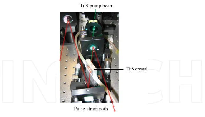
Transient absorption is a spectroscopic technique whose aim is to resolve the relaxation dynamics of an excited molecule “simply” by looking at its spectral modifications. The technique involves two principal light beam: a pump and a probe. While the role of the pump is to promote the molecule to a particular excited state, the probe is used to “look” at the state in which this molecule is in. The fact that these light beams are not continuous but are strains of pulses allows one to excite the molecule for a brief instant (the duration of the pulse) and to probe its state at a later time. The light pulses are first produced in a cavity (oscillator) that is built around a doped crystal such as titanium doped sapphire crystals (Ti:S) as shown in Figure 1.[2]
milli-Joules per pulses. It is these amplified pulses that are then split into pump and probe pulses.
Figure 2. Pump-probe experimental scheme.
[image:4.482.63.416.351.483.2]more, the high repetition rate and the development in matters of laser stability and detection system gives the ability to monitor the absorption changes of a single molecule out of a thousand (corresponding to changes of ~10-4 OD) in less than a second of accumulation time. [4] With such setups, it is for example possible to trigger the charge separation in the Photo‐ system I protein complex and to follow the liberated electron as it progresses from one side of the protein to the other.[4] Another example is the monitoring of the heme-ligand dissociation and rebinding dynamics that results from the absorption of a photon such as it is the case of various types of cytochromes.[5, 6]
The use of non-linear optics, such as in the famous and various kind of optical parametric amplifiers (OPA, Non-collinear OPA and multi-pass OPA)[7] as well as the different pulse shaping devices (in either transmission or reflection),[8] gives the ability to tune both the pump and the probe to the desire wavelength, therefore enabling to excite and to follow a particular molecular transition. For example, in the study of the bacterial reaction centers complexes, being comprise of multiple types of pigments that are spectrally distinct, careful tuning of the pump allows to preferably excite one pigment while living the others in their fundamental state.[9]
It is therefore out of the development in laser technology and specifically in tunable table-top pulsed lasers that the field of ultrafast spectroscopy came to know the success it knows today.
2.2. Studying biological samples
2.3. The challenges of the application
As discussed above, ultrafast transient spectroscopy is suitable for the study of biological samples. These samples are usually made of purified and solvated proteins. Once a particular molecule is excited, the deposited energy ultimately dissipates into the solvent (so long as the changes are not permanent). It is to remember that the typical repetition rate of the pulses are in the order of the kHz and at this rate the sample is excited about every milliseconds. The risk is that the photo-induced molecular modifications live for a time that is comparable, which will then results in a rapid saturation of the sample. In other words, the excited molecule might not have sufficient time to relax to its fundamental state before the coming of the next light pulse. Saturation thus takes place and as the molecules gets overexcited: they are unable to release the deposited energy quickly enough and end up by “burning”. In order to avoid such consequences, the sample is usually flown in front of the laser beams. The condition is that the flux is high enough so that the sample is refreshed for each laser pulse.
The second major constraint is related to the quantity of the sample available. The sample being made of purified proteins, it is then concentrated in order to reach an optical density that is suitable for spectroscopic analysis. Ideally, transient absorption spectroscopy requires an optical density of about 0.6 for the transition of interest, which in the case of heme protein corresponds to a concentration of hundreds of micro molars. The samples are consequently limited in terms of volumes and sub-milliliters quantities already requires months-long of successive growth of the organisms and protein purification cycles.[11, 12]
The third constraint concerns the susceptibility of the sample in respect to its solvent and atmosphere in which it is enclosed. Indeed some biological samples are hydrophobic and require to be dissolved in various chemicals in order to avoid aggregation and the subsequent scattering of the light pulses, such as it is the case for solvated porphyrins. Many samples are also sensitive to oxygen and therefore require the atmosphere to be controlled. For example, myoglobin is able to effectively bind a variety of diatomic molecule. It however has a high affinity for oxygen, so much that it is not possible to study its deoxygenated state unless in anaerobic conditions.[13]
3. Most common solutions available
In this section I will review different techniques that are commonly employed to flow the sample in front of the laser beam. I will discuss the advantages and inconveniences of each in terms of their compatibilities with the requirements of ultrafast spectroscopic laser systems.
3.1. Flow cell
[image:7.482.194.289.283.374.2]The main idea is to flow the sample in between two transparent plates. These windows are usually made of quartz so as to permit the broadband (near UV-Visible-near IR) beams to pass through. This type of cell allows for small path lengths and thin windows, down to 0.02 mm such as the one shown in Figure 3, therefore reducing scattering of the excitation beam through the quartz. The thin windows also have the advantage to minimally alter the pulse duration (limited group velocity dispersion), therefore allowing for an optimal time resolution. Furthermore, the cell is steady and its stability allows for optimal signal to noise levels.
Figure 3. Flow cell from Starna Cell [14]
The quartz cells, by themselves, are commercially available.[14] However, due to their size, these cells already enclose about one milliliter of sample. Furthermore they must be connected to a pump, typically a peristaltic or flow-through pump, in order to generate the flow. Altogether, the flow cell system requires few tenth of milliliters and is consequently not adequate for precious samples that are simply not available in such quantities.
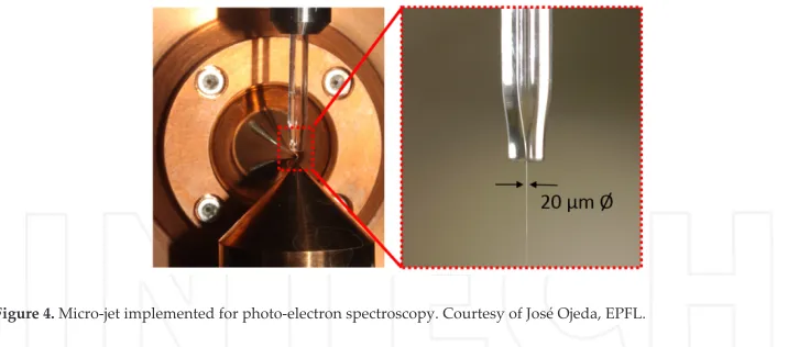
3.2. Liquid micro-jet
Figure 4. Micro-jet implemented for photo-electron spectroscopy. Courtesy of José Ojeda, EPFL.
The inconvenience of having to produce a constant flow rate is that the sample must pass through a sophisticated HPLC pump,[15-17] which consequently requires sample volumes that are larger than our targeted sub-milliliter. Note also that while passing in either the air or in vacuum, the sample’s solvent is subjected to evaporation. In such conditions, recycling of the sample results in a change of the sample’s concentration and temperature over the course of the experiment.[16] Furthermore, the high speed at which the sample go through the nozzle induces charging of the liquid and or of the nozzle, which might alter the measurement.[17]
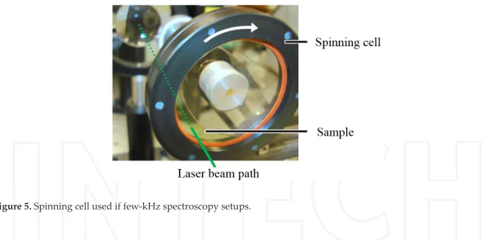
3.3. Spinning /moving cell
The idea behind the spinning-cell is similar to that of the flow cell as the sample is housed between two circular glass plates that are spaced by the desirable optical path-length.[18] While rotating, the sample either creates a rim at the edge of the cell, or at lower speed, the solution remains at the bottom of the cell and is constantly mixed due to friction with the glass as shown in Figure 5. The advantage is that it typically requires minimal amounts of sample (~0.3 mL) as well as to provide control over the initial atmosphere in which the sample in enclosed since the sample is hermetically confined.
However, because the rotation of the glass plate causes the excitation beam to sweep a large surface, the cleanness of the plates is directly related to the noise. It is consequently burden‐ some to clean. Furthermore, the fact of having a moving piece of glass in which the beam is focused renders the alignment of the cell crucial, and any slight asymmetry of the glass plates has consequences on the transmitted probe beam. Also, since the glass plates are typically few cm in diameter, the required minimal thickness of the glass lowers the time resolution. Another inconvenience is that once the cell is set it does not allow access to the enclosed sample and each experiments therefore requires its own sample preparation.
apparatus. Through these few examples I hope to have convinced the reader of the need for a development in the application of microfluidic system to the field of ultrafast spectroscopy.
4. Recent improvement and application: the microfluidic flow cell
In this section I will describe the recently developed microfluidic flow-cell in order to illustrate the importance and advantages of applying microfluidic systems to the field of ultrafast spectroscopy. I will show that recent improvements in the field of microfluidics have the capabilities to solve the previously mentioned constraint all at once. I will thus discuss the advantages of the system in light of the other technics. Following the technical properties I will illustrate the flow-cell’s effectiveness through a study done on rare bc-cytochrome and conclude with an appeal for further development.
4.1. The microfluidic flow-cell
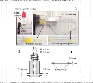
The microfluidic flow-cell, [19] as illustrated in Figure 6, is composed of three main elements that are connected via flexible tubing of 1-mm diameter:
The decantation chamber is a home-made polymer cylindrical chamber as shown in Figure 6.
[image:9.482.62.416.70.244.2]The 0.5-mm diameter inlet and outlet are at the bottom of the chamber in order to minimize turbulences that are created at high flow rates. The chamber requires a minimal amount of ~50 µL of liquid sample in order to have a continuous flow between the inlet and outlet. Any excess of sample fills up the chamber and allows the bubbles that might be enclosed in the closed circuit to rise to the surface. The bubbles are naturally trapped by the chamber while passing through at low flow-speed. At high flow-speed however, larger sample volume are required in order to avoid the suction of air due to the liquid’s turbulences. The top of the chamber is threaded to fit a standard septum screw cap. This allows for the addition of chemicals to the enclosed solution while keeping the confined atmosphere protected and avoiding evaporation of the solvents.
The capillary window is made of a square quartz silica capillary bought from Composite Metal
Services Ltd (CMS). It has a path-length of 0.5 mm with 0.1-mm thin walls. Knowing that the focus of the laser beam is about 100 um in diameter, the window can easily be set within the beam path. The capillary is fixed at the center of a xyz-rotation mount that allows for fine adjustment of the angle between the incident beam and the window.
The turbisc pump is a design from CSEM.[20] In short, the flow is created by direct friction
between a grooved barrel and the liquid. The inner volume that the pump contains is about 100 µL only. Because the housing and the seal are respectively made out of Polyetherimide and of Polyetheretherketone, the pump is relatively resistant to chemicals.
Figure 6. (A) Overall view of the assembled system, with zoom on the capillary junctions. (B) Side view of the bubble
chamber and (C) of the capillary window. Reproduced from Ref. [19].
[image:10.482.66.420.181.499.2]Figure 7. Measured flow-rate (dots) and its best fit (line, 2nd order polynomial) while the pump is connected to ~6 cm of
1-mm diameter tubing and ~1-cm long 0.5x0.5 mm2 square capillary. In order to ensure fresh sample at each laser shot,
while assuming a typical laser focus size of 100 µm, the expected maximum repetition rate of excitation is indicated as a reference only (right axis).
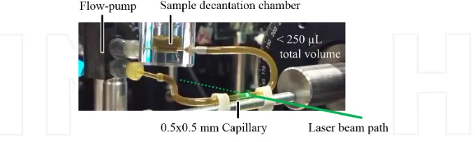
While assuming a typical laser focus diameter of 100 µm within the 0.5x0.5 mm2 square capillary, the flow, when assumed to be uniform, is expected to effectively refresh the sample within the laser focus for each laser shot at an excitation rate of up to ~14 kHz. In practice, it is to remember that the flow is impeded on the edges of the capillary and consequently the value of 14 kHz has to be taken as an upper limit only. Taking into account that the inner volume of the pump is only about 100 µL, it represents one of the best (if not the actual best) compromise between flow-rate and required volume. The assembled microfluidic flow cell, in working conditions is shown in Figure 8.
Figure 8. Microfluidic flow-cell in action
4.2. Example of application: the study of cythochrome bc1 complexes
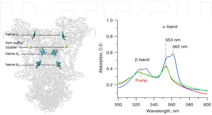
[image:11.482.74.414.412.514.2]cyt bc1 complex is a key player in mitochondrial and bacterial respiratory chains.[21] It is the main actor in the protonmotive Q cycle and results in the formation of a proton gradient across the membrane via a series of embedded hemes as shown in Figure 9.[22-24] The generated potential gradient serves as the driving force for the synthesis of ATP, the universal energy transporter in living organisms. The understanding of the protein complex is therefore of primary importance. However the sample is rare and mainly because of the limited quantity available after each purification process, the heme dynamics were until then never studied by means of ultrafast spectroscopy.
Figure 9. (Left) Structure of the bc1 complex[25] with the protein backbone being shaded for clear visualization of the
key actors in the proton-coupled-electron mechanisms. (Right) Static absorption spectrum of the sequential reduction and oxidation of the cyt bc1 dimer complex: after pre-reduction by ubiquinol and before (red, c1-hemes reduced) and
right after (blue, b- and c1-hemes reduced) the addition of dithionite, and at the end, after oxidation of the complexes
by oxygen (green, c1-hemes reduced). The 523-nm excitation pump is indicated as reference. Reproduced from Ref. [6]
with permission from the Royal Society of Chemistry.
[image:12.482.71.412.170.355.2]Figure 11. Photo-dissociation of the c1-heme (left) and photo-oxidation of the b-heme (right) upon light excitation of
the cyt bc1 complex. Reproduced from Ref. [6] with permission from the Royal Society of Chemistry.
Figure 10. (A) Spectra at selected time delays while both b- and c1-hemes are reduced. (B) Spectra at selected time de‐
lays while only the c1-hemes are left reduced. (C) Difference (A-B) corresponding solely to the signal of the ferrous
[image:13.482.68.415.331.556.2]The b-heme’s high electronic reactivity makes sense in the light of cyt bc1 having to efficiently fulfil its role in the Q-cycle: it favours the reduction and oxidization of the ubiquinone and ubiquinol, respectively.[22] The b-hemes have to efficiently “process” the electrons, which demand them to easily loose or gain electron. Similar electronic-reactivity would in fact be counterproductive in soluble cytochromes as they would less efficiently keep their electrons from being scavenged by other solutes. The hydrophilic environment of the bc1 core on the other hand preserves the b-hemes from unwanted solvated electron carrier and their high electronic reactivity is then an advantage. In contrast to the high electronic reactivity of the b-hemes, the high photo-dissociation quantum yield of the c1-hemes can be understood as being an efficient “heat sink” that protects the reduced state of the heme against light excitations. Overall, this study illustrate that, even though the b-hemes in cyt bc1 and in other cyt b have similar ligation to their protein backbone; specific structural constraints and amino-acid arrangements result in clearly different responses, and therefore functions. While cytochromes were known to serve only as electron carriers, this study demonstrates that with the appro‐ priate environment, light-induced charge separation can readily be initiated within single heme structures. The use of the microfluidic flow-cell therefore not only enabled the study of this rare protein complex, but allowed to shine light on the relevance of local heme-bonding and structural environment in initiating larger chemical reactions. This particular case study is only one example of how the field of ultrafast spectroscopy can benefit from the application of microfluidics technologies.
4.3. Call for development
As I mentioned, the described microfluidic flow-cell, beside the numerous advantages it provides in respect to the other systems commonly employed, is certainly not perfect, which leaves room for improvement.
For example, in terms of sample volumes, most of the liquid is contained in the pump that is used to generate the flow and in the tubing. Miniaturization of both would allow to use even smaller sample volumes. Already the small turbisc pump that is employed uses a newly developed friction based technologies[20] that is able to flow even viscous samples. The samples studied in ultrafast spectroscopy are however water-like and, not being in need of the actual viscous sample capabilities of the pump. I can therefore imagine that a simplified version of the pump would be sufficient and require even smaller volumes. Concerning the actual 1 mm diameter tubing, that links the pump with the capillary, it could be replaced by other microfluidics technologies that uses micro-channels that are specifically designed for spectro‐ scopy.[26] The goal through these proposed improvements is to reduce the amount of liquid used, keeping in mind that reducing further the diameter of the channels might impede the overall flow rate.
issue, I can imagine that the shaft would be replaced, not by another mechanical interaction, but remote electromagnetical interaction so as to preserve the inner atmosphere of the sample. Such systems are already implemented for applications in biomedical for example.[27] Furthermore, the microfluidic flow-cell uses epoxy beads in order to hermetically fit the square capillary in the cylindrical tubing. Better seal could be achieved if the capillary themselves were to be made with initial beads on each sides such as it is the case for the larger commercially available flow-cells.[14]
At last, I would like to precise that, due to friction between the sample and the capillary, the capillary does not provide with a flow that is homogeneous. Sample that is the closest to the window has consequently lower flow rate and might not be refreshed for each laser pulse, being therefore subjected to photo-damage. One solution would be to employ the newly developed Electro-Osmotic flow systems that are used to generate homogeneous flows.[28] In conclusion, the microfluidic flow-cell that I propose is specifically designed to fits the requirement imposed by the ultrafast spectroscopy of quantity-limited and sensitive sample, while it remains cost effective and easy to use. As an illustration of the flow-cell’s effectiveness, I showed how its implementation enabled the study of the cytochrome bc1. More precisely, I was able to resolve the ultrafast electronic and nuclear motions that precedes some of the larger physiological function of the protein. The microfluidic flow-cell not only facilitates but also opens the door to the study of a whole range of samples that cannot be purified in large quantities such as it is the case for most organic compound that are extracted from living organisms.
The advantages of this microfluidic flow-cell over other pre-existing solutions are clear; as clear as there is room for development.
5. General conclusion
monitoring chemical changes in “real time”, the microfluidic system enables studies that were otherwise not possible. The advantages of microfluidics over other usual systems are numer‐ ous but as it represents only one of the first attempt, there is ample room for improvement. In this regard, one of the goal of this chapter is to serve as an initial step in an effort to bridge the microfluidics community with that of ultrafast spectroscopy in order to foster new ideas, new applications and new perspectives.
Acknowledgements
Thanks to Professor S. Savikhin (Purdue University, USA) as well as to Professor M. Chergui (EPFL, Switzerland) from whose laboratory of Ultrafast Spectroscopy the different pictures are taken. The described microfluidic flow cell as well as the cyt bc1’s study have been funded by the Swiss NSF via the NCCR:MUST, by the FP7 Marie Curie COFUND, by the Excellence Initiative of the German Federal and State Governments (EXC 294, BIOSS) and by the Deutsche Forschungsgemeinschaft (RTG 1976).
Author details
Adrien A. P. Chauvet*
Address all correspondence to: [email protected]
GAP-Biophotonics, Geneva University, Geneva, Switzerland
References
[1] Berera R, van Grondelle R, Kennis JTM. Ultrafast transient absorption spectroscopy: principles and application to photosynthetic systems. Photosynth Res. 2009;101:105-18. [2] Koechner W. Solid-State Laser Engineering. 6th ed: Springer; 2006.
[3] Rosspeintner A, Lang B, Vauthey E. Ultrafast Photochemistry in Liquids. Annu Rev Phys Chem. 2013;64:247-71.
[4] Chauvet A, Dashdorj N, Golbeck JH, Johnson TW, Savikhin S. Spectral Resolution of the Primary Electron Acceptor A0 in Photosystem I. J Phys Chem B. 2012;116(10):3380-6. [5] Vos MH, Battistoni A, Lechauve C, Marden MC, Kiger L, Desbois A, et al. Ultrafast
[6] Chauvet AAP, Al Haddad A, Kao W-C, van Mourik F, Hunte C, Chergui M. Photo-induced dynamics of the heme centers in cytochrome bc1. Phys Chem Chem Phys. 2014.
[7] Cerullo G, De Silvestri S. Ultrafast Optical Parametric Amplifiers. Rev Sci Instrum. 2003;74(1).
[8] Weiner AM. Femtosecond Pulse Shaping Using Spatial Light Modulators. Rev Sci Instrum. 2000;71(1929).
[9] Chauvet A, Sarrou J, Lin S, Romberger SP, Golbeck JH, Savikhin S, et al. Temporal and Spectral Characterization of the Photosynthetic Reaction Center from Heliobacte‐
rium modesticaldum. Photosynth Res. 2013;116:1-9.
[10] Rosspeintner A, Bernhard Lang B, Vauthey E. Ultrafast Photochemistry in Liquids. Annu Rev Phys Chem. 2013;64:247-71.
[11] Mitra S. Sample Preparation Techniques in Analytical Chemistry. Winefordner JD, editor: John Wiley & sons, INC.; 2003.
[12] Berg JM, Tymoczko JL, Stryer L. The Purification of Proteins is an Essential First Step in Understanding their Function. In: Moran S, Hadler GL, Zimmerman P, editors. Bi‐ ochemistry. 5th edition ed: W H Freeman; 2002.
[13] Monni R, Al Haddad A, van Mourik F, Auböck G, Chergui M. Tryptophan-to-Heme Electron Transfer in Ferrous Myoglobins. PNAS. 2015;112(18):5602-06.
[14] Starna Cells. Linear Flow Cells, Type 48 series http://www.starnacells.com/d_cells_s/ flow/linear/T048.html2015.
[15] Arrell CA, Ojeda J, Sabbar M, Okell WA, Witting T, Siegel T, et al. A Simple Electron Time-of-Flight Spectrometer for Ultrafast Vacuum Ultraviolet Photoelectron Spectro‐ scopy of Liquid Solutions. Rev Sci Instrum. 2014;85(103117).
[16] A. K. Charge Transfer to Solvent Dynamics in Iodide Aqueous Solution Studied at Ionization Threshold: Freie Universität Berlin; 2015.
[17] Duffin AM, Saykally RJ. Electrokinetic Power Generation from Liquid Water Micro‐ jets. J Phys Chem. 2008;112:17018-22.
[18] Savikhin S, Wells T, Song P-S, Struve WS. Ultrafast Pump-Probe Spectroscopy of Na‐ tive Etiolated Oat Phytochrome. Biochemistry. 1993;32:7512-8.
[19] Chauvet A, Tibiletti T, Caffarri S, Chergui M. A microfluidic flow-cell for the study of the ultrafast dynamics of biological systems. Rev Sci Instrum. 2014;85: 103118. [20] Lisibach A, Casartelli E, Schmid N, editors. Flow Investigation in a Disk Micropump.
[21] Berry EA, Guergova-Kuras M, Huang L, Crofts AR. Sructure and Function of Cyto‐ chrome bc Complexes. Annu Rev Biochem. 2000;69:1005-75.
[22] Crofts AR. Proton-coupled electron transfer at the Qo-site of the bc1 complex con‐ trols the rate of ubihydroquinone oxidation. Biochem Biophys Acta. 2004;1655:77-92. [23] Hunte C, Solmaz SRN, Palsdóttir H, Wenz T. A Structural Perspective onMechanism
and Function of the Cytochrome bc1 Complex. Results Probl Cell Differ. 2007;45:253-78.
[24] Trumpower BL. Cytochrome bc1 Complexes of Microorganisms. Microbiol Rev. 1990;54(2):101-29.
[25] Solmaz SRN, Hunte C. Structure of Complex III with Bound Cytochrome c in Re‐ duced State and Definition of a Minimal Core Interface for Electron Transfer. J Biol Chem. 2008;283(25):17542-49.
[26] Horrocks HM, Tosatto L, Dear AJ, Garcia GA, Iljina M, Cremades N, et al. Fast Flow Microfluidics and Single-Molecule Fluorescence for the Rapid Characterization of α-Synuclein Oligomers. Anal Chem. 2015;87(17):8818-26.
[27] Al-Halhouli AT, Kilani MI, Büttgenbach S. Development of a novel electromagnetic pump for biomedical applications. Sensor Actuat A-Phys. 2010;162:172-6.
![Figure 3. Flow cell from Starna Cell [14]](https://thumb-us.123doks.com/thumbv2/123dok_us/7821865.173620/7.482.194.289.283.374/figure-flow-cell-from-starna-cell.webp)