International Journal of Innovative Technology and Exploring Engineering (IJITEE) ISSN: 2278-3075,Volume-8 Issue-6, April 2019
Abstract: Modern day power system statistics and dynamics
include the management and supplementing of reactive power in accordance with load requirements and specific considerations. The losses are significantly increased and reduces the ability of power delivery to the load end is attributed to the poor reactive power management. The FACTS technology is the latest revolution in the field of transmission systems which improve the worth and steadfast of power arrange to the load end. Among the various FACTS devices, Distributed Power flow controller is discussed in this paper and the suitable control schemes for the power flow controller are analyzed and the appropriate one is proposed. The various control techniques are traditional proportional integral method, sliding mode converter, fuzzy based control and artificial neural network assisted control strategy. The performance measure is harmonic analysis of the
source current and voltage across the load.
MATLAB/SIMULINK is the software platform used to defend the advantages of the superior control technique compared to others.
Index Terms: power flow, transmission system, flexible AC
transmission, Distributed power flow controller, proportional integral control.
I.INTRODUCTION
Power flow is limited by control of active power in the present day power system scenario using different controlling techniques and devices called power flow controlling devices. Flexible AC transmission system is a revolution in the area of transfer of power transmission system. Distributed Power - flow controller (DP FC) is a novel variant of Unified Power - flow controller (UP FC) and a class of FACTS device which control various parameters like voltage of the buses, impedance of the power line, phaseangle adjustment between starting and finishing end voltages. The operation of the shunt converter does not relate or depend on the operation or working of series converter due to the absence of dc link in case of DPFC. The design of series converter is based on distributed concept of modeling of FACTS controllers. The reliability of the transmission system and minimization of the overall cost is achieved by the usage of individual single phase converters in contrast to the traditional three phase converter. The DPFC configuration is based on the transmission line enabled exchange of active power in the system which predominantly
Revised Manuscript Received on April 07, 2019.
D Narasimha Rao, Department of EEE, Koneru Lakshmaiah Education
Foundation, Vaddeswaram, A.P, India.
P Srinivasa Varma, Department of EEE, Koneru Lakshmaiah Education
Foundation, Vaddeswaram, A.P, India.
occurs in at 3rd harmonic frequency order. Single phase to ground voltage applied to the converter of the DPFC, eliminates the need for isolation of high voltage components. Therefore, the reduced cost of economics is an added advantage for DPFC unlike UPFC. “The expanding use of power causes more request in utilizing the sustainable power provenance make it mandatory to control a colossal power that empowers the power framework for a fast link between the sustainable power sources and the remain by control age. This requests the accessibility of remain by control at whatever point sustainable power source can't supply the heap [1].Therefore the need to control the power techniques is expanded. The specification used to control voltage esteem, transmission edge, line impedance is balanced with a specific end goal to improve the power stream [2, 3]. The Power Flow Controlling Device (PF-CD) is a gadget that tries to change framework specification to upgrade the power stream execution. The joined FACTS parts are the proper gadgets to upgrade dynamic power stream. [4, 5] .The UPFC is the capable PF-CD, ready to alter line inside edge of the machine, transport voltage, and the specification of power line framework. The real task of the UPFC is executed with arrangement converter by infusing the voltage, to control stage point, extent, of the power line [6]”. DPFC copies UPFC in freely modifying the line impedance, control ability, inner point between the transport voltage and instigated EMF [7]. In DPFC there is nonattendance of DC connect which makes to interface converters consecutive in UPFC.
AC A
B C
A B C
a b c
a b c
A B
C CB AC
A
HIGH PASS FILTER AC/DC AC/DC AC/DC AC/DC
SHUNT CONVERTER
SERIES CONVERTERS
THREE-PHASE SOURCE
TRANSFORMER TRANSFORMERTHREE-PHASE SOURCE 1
TRANSMISSION LINE
B1 B2 B3 B4
COUPLING TRANSFORMER
1 2
Fig.1. Complete Line Diagram of DPFC System The electrical representation of the DPFC circuit arrangement is presented in Figure1. The presence of an separate capacitor to each single phase series converter is a remarkable feature in case of DPFC. Another significant variation that is exclusively found in DPFC is that the incorporation of filter,
Enhancing the Performance of DPFC with
Different Control Techniques
Enhancing the Performance of DPFC with Different Control Techniques
typical high pass filter, which an extra element added to the line if it encounters a star delta transformer configuration.
The reasons for choosing DPFC over UPFC is attributed to the following points
i. Minimization of the cost due to reduced rating of series converter and absence of the need for large voltage isolation.
ii.The steadyfast of the overall circuit configuration is enhanced due to the choice and arrangement of series converter.
II. DPFCPRINCIPLE
The exchange of the regulation of the active power is enabled through the transmission line existing between AC terminals of the series and shunt converters. Fourier analysis is an robust computational tool for the microscopic harmonic analysis of the voltage and current waveforms [7].
The active power of the transmission system is given by
(1)
i = frequency of the harmonics and denoted by order V= Voltage across the line to ground
I= current flowing through the line
= phase difference between the harmonic voltage and current
“From the expression, it is noticed that at dissimilar frequencies, the real power is isolated from each other and the active power at any frequency is not altered by the magnitude or phase angle of the current and voltage. The frequency component doesnot show any variation on the active power. Therefore, the active power can be generated and transferred as well as consumed at different frequencies”. There is no frequency constraint on the flow of the active power.
In case of DPFC, the parallel converter takes the reactive power from the gird at the base frequency i.e., system nominal frequency. This reactive power is inserted into the gird at an frequency other than elementary frequency whenever required [7-8]. The current corresponding the non elementary frequency will pass through the high power line system. The series converter of the DPFC generates the useful power on the basis of the requirement for active power at the nominal frequency. The effective power consumed and generated the base frequency and off nominal frequencies respectively are said to be equal and same.
“The off nominal frequencies are allowed through the high pass filter which facilitate return path for the harmonic components. The path provided by the series converter of DPFC, shunt converter of DPFC in combination with the ground. Among the harmonics present in the system, 3rd harmonic is dominating and has special attention compared to the other harmonics. Therefore, the third harmonic is chosen for the facilitation of active power exchange the undesirable zero sequence component present in the system which can be subsided by the appropriate transformer connection namely star delta configuration. This transformer scheme for arrangement of winding is predominantly used in
the maximum times during the operation of power system for variation in the voltage level. Therefore, this configuration for mitigation of zero sequence components eliminates the need for any other filtering arrangements” [8, 9].
2.1. Control principle of DPFC
The control of the novel FACTS device, DPFC involves control of the two DPFC converters and a coordinated control scheme for the two converter controls. The entire control scheme is depicted in Figure 2. The converter control scheme is employed at the respective terminals of the converter and is called local controllers. The centralized control coordinates the individual converter controllers in addition to the control of various parameters of DPFC.
AC A
B C
A B C
a b c
a b c
A B
C CB AC
A
HIGH PASS FILTER
SERIES CONTROL CENTRAL
CONTROL AC/DC AC/DC AC/DC AC/DC
SHUNT CONTROL
SHUNT CONVERTER SERIES CONVERTERS
THREE-PHASE SOURCE
TRANSFORMER TRANSFORMERTHREE-PHASE SOURCE 1
TRANSMISSION LINE
B1 B2 B3 B4
COUPLING TRANSFORMER
1 2
SERIES CONTROL
SERIES CONTROL
Ish ref Vse ref
Fig.2. Line Diagram of DP-FC with Controller
2.1.1. Main Control
At the framework level, the focal control is subject to the useful task of the DP-FC; they are sodden out power motions at low recurrence, control stream control and awry segments adjusting. The preeminent capacity of the principle control regularly known as focal controller is to produce reference signals for supervised converters of the DP-FC. These are produced at the framework recurrence. [8] The focal control gives mentioned value of current and voltages for both the controllers as per the framework necessity.
2.1.2. Series Control
Arrangement seris control is available in all the single stage supervising circuits. The controller is to settle the capacitor voltage of converter will help of third symphonious voltage or streams. [7] It infuses voltage at supply recurrence affirmed by the fundamental control. In DP-FC arrangement converter control, the real control circle is the third consonant recurrence control. For DC voltage control phasor control standard is connected [9].
2.1.3. Shunt Control
It infuses a settled power which blend of key and third symphonious segment current into transmission line keeping in mind the end goal to transmit the genuine power for arrangement converters is the principle target of shunt control. At the key recurrence of the third consonant current and transport voltage are bolted. The adage of parallel converter is to trade required Q VAR'S to framework and furthermore keeping up settled DC capacitor voltage [7, 8, 9].
International Journal of Innovative Technology and Exploring Engineering (IJITEE) ISSN: 2278-3075,Volume-8 Issue-6, April 2019
3.1. Controller pattern using PI
The transfer function of the PI controller is described as:
( )= + (2)
Corresponding increase is inferred utilizing KP = 2.ξ.ωn.C which ascertains the execution of the DC interface voltage control. So also, the vital pick up is inferred utilizing KI =Cωn2 that decides its settling time.[10] The PI controller is to set the DC-interface voltage as adequacy of the d hub current of the APF inverter to control the DC-connect voltage for covering the inverter misfortunes in view of its reference esteem. The distinction of reference estimation of the APF present and estimated esteem estimated load or stack current.
3.2. Sliding Mode controller (SMC) of DC voltage SMC strategy has been normally applied for power converters problems, because of its operation characteristics like stability, response quick and strength throughout high variation in load [11, 12]. The management action SMC utilizes SM theory as a jump perform that is given by the equation (3).
s(y) =k.sign(y) (3)
“The Lyapunov perform should be dropped at zero; and to attain this, it's decent that its spinoff isn't positive [11]. To minimize the chattering development thanks to the discontinuous nature of the controller, it is important to outline a unique function in neighborhood of the slippy surface with most and minimum limit value. If a degree of the state mechanical phenomenon falls at intervals this interval, a swish function will replace the discontinuous a part of the control. Thus, the controller becomes”
= { / .(y) | (y)| < ≠ 0
.( (y)) | (y)| > (4) Where, kc represents the optimal finest value. In order to
control the DC link voltage Vdc and to remove the chattering
by using this SMControl, the block diagram of the SMC strategy is given by Fig. 3. As per Fig.3, the sliding surface ds(y)/dy = 0 is used to synthesis a command current I*. In this
case I* is given by
I*= . ( ) (5)
V*dc
Vdc +
-I* Kc
[image:3.595.324.536.266.840.2]
Fig.3. line diagram of SM Controller for voltage setup
3.3. Introduction and Design of proposed methodology Fuzzy Logic Controller
There are two noteworthy parts of fuzzy rationale controller they are Takagi– Sugeno and Mamdani compose, in light of fluffy tenets segments were arranged this paper is centers around mamdani type fuzzy controller with a specific
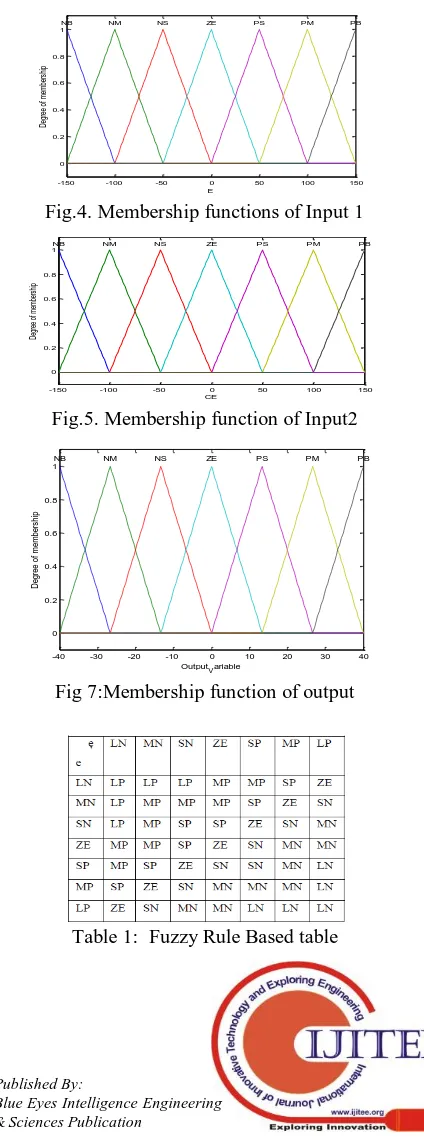
end goal to demonstrate the change in execution of DPFC. Reference estimation of DC voltage on DC Side and ordinary estimation of DC voltage on DC side of arrangement converter were utilized as fluffy controller inputs and the yield of fluffy controller is third consonant part of Direct Axis Component Reference arrangement infused voltage Fuzzification is where input factors are mapped onto fluffy factors each fuzzified variable as a specific participation work, here the data sources are fuzzified into seven fluffy sets seven enrollment capacities were utilized as a part of this paper which was trapezoidal and triangular fit as a fiddle. Both yield and info are fuzzified utilizing fluffy set which are viewed as seven they are Z(Zero), SP(Small - Positive ) , MP (Medium - Positive ) , LP(Large - Positive), SN(Small-Negative ), MN(Medium Negative), LN(Large - Negative)[13] which are said in figures 4, 5, 6 and Table 1.
-150 -100 -50 0 50 100 150
0 0.2 0.4 0.6 0.8 1
E
D
eg
re
e
of
m
em
be
rs
hi
p
NB NM NS ZE PS PM PB
Fig.4. Membership functions of Input 1
-150 -100 -50 0 50 100 150
0 0.2 0.4 0.6 0.8 1
CE
De
gr
ee
o
f m
em
be
rs
hi
p
NB NM NS ZE PS PM PB
Fig.5. Membership function of Input2
-40 -30 -20 -10 0 10 20 30 40
0 0.2 0.4 0.6 0.8 1
OutputVariable
D
eg
re
e
of
m
em
be
rs
hi
p
NB NM NS ZE PS PM PB
Fig 7:Membership function of output
[image:3.595.56.266.575.664.2]Enhancing the Performance of DPFC with Different Control Techniques
3.4 ANN controller of DC voltage
“Manufactured manmade Neural Network is a piece of the group of factual learning techniques motivated by organic sensory system and are utilized to appraise and surmised capacities that depends just on an extensive number of information sources. ANN is an interconnection of neurons which send messages to each other. The associations have numerical weights that can be tuned in view of understanding. This paper draws consideration on the multi-layer sustain forward ANN which that of the nonlinear multivariable capacity portrayal. The ANN is utilized for the mapping between the distinction of reference DC and Changed Value of DC on DC side of arrangement converter” for appropriate working conduction and ideal controller parameter [14,15].
IV. SIMULATION RESULTS
To reenact the DPFC with PI, SMC, FUZZY and ANN controllers a model in Matlab/Simulink is created. The
Simulink demonstrate is appeared in Fig.8. Reenactment works are completed to break down the DPFC execution in a transmission framework. A two transport control framework is considered for reenactment. Dynamic Power streams between the two transport frameworks are gotten by permitting distinctive stage between the two frameworks. DPFC comprises of 6-single stage arrangement converters and shunt controller. The parallel converter is a 1-ᴓ controller set between nonpartisan purpose of - Y transformer and strong ground, and on its opposite side is empowered by steady DC source. Here a transmission framework with a voltage of 380V and 50Hz is considered. The framework parameters in Simulink and estimated estimations of converter are appeared in table 2 and 3. The Simulation Results of proposed Simulink display are appeared in figures 9, 10, 11 and 12. The Conclusion execution of DPFC with various control strategies as far as Harmonic bending level is appeared in table 4.
B1 B2 B3 B4
-Y trans form er
-Y trans form er
Vs Vr
coupling trans form er Inverter
Vd,ref
Vq,ref
Vse (V)
I (A)
Pse
Qse V,I at side I (A)
Vse
V,I at side
P Q Discre te ,
Ts = 5e -005 s.
po we rgui
g A B +
-A B C
Three-Phas e Source1 A
B C Three-Phas e Source
A B C a b c A
B C a b c
A B C a b c A
B C a b c
A B C
a b c n2
A B C a b c n2
Scopes scopes
S eries Control
re fv,s h ,3
S hunt Control Signal(s)
Pulses PWM Generator
1 2 refv_sh_3
Goto2 Is h3
ref v_sh_3 i +
-3 2 1
6 5 4
Fig.8. Simulink Model of DPFC
Fig.9. Series injected Voltage
International Journal of Innovative Technology and Exploring Engineering (IJITEE) ISSN: 2278-3075,Volume-8 Issue-6, April 2019
0 0.05 0.1 0.15 0.2 0.25 0.3 0.35 0.4 0.45 0.5
-3 -2 -1 0 1 2 3
Time in Sec
v
o
lt
a
g
e
a
n
d
C
u
rr
e
n
t
Voltage and Current at Delta Side
Fig.11. Bus Voltage Current at delta side of the transformer
0 0.05 0.1 0.15 0.2 0.25 0.3 0.35 0.4 0.45 0.5
-8 -6 -4 -2 0 2 4 6
Time in Sec
L
in
e
c
u
rr
e
n
t
in
A
m
p
s
[image:5.595.308.549.43.728.2]fundamental component of line current
Fig.12. Line Current Due to step response
0 0.05 0.1 0.15 0.2 0.25 0.3 0.35 0.4 0.45 0.5
-7 -6 -5 -4 -3 -2 -1 0 1 2 3
Time in Sec
P
ow
er
in
W
at
t
Active and Reactive Power
[image:5.595.306.551.50.380.2]Fig.13. Both active and reactive power injected by series converter
Table 2: System parameters in Simulink
Para mete
r Abbreviation Value
Vs Sending end voltage 220 V
Vr Receiving end voltage 210 V
L Inductance component in line 6 mH
θ Angle between two end bus
voltages
[image:5.595.53.290.90.427.2]1o
Table 3: Measured Values of converter
Figures 14, 15, 16, 17 which represent THD percentage on injected voltage by series converter with different control techniques
0 0.1 0.2 0.3 0.4 0.5
-4 -2 0 2 4
Selected signal: 25 cycles. FFT window (in red): 10 cycles
Time (s)
0 200 400 600 800 1000
0 20 40 60 80
Frequency (Hz) Fundamental (50Hz) = 1.674 , THD= 19.98%
M
ag
(
%
o
f
Fu
nd
am
en
ta
l)
Fig 14: With PI Controller
0 0.1 0.2 0.3 0.4 0.5
-2 0 2
Selected signal: 25 cycles. FFT window (in red): 10 cycles
Time (s)
0 2000 4000 6000 8000 10000
0 20 40 60 80
Frequency (Hz) Fundamental (50Hz) = 1.595 , THD= 20.10%
M
ag
(
%
o
f
Fu
nd
am
en
ta
l)
Fig 15: with SMControl Method
0 0.1 0.2 0.3 0.4 0.5
-4 -2 0 2 4
Selected signal: 25 cycles. FFT window (in red): 10 cycles
Time (s)
0 2000 4000 6000 8000 10000
0 20 40 60 80
Frequency (Hz) Fundamental (50Hz) = 1.206 , THD= 21.49%
M
ag
(
%
o
f
Fu
nd
am
en
ta
[image:5.595.305.552.348.691.2]l)
Fig 16: With FUZZY control Method
0 0.1 0.2 0.3 0.4 0.5
-2 0 2
Selected signal: 25 cycles. FFT window (in red): 10 cycles
Time (s)
0 2000 4000 6000 8000 10000
0 20 40 60 80
Frequency (Hz) Fundamental (50Hz) = 1.796 , THD= 19.52%
M
ag
(%
o
f Fu
nd
am
en
ta
l)
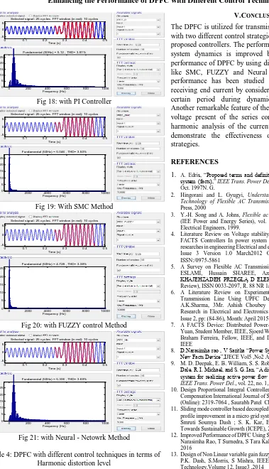
Fig 17: With Neural – Network control Method The Figure 18, 19, 20, 21 given below shows the THD Component of receving end current using different controll techniques
Symbol Description Value
Vsh,max Maximum shunt voltage by shunt converter 50 V
Ish,max Maximum shunt current by shunt converter 9 A
Ish,ref, Shunt converter reference third harmonic current
3A
Vsh,dc dc source supply 20V
Vse,max3 Series converter Maximum ac voltage at line side of
7 V
fsw Series Converter Switching frequency for
shunt and
6 kHz
Ise,max Series Converter peak ac current at line terminal of
[image:5.595.68.272.500.593.2] [image:5.595.40.286.618.735.2]Enhancing the Performance of DPFC with Different Control Techniques
0 0.1 0.2 0.3 0.4 0.5
-5 0 5
Selected signal: 25 cycles. FFT window (in red): 10 cycles
Time (s)
0 200 400 600 800 1000
0 5 10 15 20 25
Frequency (Hz) Fundamental (50Hz) = 5.12 , THD= 3.81%
M
ag
(%
o
f Fu
nd
am
en
ta
[image:6.595.64.443.35.695.2]l)
Fig 18: with PI Controller
0 0.1 0.2 0.3 0.4 0.5
-5 0 5
Selected signal: 25 cycles. FFT window (in red): 10 cycles
Time (s)
0 2000 4000 6000 8000 10000
0 5 10 15 20 25
Frequency (Hz) Fundamental (50Hz) = 5.046 , THD= 3.50%
M
ag
(%
o
f Fu
nd
am
en
ta
l)
Fig 19: With SMC Method
0 0.1 0.2 0.3 0.4 0.5
-5 0 5
Selected signal: 25 cycles. FFT window (in red): 10 cycles
Time (s)
0 2000 4000 6000 8000 10000
0 5 10 15 20 25
Frequency (Hz) Fundamental (50Hz) = 4.728 , THD= 3.38%
M
ag
(
%
o
f
Fu
nd
am
en
ta
l)
Fig 20: with FUZZY control Method
0 0.1 0.2 0.3 0.4 0.5
-5 0 5
Selected signal: 25 cycles. FFT window (in red): 10 cycles
Time (s)
0 200 400 600 800 1000
0 5 10 15 20 25
Frequency (Hz) Fundamental (50Hz) = 5.306 , THD= 3.69%
M
ag
(%
o
f Fu
nd
am
en
ta
l)
Fig 21: with Neural - Netowrk Method
Table 4: DPFC with different control techniques in terms of Harmonic distortion level
Type of Controller
Elementary Injected Voltage (%)
Current at receiving end (%)
PI 19.98 3.8
SMC 20.1 3.5
FUZZY 21.49 3.38
NEURAL NETWORK
19.5 3.6
V.CONCLUSION
The DPFC is utilized for transmission system in this paper with two different control strategies namely traditional and proposed controllers. The performance response in terms of system dynamics is improved by using controller. The performance of DPFC by using different control techniques like SMC, FUZZY and Neural technique the improved performance has been studied on injected voltage and receiving end current by considering their THD values for certain period during dynamic variations conditions. Another remarkable feature of the controller is that the line voltage present of the series converter is regulated. The harmonic analysis of the current and voltage waveforms demonstrate the effectiveness of the proposed control strategies.
REFERENCES
1. A. Edris, “Proposed terms and definitions for flexible ac transmission system (facts),” IEEE Trans. Power Del., vol. 12, no. 4, pp. 1848–1853, Oct. 1997N. G.
2. Hingorani and L. Gyugyi, Understanding FACTS : Concepts and Technology of Flexible AC Transmission Systems. New York: IEEE Press, 2000
3. Y.-H. Song and A. Johns, Flexible ac Transmission Systems (FACTS) (IEE Power and Energy Series), vol. 30. London, U.K.: Institution of Electrical Engineers, 1999.
4. Literature Review on Voltage stability phenomenon and Importance of FACTS Controllers In power system Environment. Global Journal of researches in engineering Electrical and electronics engineering Volume 12 Issue 3 Version 1.0 March2012 Online ISSN:2249-4596& Print ISSN:/0975-5861
5. A Survey on Flexible AC Transmission Systems (FACTS) Mahdiyeh ESLAMI, Hussain SHAREE, Azah MOHAMED, Mohammad KHAJEHZADEH PRZEGLĄ D ELEKTROTECHNICZNY (Electrical Review), ISSN 0033-2097, R. 88 NR 1a/2012
6. A Literature Review on Experimental Study of Power Losses in Transmission Line Using UPFC Device 1Akanksha Shrivas, 2Dr. A.K.Sharma, 3Mr. Ashish Choubey International Journal of Recent Research in Electrical and Electronics Engineering (IJRREEE) Vol. 2, Issue 2, pp: (84-86), Month: April 2015 - June 2015.
7. A FACTS Device: Distributed Power-Flow Controller (DPFC) Zhihui Yuan, Student Member, IEEE, Sjoerd W. H. de Haan, Member, IEEE, Jan Braham Ferreira, Fellow, IEEE, and Dalibor Cvoric, Student Member, IEEE
8. D.Narasimha rao , V Saritha “Power System Oscillation Damping Using New Facts Device”,IJECE Vol5 ,No2 April 2015.
9. M. D. Deepak, E. B. William, S. S. Robert, K. Bill, W. G. Randal, T. B. Dale, R. I. Michael, and S. G. Ian, “A distributed static series compensator system for realizing active power flow control on existing power lines,” IEEE Trans. Power Del., vol. 22, no. 1, pp. 642–649, Jan. 2007 10. Design Proportional Integral Controller Using Facts Device for Voltage
Compensation International Journal of Science and Research (IJSR) ISSN (Online): 2319-7064 , Saurabh Patel Chandra Kant Sahu
11. Sliding mode controller based decoupled control of STATCOM for voltage profile improvement in a micro grid system Swagat Pati ; K. B. Mohanty ; Smruti Soumya Dash ; S. K. Kar, Energy, Power and Environment: Towards Sustainable Growth (ICEPE), 2015 International Conference on. 12. Improved Performance of DPFC Using Sliding Mode Controller Method D Narasimha Rao, T Surnedra, S Tara Kalyani,IJECE Vol 6, No 5: October 2016
13. Design of Non Linear variable gain fuzzy controller for FACTS devices by P.K. Dash, S.Morris, S Mishra, IEEE Transaction on Control System Technology,Volume 12, Issue3 ,2014
14. A dynamic récurrent neural network for wide area identification of a multimachine power system with a FACTS device S. Mohagheghi ; G.K. Venayagamoorthy ; R.G. Harley, Intelligent Systems Application to Power Systems, 2005. Proceedings of the 13th International Conference on
15.DPFC performance with the comparsion of PI and ANN Controller By D Narasimha Rao , T Surendra , S