Probabilistic modelling of tool unbalance during cutting of
hard-heterogeneous materials: a case study in Ceramic Matrix
Composites (CMCs)
O. Gavalda Diaza, D.A. Axintea,∗, D. Novovicb
aRolls-Royce UTC in Manufacturing and On-Wing Technology, Faculty of Engineering, University of
Nottingham, NG7 2RD, UK
bManufacturing Technology, Rolls-Royce Plc, DE24 8ER, UK
Abstract
Compared to other materials, CMCs display a unique high hardness and heterogeneous
nature which are critically reflected during the drilling process where asymmetrical high
forces are suffered by the tool, resulting in an unbalance of the drill bit. Hence, this study
proposes a mechanistic approach where the hard nature resulting in high radial forces
is analytically studied and coupled with a probabilistic model where the heterogeneous
nature of CMCs is taken into consideration. This theoretical study results in an
in-depth understanding of the loading unbalance occurring on different tool sizes during
drilling of CMCs which can lead to a premature tool breakage. The nature of this
unique force that is assumed in the theoretical approach to influence the cutting of
hard-heterogeneous materials is experimentally validated by drilling a homogeneous and
a heterogeneous hard ceramics, i.e. a monolithic SiC and a SiC/SiC CMC. Moreover,
the model developed together the with drilling experiments with different tool diameters
result in an understanding of why small tool diameters suffer a premature tool breakage
when drilling difficult-to-machine CMCs.
Keywords: Machining, Ceramic Matrix Composites, Instabilities, Heterogeneous materials, Hard materials
2015 MSC: 00-01, 99-00
∗Corresponding author
1. Introduction
Ceramic Matrix Composites (CMCs) are a material choice as replacement to selected
high temperature metallic alloys in the aerospace industry [1] and are under
considera-tion for nuclear applicaconsidera-tion [2]. This success in high-value components is due to its high
mechanical and chemical performance in severe environments, especially at high
temper-atures. Non-oxide CMCs are normally formed by ceramic fibres (e.g. SiC or C fibres)
embedded in a ceramic matrix (e.g. SiC, C or Si3N4), producing a ceramic reinforced
ce-ramic which results in an improved fracture toughness compared to monolithic cece-ramics
[3]. The increase in demand of these materials in high-value sectors has developed the
need of understanding and optimising the machining process. Nevertheless, due to its
heterogeneous and hard nature, the mechanical machining can be challenging, in
partic-ular when small tools need to withstand high cutting forces. Several authors reported
short tool life when mechanically machining CMCs [4]; as such, it was concluded that
micro-holes could not be machined in hard CMCs probably due to the poor surface
qual-ity achieved and the premature tool breakage [5]. Nevertheless, an in-depth analysis of
the phenomena occurring when machining hard-heterogeneous CMCs and how the tool
size can be affected by the material heterogeneous structure has not yet been reported
in the literature.
Several non-conventional machining techniques have been experimentally tested in
hard CMCs [6]. Pulsed Laser Ablation (PLA) has been studied due to the promising
surface finishing that can be produced; nevertheless, to achieve higher machining rates
and to allow the debris to be removed, high powers are needed that could result in
thermal material damages such as oxidation and degradation of the non-oxide ceramics
[5, 7]. Similar thermal damages were observed when using Electro Discharge Machining
(EDM) which proved to show very slow material removal rates due to the low conductivity
of the CMCs’ structure [8]. It could be commented that the thermal damages initiated
during PLA and EDM are due to the anisotropic thermal properties of CMCs which
facilitates temperature builds-ups in specific regions of the workpiece. Abrasive
water-jet machining (AWJ) was reported as a good technique to machine hard ceramics and
CMCs [9, 10]; nonetheless for hole-making applications the material tends to suffer large
delaminations due to the initial impact of the jet with the workpiece laminated structure
[11]. The feasibility of Rotary Ultrasonic Machining (RUM) and ultrasonic drilling have
been reported in the literature concluding that compared to conventional machining, the
cutting forces can be reduced [12, 13]. While this work provides useful application data,
the authors believe that a fundamental study of how the conventional drilling operation,
as a readily available process, is affected by these hard-heterogeneous materials is needed.
Conventional machining process in CMCs has hardly been reported in the literature.
Gavalda Diaz and Axinte [14] reported a mechanical understanding of the mechanisms
governing the orthogonal cutting process of CMCs. However, the application of this
understanding has not yet been evaluated to non-orthogonal machining process such
as drilling, where a more complex scenario is faced. The conventional drilling of other
heterogeneous materials such as Carbon and Glass Fibre Reinforced Plastic (CFRP and
GFRP) has been more extensively studied [15, 4]. Nevertheless, as compared to CMCs
the constituents of PMCs generally possess a much lower hardness, the possible existence
of radial force components are difficult to capture and might not be a significant aspect.
A few researchers [16, 17] explained that in the orthogonal cutting of PMCs, an oscillation
force could appear due to the composites’ heterogeneous nature and continuous fracture
mechanism between the fibre and matrix. This influence is therefore existent and needs
to be in-depth studied in drilling of heterogeneous and hard materials, especially at small
tool diameters when this can result in high instabilities leading to a premature breakage
of the tool with further negative influence in the surface integrity.
When drilling monolithic materials, the instabilities are mainly caused by the whirling
of the drill [18]. A few researchers [18, 19] modelled the vertical and lateral vibration that
due to the chattering appear with the tool rotation. Nonetheless, in difficult-to-machine
CMCs, it could be commented that the heterogeneous and hard nature of the material
can result in asymmetric and variable forces, being the main cause of lateral and vertical
instabilities.
To address the identified research gaps, in this paper, a novel approach to understand
how the heterogeneous and hard nature of CMCs affects the tool unbalancing during the
machining process is proposed. The heterogeneous nature of the material structure is
de-fined by using stochastic variables resulting in a probabilistic approach of the mechanical
comprehen-sion how the tool size affects the stability; which is certainly influenced by the material
nature (e.g. size of the tows, matrix region and porosities) and the tool rigidity itself.
The main aim is then to provide an in-depth understanding on why small diameter drills
suffer from an unbalancing resulting in a premature tool breakage. Further, the paper
aims to define a methodology that could specify the critical diameter which the drills
can withstand the cutting forces. Hence, this work offers for the first time a coupled
mechanistic-probabilistic approach that relates the hard-heterogeneous nature of CMCs
upon cutting force distribution. This results in a novel framework for future
machin-ing models where the hard-heterogeneous nature of materials has a crucial effect on the
process.
2. Influence of scaling the CMCs’ heterogeneous constitutive elements upon cutting process
The relationship between the nature of the CMCs and the tool size is studied in the
following section by characterising how the drill main cutting edges contact alternating
constituents of the CMC and how this influences the tool stability.
2.1. Effect of the CMCs heterogeneous nature on the drilling performance
Woven reinforced materials such as CMCs can be characterised by three different
constituents: fibres, matrix and porosities [4]. Particularly in CMCs, due to the complex
manufacturing method followed and especially during the stage of Chemical Vapour
Infiltration (CVI), big porosities can be found within the material [20] and therefore, they
need to be considered when seeking an in-depth understanding of the cutting mechanism.
Fig.1 represents a typical microstructure of a 2D woven CMC material, having plies with
fibre-rich areas (warps and wefts), matrix-rich areas and porosities.
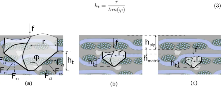
In the force diagram for a free-body drill bit (Fig.2), when drilling with a feed rate
(f) on a homogeneous material, it can be observed that due to the point shape of the
tool (defined by the half-point angle, ϕ) two radial forces with opposite directions are
created in a X-Z plane: Fx1 and Fx2. In the specific case of a homogeneous material,
the radial forces have opposite directions but the same or very similar magnitude, and
therefore:
Figure 1: Scheme of a 2D woven structure with a close-up showing the ply area.
[image:5.595.201.395.281.448.2]Fx,resultant=Fx,1−Fx,2→0 (1)
Figure 2: Simplified diagram of the forces appearing in a twist drill within a homogeneous material in a X-Y plane.
However, in the case of CMCs, due to their heterogeneous nature, the radial forces still
have opposite directions but might not have the same magnitude. This could occur due
to the different material constituents (fibres, matrix or porosities) that are in contact
with the main cutting edge (l) at each instant of the machining process, as shown in
Fig.3a. Therefore, in contrast with homogeneous structures, when drilling composite
materials the resultant force might not be null anymore. Moreover, asFx,1 andFx,2are
components of the thrust force (Ft,1 and Ft,2), for hard materials such as CMCs that
display high forces, the magnitude of these radial components is also increased, producing
a greater level of imbalance of the forces in x direction. Hence, it can be postulated that
Fx,resultant=Fx,1−Fx,26= 0 (2)
Furthermore, as shown in Fig.3, the relationship between the drill diameter and the
heterogeneous structure generates a scaling effect on the stochastic distribution of fibre,
matrix and porosity content against the main cutting edge of the drill, which could
affect the magnitude of the radial force. Considering thathmatrix is the thickness of the
matrix-rich region andhply is the thickness of the ply, the three main scaling scenarios
(dependent on the drill diameter) at which cutting takes places are as follows:
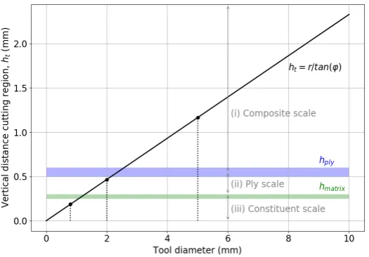
i. Cutting at composite scale: ht> hply (Fig.3a)
ii. Cutting at ply scale: hmatrix < ht< hply (Fig.3b)
iii. Cutting at constituent scale: ht< hmatrix (Fig.3c)
Whereht is the length of the cutting region, considered along the feed direction, that
depends on the tool diameter and the point angle:
ht=
r
[image:6.595.108.492.422.580.2]tan(ϕ) (3)
Figure 3: Simplified diagram of the forces appearing in a twist drill within a heterogeneous material for (a) composite scale (ht > hply), (b) ply scale (hmatrix < ht < hply) and (c) constituent scale
(ht< hmatrix) showing how the relative content of fibres and matrix might vary depending on the tool
size.
To better understand the influence of the heterogeneous nature of CMCs and how
the tool diameter affects the potential imbalance of the drill, a probabilistic analysis
that defines the randomness found within a woven structure using stochastic variables is
proposed in the next section.
2.2. Probabilistic approach of the radial force resultant when drilling the heterogeneous constituents of CMCs
As aforementioned, the composite structure can be characterised by the fibre-rich
region, matrix-rich region and porosities. In terms of relative content (c):
ccomposite=cf ibre+cmatrix+cporosity= 1 (4)
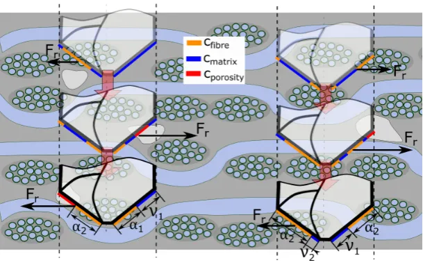
As shown in Fig.4, the relative content of fibre, matrix and porosity is changing along
the hole and it also varies depending on where the hole is machined. Therefore, two
stochastic variables are defined to describe the structure of the material; the relative
content of fibre is defined asαwhile the relative content of matrix asν. Hence, the total
relative content of material in contact with the main cutting edge (l) at a specific instant
of the drilling process (t) can be defined as:
ccomposite(l, t) =α+ν+ (1−α−ν) (5)
where l is the length of the drill main cutting edge which can be described in function
of the drill radius (r) as:
l= r
sin(ϕ) (6)
It is therefore clear that, depending on how the material is distributed along the
drilling path, the tool might encounter from different (non-zero) values of the resultant
radial forces. Due to the stochasticity ofαandν, a probabilistic approach defining when
the resultant radial force tends to be null depending on the main cutting edge length (l),
can offer an understanding of how the tool diameter affects the level of unbalance of the
system.
The tool is unbalanced if the relative content of fibre and matrix on one cutting edge
(α1 and ν1 respectively) are not identical or very similar to the contents on the other
cutting edge (α2 andν2).
P(Fradial= 0) =P(A and B) (7)
Figure 4: Diagram representing how the relative content of fibre (α) and matrix (ν) changes along the hole and depending on where the hole is machined within the CMC workpiece.
α2) and the relative content of matrix (ν1andν2):
A→(α1=αi, α2∈xf) f or αi= [0,1]
B→(ν1=νi, ν2∈yf) f or νi= [0,1]
(8)
wherexf andyf are defined as the smallest variation of content of fibre and matrix
which does not affect the radial force and therefore, it remains constant for a specific
CMC and depends exclusively on the constituents’ mechanical properties (e.g. different
hardness between the fibres and matrix). As A and B are dependent events, Eq.7 can be
written as:
P(A and B) =P(A)P(B|A) (9)
For the analysis, the stochastic variables (α andν) are treated as discrete variables
with a minimum step of 0.01, which is considered to be small enough to describe the
physical variations of content of fibres and matrix that can affect the tool stability.
Thus, the probabilityP(A) can be calculated as:
P(A) = 1 X
α1=0
α1+xf X
α2=α1−xf
fαα(α1, α2) (10)
and the probabilityP(B|A) can be calculated as:
P(B|A) = 1 X
ν1=0
ν1+yf X
ν2=ν1−yf
fνν(ν1, ν2) (11)
Therefore, the probability of having null radial forces can be described as:
P(Fradial= 0) = 1 X
α1=0
α1+xf X
α2=α1−xf
fαα(α1, α2) 1 X
ν1=0
ν1+yf X
ν2=ν1−yf
fνν(ν1, ν2) (12)
wherefααand fνν are the bivariate probability density function (PDF) forα1−α2
andν1−ν2that can be computed by simulating the heterogeneous structure of a CMC.
As previously shown in Fig.3, the length of the main cutting edge l (which depends on
the tool diameter) could have an influence on the distributionsfααand fνν that needs
to be considered for the calculations. Then, with the aim of obtaining the probability
of the tool having a radial force, the PDFs ofα1−α2 andν1−ν2 have been obtained
for different tool diameters by simulating the heterogeneous structure of a CMC and
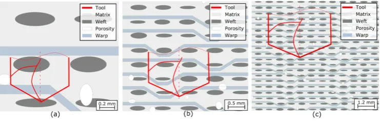
randomly placing the two main cutting edges within the material. The structure of a
0/90 five-hardness satin (5HS) CMC material was chosen as a scenario to be represented
in the simulation as it is one of the most used reinforcement structure in high temperature
CMCs, due to its high mechanical performance [21]. As shown in Fig.5, the structure of
the CMC has been modelled by placing wefts, warps and porosities within a matrix in
the following way:
• The wefts have been modelled as ellipses [22] with randomised minor (between 50
and 100µm) and major (between 250 and 300µm) axes. The centre of the ellipse
has also been slightly randomized in x and y direction from the weft centre.
• The warps have been simulated as polygons which wave the already defined wefts
structure and a random thickness (between 50 and 100µm)
• The porosities have been modelled as ellipses, as they reproduce similar geometries
as the ones observed in the real CMC structure, with random coordinates of the
[image:10.595.116.487.275.394.2]centre point and a random minor and major axis (between 100 and 250µm).
Fig.5a, b and c show these scenarios with a random placement of the tool main cutting
edges for a 0.8 mm, 2 mm and 5 mm drill respectively.
Figure 5: Plots of the simulation showing the random structure of a 5HS satin with a random placement of drill sizes which correspond to cutting at (a) constituent scale (ht< hmatrix) , (b) ply scale (hmatrix<
ht< hply) and (c) composite scale (ht> hply) that allows a computation of the bivariate distributions
of fibres (fαα) and matrix (fνν). Note: the scales of the figures are different
The simulation shown in Fig.5 has been run millions of times by generating each
time a new random heterogeneous structure and by placing the drill arbitrarily in order
to have a large enough and representative population and consequently, obtain accurate
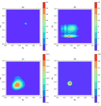
bivariate PDFs. Fig.6 shows thefαα obtained for a 0.8mm, 2 mm, 5 mm and 50 mm
drill respectively, where the x axis represents the relative content of fibres on one cutting
edge and y axis on the other one. The PDF suffers an interesting evolution when the
diameter is increased: on the one hand, for a 0.8 mm diameter (Fig.6a), the function
obtained results in very punctual values (almost behaving as a boolean function) at (0,
0) and (0.6, 0.6), which translates in hitting only matrix or 60% of fibres in both sides of
the tool respectively. On the other hand, when the diameter is progressively increased
from 2 mm to 50 mm (Fig.6b, Fig.6c and Fig.6d), the functions evolve from punctual
values to bi-variate normal distributions where the standard deviations in both x and y
are reduced when increasing the diameter.
Figure 6: Bivariate probability density functions of having a relative amount of fibres on one main cutting edge (α1) and on the other cutting edge (α2) of the tool (fαα) for a (a) 0.8mm (b) 2 mm (c) 5
mm and (d) 50 mm drill.
The drastic evolution between the PDFs obtained for the 0.8, 2 and 5 mm diameter
drill has a clear explanation based on the scaling effect caused by the CMC’s
hetero-geneous nature. As previously mentioned, the characteristic lengths of the material
heterogeneous nature (thickness of the plyhply and the thickness of the matrix region
hmatrix) compared to the vertical length of the cutting region (ht) should affect the
PDFs. In this study, the three tool diameters chosen, represent the different scenarios
previously mentioned where (i)ht> hply for a 5 mm drill (ii)hmatrix< ht< hply for a
Figure 7: Tool diameter versus the vertical distance of the cutting region (ht) obtained with Eq.3.
The blue and green bands represent the characteristic length of the ply (hply) and matrix (hmatrix)
respectively. The three diameters studied in this work (0.8, 2 and 5 mm) are examples of the three cutting scaling scenarios at (i) composite, (ii) ply and (iii) constituent scales.
The approach defined in this section results in a probabilistic explanation relating
the influence of the tool diameter with the radial forces that could appear when drilling
CMCs. Nevertheless, depending on the magnitude of this force a premature tool failure
can occur and therefore a mechanical approach where the rigidity of the tool and how
this radial force affects the tool unbalancing is needed and proposed in the following
section.
2.3. Simplified probabilistic-mechanical approach to understand the tool fracture when drilling CMCs
When machining hard-homogeneous materials, which result in high thrust forces, the
two main failure mechanisms that drills can suffer are either due to the compressive stress
exceeding the strength of the material or due to buckling, depending on the slenderness
of the drill [23]. However, when machining highly heterogeneous structures with
con-stituents of various hardness, the tool suffers a deflection due to the non-homogeneous
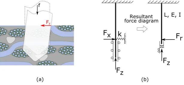
material structure, due to the radial force component previously introduced (Fig.8a).
This radial force causes a bending moment and, as the buckling does not depend on the
to a reaching of the yield strength in tension [24]. Fig.8b, shows a schematic of how the
drill is deflected and creates a contact with the work-piece walls, resulting in a radial
force (Fr).
Figure 8: (a) Schematic showing the nature of the radial forces acting on a drill bit while machining CMCs and (b) mechanical approach of the forces acting in the immersed drill due to the material heterogeneous structure.
The stresses suffered from the tool are then caused by the radial force (bending stress,
σx,bend) and by the vertical force (compressive stress, σx,comp). The stress due to the
bending moment can be calculated using the following equation:
σx,bend=
Mzy
I (13)
Solving the hyperstatic system, it is found that the momentum (Mz) acting on the
clamping point of the drill is equal toFrL/2, whereFr is the radial force, r is the radius
of the drill and L is the cutting tool length which decreases with the feed rate (f) and
the cutting time (t): L=L0−f t. We can then rewrite Eq.13 as :
σx,bend=
FrLr 2Ixx
= Fr(L0−f t)r 2Ixx
(14)
The quadratic moment (IxxandIyy) for a twist drill can be calculated as [25]:
Ixx=Ixxcos2(
r lβ) +I
yysin2(r
lβ)
Iyy =Iyycos2(
r lβ) +I
xxsin2(r
lβ)
[image:13.595.145.453.201.344.2]whereIxx=r4 6 andI
yy= 2r4
3 if the drill twisting section is considered as a rectangle
of 2r x r.
The stress due to the compression effect can be calculated as:
σx,comp=
Fz
2r2 (16)
whereFz is the vertical force. Therefore, the total tensional stress suffered from the
tool at the external part can be obtained by subtracting the compressive stress (Eq.16)
to the bending stress (Eq.14):
σx=
Fr(L0−f t)r 2Ixx
− Fz
2r2 (17)
As discussed in the previous section, the heterogeneous nature of the material (defined
by the stochastic variables αandν) affects the forces and therefore,Fr and Fz should
also be considered stochastic variables. Moreover, from Eq.17 it can be observed that
as the total stressσxdepends on both, the radial and vertical force (Fr andFz), it also
needs to be treated as a stochastic value, meaning that the tool suffers an oscillating
stress, depending on the tool position into the heterogeneous CMC structure.
The stochasticity of the radial and vertical forces appearing when drilling
hard-heterogeneous materials such as CMCs, can then be written as:
Fr= (Ft,1−Ft,2)cosϕ
Fz= (Ft,1+Ft,2)sinϕ
(18)
where Ft,1 and Ft,2 are the thrust forces shown in Fig.2, and can be analytically
defined as:
Ft,1=W(Mfα1+Mmν1)
Ft,2=W(Mfα2+Mmν2)
(19)
whereMf andMmare constants that depend on the material properties of the fibres
and matrix regions respectively; and W is a function that describes the efficiency of the
cutting tool considering the evolution in wear that drills might suffer due to the hard
nature of the materials studied. Combining Eq.18 and Eq.19:
Fr=W(Mf|α1−α2|+Mm |ν1−ν2|)cos(ϕ)
Fz=W(Mf(α1+α2) +Mm(ν1+ν2))sin(ϕ)
(20)
Eq.20 is therefore an analytical approach where the radial and vertical forces could be
calculated by using the previously defined stochastic variablesαandν and that models
the oscillating nature of the force signals. However, obtaining the function of wear W
and the constantsMf andMmis not straightforward due to to the fact that during the
experiments the random variablesα andν can not be controlled and specific data can
not be obtained. Hence, the aim of Eq.20 is not to provide a force model but just give an
analytical explanation of the phenomena that induces stochasticity in the stress suffered
by the tool.
To validate the effect of the heterogeneous structure on the tool instability, Eq.17 will
be used. However as the stress has been defined as a stochastic variable, the tool failure
should be calculated in terms of having a peak of stress higher than the value of yield
strength of the tool material:
max(σ)> σyield (21)
With the probabilistic approach defined to understand the heterogeneous nature and
the simplified mechanical approach developed to relate the high hardness to the
heteroge-neous structure, the drilling of hard-heterogeheteroge-neous materials (e.g. CMCs) has been
ana-lytically studied, providing a theoretical understanding of how the CMC microstructural
heterogeneity can influence the tool unbalancing and lead to premature tool breakage.
The strength of this study resides in the fact that the microstructure analysis can be
adapted to consider bigger/smaller tows, more/less porosities or different reinforcement
structures (e.g. plain, twill, 8HS, etc). Moreover, as the characteristic length of the main
cutting edge (l) is considered in this study, an understanding of which size threshold
leads to a premature tool breakage can be studied with the help of some experimental
3. Experimental methodology
The material used to obtain experimental data for this work was a Chemical Vapor
Infiltrated Melt Infiltrated (CVI-MI) SiC/SiC CMC which is one of the most
difficult-to-machine CMC due to its high hardness of both, fibres and matrix. The SiC fibres forming
the CMC were Hi-Nicalon (≈10-15µm diameter[21]) coated with a Boron Nitride (BN)
and waved in tows within a 5 Hardness Satin (5HS). The CMC material specification
and its properties are detailed in [26]. In terms of volume fraction, typically CVI-MI
SiC/SiC materials reach values of relative volume of matrix and fibres of 60-65% and
30-35 % respectively [21]. Because the objective of this work is to understand how the
heterogeneous nature of hard materials affects the machining process, a homogeneous
SiC simulating the material found in the matrix of the CMC was also used during the
machining trials.
A commercially available standard twist drill with a point angle of 130◦, with a CVD diamond coating was used in three different diameters: 0.8, 2 and 5 mm. These three
diameters could represent three typical values of small, intermediate and large tools used
in the precision machining industry and it has been previously shown that these values
suffer different PDFs due to the scaling effect created by the CMC structure.
The CNC machine centre used for the experiments was a 5-axis Hermle C800U offering
a high rigidity and stable cutting. Cutting parameters used for the tests were generic
baseline parameters to obtain a gentle cutting condition in brittle-hard materials, not
necessary optimised for CMC materials (f = 2mm/min and v = 3000 rpm) keeping the
feed rate constant for all the diameters and using coolant. The samples of CMC and
homogeneous ceramic were plates of 70 x 70 x 5mm mm clamped in compression from
two sides. The cutting forces were measured while drilling perpendicular through-holes
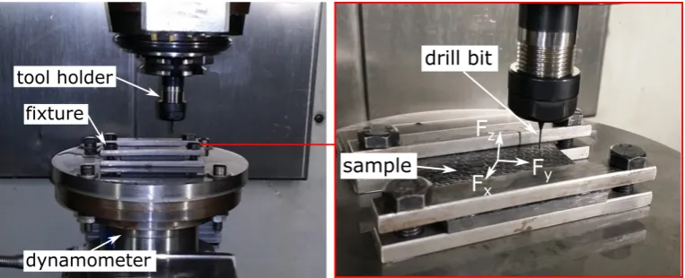
with a 4-component (Mz,Fz,FyandFx) dynamometer (Kistler 9272). A picture of the
setup is shown in Fig.9.
After the drilling trials, the drill bits and the machined surfaces were analysed by
Scanning Electron Microscopy (Philips XL30 ESEM-FEG) to observe wear and fracture
mechanism of the drill.
Figure 9: Machining centre and set-up used to perform experimental tests to validate the theoretical work.
4. Results and discussion
In this work, the existence of a radial force caused by the heterogeneous nature of
CMCs and affecting the stability of the tool is proposed and discussed. To validate that
this hypothesis was accurate, the thrust and the radial forces were measured while drilling
holes in a SiC/SiC CMC (heterogeneous material) and a SiC ceramic (homogeneous
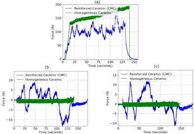
material). Fig.10 shows the results for these tests, resulting in a clear difference between
the forces obtained for the CMC and the homogeneous ceramic: in Fig.10a it can be
observed how in the CMC, the vertical force has an oscillating nature that does not
appear in the homogeneous ceramic. Moreover, Fig.10b and Fig.10c show how for a
homogeneous ceramic the radial force is almost null and constant, while in the CMC it
has an oscillation component that changes completely the tool condition.
Based on these results, it is possible to state that the heterogeneous nature of CMCs
affects the cutting process, resulting in radial forces that affect the balancing of the drill.
Thus, as hypothesised in Eq.2, the two radial force components need to be different: Fx,1
6
=Fx,2.
Using Eq.12 and the PDFs obtained from the simulation, the probability of having
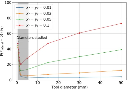
a null radial force depending on the values of xf and yf can be computed and has
been plotted in Fig.11. In this graph, it can be observed that the values of probability
Figure 10: Force signals obtained during the drilling of a CMC (heterogeneous material) in blue and ceramic (homogeneous material) in green in (a) z direction (Fz), (b) y direction (Fy) and (c) in x
direction (Fx).
decreases for diameters between 0.6 and 2 mm and afterwards increases with rate that
highly depends onxf andyf. The reason for the first drop in probability is due to a higher
characteristic size of the material heterogeneous nature than the cutting length region
(hmatrix > ht), resulting in very different punctual probability density distributions, as
shown in Fig.6a. However, when the vertical cutting length (ht) is higher than thehply
the probability increases again.
To experimentally confirm the theoretical results, the three different tool diameters
(0.8, 2 and 5 mm) were tested as a representative diameters of the different conditions
studied. Fig.12 shows how for the three diameters the normalised radial force has an
oscillating nature, however, for the 0.8 mm drill the force seems to definitely have more
values where the force magnitude tends to zero. Certainly, the 2 mm drill and the 5 mm
drill have similar oscillation behaviours with less values tending to zero. It can be
Figure 11: Results obtained from Eq.12: probability of having a null radial force (P(Fr= 0)) in front of
the tool diameter and for different values of the constantsxf andyf, which were defined as the smallest
variation of content of fibre and matrix which does not affect the radial force.
fore concluded that the probability of having a lateral force decreases when increasing
the diameter between 0.8 and 2 mm but it remains considerably similar between the 2
and 5 mm tools. Hence, it is difficult to establish exact values ofxf and yf as between
the range (0.01-0.05) this tendency is more or less observed.
As the radial component is present when drilling holes in CMCs for the diameters
studied, the tool should tend to have an unbalancing component and therefore, the
mechanical model where the rigidity of the tool and the force magnitude are considered
needs to be evaluated for a better understanding of the origin of this instability.
To comprehend the tool life and therefore the hypothetical premature tool breakage of
the drills, 20 holes were intended to be performed with the three different tool diameters.
The results showed that the drill of 0.8 mm diameter fractured after 4 holes while the 2
and 5 mm diameter drills did not break after 20 holes. A SEM picture of the cutting area
from the⌀0.8 mm drill after 4 holes and one from the⌀2 mm and the⌀5 mm drill after
20 holes are shown in Fig.13a, Fig.13b and Fig.13c respectively. It can be observed that
for the⌀0.8 mm drill, the tool fracture occurs before being fully worn, while the other
diameters suffer a high wear without reaching the tool failure. It is therefore appreciated
Figure 12: Normalised radial force signal (Fr) obtained from the drilling experiments with a 0.8 mm
drill, 2 mm drill and 5 mm diameter tools.
forces create an unbalancing effect, sufficient to reach the failing point. On the other
hand, when the diameter of the tool is increased and therefore its rigidity, the radial force
appearing during drilling is not enough to break the tool and the failure mechanism is
not dominated by tool instability but because of tool wear.
Figure 13: Tool damage evaluation showing SEM images of (a) a 0.8 mm drill after 4 holes (b) a 2 mm drill after 20 holes and (c) a 5 mm drill after 20 holes.
The stress suffered for each tool diameter differs and needs to be calculated in order to
understand why this premature tool fracture occurs. As developed in Section 2, the total
tensional stress suffered by the tool can be calculated by using Eq.17. Fig.14 shows the
stress along the hole suffered for the three different tools and the values of yield strength
(which varies from 2060-2270 MPa) and tensile strength (which varies from 2430-2680
[image:20.595.107.491.454.553.2]MPa) for a WC-12%wt Co [27], which is representative of the tool core material. In
the case of the 0.8 mm diameter tool, when machining the fourth hole, the tool reaches
close values to the yield strength and is not far from the tensile strength, meaning that
the tool might be suffering local plastic deformation which leads to a progressive failure.
Nevertheless, for the other diameters (2 and 5 mm) the stress is much lower and the
values of material strength are far being reached, and therefore the tool is working in a
[image:21.595.166.432.273.449.2]more comfortable zone of stress.
Figure 14: Stress distribution along the hole obtained by using Eq.17. The blue line represents the 4th hole for a 0.8 mm tool, the yellow line the 10th hole for a 2 mm tool and the green line the 10th hole for a 5 mm tool.
Looking more in detail at the history of stress suffered by the 0.8 mm tool before
the fracture, Fig.15 shows how this stress is progressively incremented (due to local tool
wear) resulting in a maximum value when machining the 4th hole.
Moreover, to compare how the drill could be fractured when drilling a standard
hard-homogeneous material (which does not display a radial force component), the well-known
calculations of compressive strength and buckling with no eccentricity have been checked:
• Compressive strength of the tool material (WC-12%wt Co) : 3810 - 4200 MPa [27]
Figure 15: Stress history calculated using Eq.17 for the 0.8 mm drill when drilling 4 holes into a difficult-to-machine CMC.
of 15 mm as similarly done in [28, 29] :
σc,buckling =
Fc,buckling
A =
2.046π2EI
2L2r2 = 676.6−711.4M P a (22)
where the Young Modulus (E) for a WC-12%wt Co is 565-594 GPa [27]. The maximum
compressive stress suffered by the tool when machining the last hole can be calculated
using Eq.16 and results in a stress of 171.9 MPa. Therefore, it can be corroborated that
the tool is not braking because buckling nor compressive strength but just because of the
bending created by the radial force that appears due to the hard-heterogeneous structure.
Moreover, looking at the fracture section of the broken tools (Fig.16) the fracture shape
observed is exactly the same as the one observed previously in the literature for static
failure tests of micro-drills in bending [29].
This section has shown that the probability of having a radial force component can
be higher for very small diameters, however the values of probability are still smaller
than 40 % and therefore, using the mechanical approach, it can be concluded that small
drills (in this study a 0.8 mm) suffer higher stresses that lead to a premature tool failure.
Figure 16: Shape of the fracture section obtained for the 0.8 mm drill after breaking due to a bending solicitation.
5. Conclusions
In contrast with other composite materials or homogeneous ceramics, CMCs possess
the double challenge of having a hard-heterogeneous nature that affects the machining
process. The work presented here aims to couple these two challenging properties by
developing a probabilistic and mechanical approach that allows an understanding of the
unbalancing that cutting tools (in this work drill bits) can suffer when machining CMCs
and that can lead to premature tool breakage. The main conclusions of this work are:
• A radial force component suffered when drilling that does not appear in
homoge-neous materials nor heterogehomoge-neous materials of reduced hardness, has been reported
in this paper for hard-heterogeneous materials such as CMCs, which are a trendy
material choice for high temperature applications.
• Two stochastic variables have been used to define the random relative content
of fibres (α) and matrix (ν) that the drill main cutting edges face at a specific
instant of the drilling and that allow to develop a probabilistic approach of the
machining process. To obtain specific data, the structure of a CMC was modelled
by simulating random positioning and sizes of warps, wefts and porosities within a
matrix. This simulation led to the bivariate probability density distributions that
define the relative content of fibres and matrix that one cutting edge of the drill
faces compare to the other one. It is found that the probability of having a null
lateral force is higher for very small diameters and that after a certain value, the
• A simplified mechanical approach that couples the hard nature of the material
while considering the stochasticity of the heterogeneous structure of the CMCs has
been developed, leading to a calculation of the tensional stress that appears due
to the radial force component and that the tools suffer depending on its diameter.
It is found that for a 0.8 mm diameter, the tool reaches values of yield strength,
while for bigger diameters (e.g. 2 mm and 5 mm) these critical values are far from
being reached.
• Drilling trials with a CMC and a monolithic ceramic and by using different tool
diameters (0.8, 2 and 5 mm drills) have driven to an understanding of how the
radial force appears and evolves when machining hard-heterogeneous materials.
The results of these trails have allowed to verify the applicability of the theoretical
approaches.
• The minimum tool diameter that does not suffer a premature tool breakage from
lateral unbalancing while machining a SiC/SiC for a specific cutting conditions has
been found, providing useful information to the field of machining hard-heterogeneous
materials such as CMCs.
The applicability of this work could also be transferred to other machining process
such as reaming, counter boring, grinding or turning where symmetric forces are expected
during the cutting process.
References
[1] Patrick Spriet. CMC Applications to Gas Turbines. InCeramic Matrix Composites, chapter 21, pages 591–608. John Wiley & Sons, Inc., Hoboken, NJ, USA, oct 2014.
[2] C´edric Sauder. Ceramic Matrix Composites: Nuclear Applications. InCeramic Matrix Composites, chapter 22, pages 609–646. John Wiley & Sons, Inc., Hoboken, NJ, USA, oct 2014.
[3] Christine Droillard and Jacques Lamon. Fracture Toughness of 2-D Woven SiC/SiC CVI-Composites with Multilayered Interphases, 1996.
[4] R Teti. Machining of Composite Materials.CIRP Annals - Manufacturing Technology, 51(2):611– 634, 2002.
[5] Weinan Li, Ruoheng Zhang, Yongsheng Liu, Chunhui Wang, Jing Wang, Xiaojun Yang, and Laifei Cheng. Effect of different parameters on machining of SiC/SiC composites via pico-second laser.
Applied Surface Science, 364:378–387, 2016.
[6] Z J Pei. Non-traditional drilling of SiC based ceramic matrix composites : a literature review Pengfei Zhang * Qiang Feng Wenwu Zhang. Int. J. Machining and Machinability of Materials, 10(3):235–259, 2011.
[7] S. Costil, S. Lukat, C. Langlade, and C. Coddet. Surface modification of ceramic matrix composites induced by laser treatment.Applied Surface Science, 255(5 PART 1):2425–2432, 2008.
[8] Chenjun Wei, Li Zhao, Dejin Hu, and Jun Ni. Electrical discharge machining of ceramic matrix composites with ceramic fiber reinforcements. pages 187–194, 2013.
[9] D. S. Srinivasu, D. A. Axinte, P. H. Shipway, and J. Folkes. Influence of kinematic operating pa-rameters on kerf geometry in abrasive waterjet machining of silicon carbide ceramics.International Journal of Machine Tools and Manufacture, 49(14):1077–1088, 2009.
[10] G Hamatani and M Ramulu. Machinability of High Temperature Composites by Abrasive Waterjet.
Transactions of the ASME, 112(October):381–386, 1990.
[11] H. Hocheng, N. H. Tai, and C. S. Liu. Assessment of ultrasonic drilling of C/SiC composite material.
Composites Part A: Applied Science and Manufacturing, 31(2):133–142, 2000.
[12] Z. C. Li, Y. Jiao, T. W. Deines, Z. J. Pei, and C. Treadwell. Rotary ultrasonic machining of ceramic matrix composites: Feasibility study and designed experiments. International Journal of Machine Tools and Manufacture, 45(12-13):1402–1411, 2005.
[13] Kai Ding, Yucan Fu, Honghua Su, Yan Chen, Xizhai Yu, and Guozhi Ding. Experimental studies on drilling tool load and machining quality of C/SiC composites in rotary ultrasonic machining.
Journal of Materials Processing Technology, 214(12):2900–2907, 2014.
[14] D.A Axinte O Gavalda Diaz. Towards understanding the cutting and fracture mechanism in ceramic matrix composites.International Journal of Machine Tools and Manufacture, 118-119(March):12– 25, 2017.
[15] DeFu Liu, YongJun Tang, and W. L. Cong. A review of mechanical drilling for composite laminates.
Composite Structures, 94(4):1265–1279, 2012.
[16] Jiawei Mei, Oriol Gavalda Diaz, and Dragos A. Axinte. An approach on capturing the influence of the stochasticity of fibre distributions for modelling the variability of cutting forces in composite materials. Composites Part B: Engineering, 125:27–38, 2017.
[17] G. Venu Gopala Rao, P. Mahajan, and N. Bhatnagar. Micro-mechanical modeling of machining of FRP composites - Cutting force analysis.Composites Science and Technology, 67(3-4):579–593, 2007.
[18] K. Ahmadi and Y. Altintas. Stability of lateral, torsional and axial vibrations in drilling. Interna-tional Journal of Machine Tools and Manufacture, 68:63–74, 2013.
[19] Tooraj Arvajeh and Fathy Ismail. Machining stability in high-speed drilling-Part 1: Modeling vibration stability in bending. International Journal of Machine Tools and Manufacture, 46(12-13):1563–1572, 2006.
[20] Philippe Boisse. Textile Reinforcements: Architectures, Mechanical Behavior, and Forming. In
Ceramic Matrix Composites, chapter 4, pages 65–84. John Wiley & Sons, Inc., Hoboken, NJ, USA, oct 2014.
[21] James A. DiCarlo. Advances in SiC/SiC Composites for Aero-Propulsion. In Ceramic Matrix Composites, pages 217–235. John Wiley & Sons, Inc., Hoboken, NJ, USA, oct 2014.
[22] Gilles Hivet and Philippe Boisse. Consistent 3D geometrical model of fabric elementary cell. Appli-cation to a meshing preprocessor for 3D finite element analysis. Finite Elements in Analysis and Design, 42(1):25–49, 2005.
[23] Viktor P. Astakhov.Drills : science and technology of advanced operations.
[24] A. C. Ugural and Saul K. Fenster.Advanced mechanics of materials and applied elasticity. Prentice Hall, 2012.
[25] Bo-Wun Huang. Instability of a cracked twisted beam with a time-dependent boundary.Nonlinear Dynamics, 63(4):627–637, 2011.
[26] Michael W Knauf.Effects of Heat Treatment on Sic-Sic Ceramic Matrix Composites. PhD thesis, Purdue University, 2017.
[27] Granta Material Intelligence. CES 2009 EDUPACK.
[28] Eiji Kondoa and Kenji Shimanab. Monitoring of prefailure phase and detection of tool breakage in micro-drilling operations. Procedia CIRP, 1(1):581–586, 2012.