LICENSE PLATE RECOGNITION SYSTEM USING VIDEO AND
IMAGE
ZURAINEY BINTI CHE ARSAD
i
“I hereby declared that I have read through this report and found that it has comply the
partial fulfillment for awarding the degree of Bachelor of Electrical Engineering (Control, Instrumentation & Automation)”.
Signature : ……….
Supervisor’s Name : Mr. MAZREE BIN IBRAHIM
ii
LICENSE PLATE RECOGNITION SYSTEM USING VIDEO AND IMAGES
ZURAINEY BINTI CHE ARSAD
This Report Is Submitted In Partial Fulfillment of Requirements for the Degree of
Bachelor in Electrical Engineering (Control, Instrumentation & Automation)
Fakulti Kejuruteraan Elektrik
Universiti Teknikal Malaysia Melaka
iii
“I hereby declared that this report is a result of my own work except for the excerpts that have been cited clearly in the references”.
Signature : ………
Name : ZURAINEY CHE ARSAD
iv
ACKNOWLEGDMENT
First of all, I would like to take this opportunity to extend my deepest gratitude to
all those who have assisted me in making this report successfully.
My sincere thanks to my respected and supportive supervisor, Mr. Mazree b.
Ibrahim and Mrs. Hamimi Fadziati for their patience and guidance throughout the
duration of this project.
I would also like to take this opportunity to thank all the UTeM lecturers for their
support and guidance throughout the course of the project. Last but not least, I would
like to thank all my friends and family who given me spirit and support during my
project.
v
ABSTRACT
The purpose of this project was to build a real time application which recognizes
license plates from cars at gate, for example at entrance of a parking area. The system,
based on regular PC with video camera, catches video frames which include a visible car
license plate and processes them. Once a license plate is detected, its digits are
recognized, displayed on the User Interface or checked against database. The focus is on
the design of algorithms used for extracting the license plate from a single image,
isolating the characters of the plate and identifying the individual character. Image sample of vehicle’s license plate is acquisited by video camera, then, it is converted into
Black and White (BW). Artificial Neural Network (ANN) is applied to recognize the character’s plate. Learning method of the ANN is back propagation and all process is
vi
ABSTRAK
Projek ini dijalankan adalah bertujuan untuk mengaplikasikan kepada suasana
ataupun kepada keadaan yang sebenar iaitu mengenai pengenalpastian nombor
pendaftaran kenderaan, contohnya seperti pada pintu masuk di kawasan tempat letak
kereta. Sistem ini menggunakan aplikasi komputer dan juga kamera video yang mana
akan menangkap gambar, iaitu gambar nombor pendaftaran kenderaan dan akan
memproseskannya. Apabila nombor pendaftaran kenderaan telah dikesan, digit-digit
yang ada pada nombor pendaftaran kenderaan tersebut akan dikenalpasti, dan
dipaparkan pada User Interface ataupun membuat pemeriksaan pada database. Focus
projek ini adalah untuk mereka algoritme untuk “extracting” nombor pendaftaran
kenderaan kepada imej yang lebih mudah untuk dikenalpasti, memisahkan semua
ciri-ciri pada nombor pendaftaran dan mengenalpasti setiap abjad dan nombor. Nombor
pendaftaran kenderaan ini akan ditangkap dengan kamera video, dan selepas itu, akan
ditukarkan kepada warna hitam dan putih. Jaringan Neural digunakan untuk
mengenalpasti semua cirri-ciri yang ada pada nombor pendaftaran kenderaan. Kaedah
pembelajaran di dalam Jaringan Neural adalah “back propagation” dan semua proses
vii
CONTENTS
CHAPTER CONTENTS PAGE
SUPERVISOR RECOGNITION i
PROJECT TITLE ii
RECOGNITION iii
ACKNOWLEDGEMENT iv
ABSTRACT v-vi
CONTENTS vii
LIST OF TABLE xi
LIST OF FIGURE xii
LIST OF APPENDIX x
LIST OF ABBREVIATION xvi
I INTRODUCTION
1.0 Introduction 1
1.1 Objective 2
1.2 Problem Statement 2
1.3 Scope Project 3
II LITERATURE REVIEW
2.1 Purpose statement for Neural Network approach 4
2.2 Artificial Neural Network 4-5
2.3 Recognition 5-6
viii
III THEORY
3.1 Chapter Overview 8
3.2 Malaysian Vehicle License Plate 8
3.3 Basic design of license plate 9
3.4 Software R2006a 9-10
3.5 Definition of Image Processing 10
3.6 What is Neural Network 11-12
3.6.1 Multilayer Perceptron (MLP) 12-13
3.6.2 Neural Network element 13
3.6.3 Neural Network Architecture 14
IV METHODOLOGY
4.1 Chapter Overview 15
4.2 Development of program codes 15
4.3 Capturing image 16
4.3.1 GUI (Graphical User Interface) 17-18
for capturing image
4.3.2 Video Setup 18-19
4.3.3 Previewing video 20
4.3.4 Capturing images 20
4.4 Recognizing character on the car plate 20
4.5 Simulink 21
4.5.1 Part 1: Image acquisition and object 21-24
Recognition
4.5.2 Part 2: Design the progression of the system 24-25
4.5.3 Part 3: Description of the implementation 26
4.5.3.1 License plate extraction 26
ix
4.5.3.3 Dilating black regions 27
4.5.3.4 Determining the angle of the plate 27
4.5.3.5 Improved license plate region 28
4.5.3.6 License Plate Crop 28
4.5.3.7 License Plate Quantization and 29
Equalization/ converts RGB image to BW
4.5.4 Part 4: Developed Simulink.model 29-30
4.6 Neural Network 31
4.6.1 Part 1: Design character recognition of 31
alphabet and number
4.6.2 Part 2: Training and recognize the character 31-33
4.6.2.1 Initialization 33
4.6.2.2 Training 33
4.6.2.3 Training without noise 34
4.6.2.4 Training with noise 34
4.6.3 Part 3: Training a NN for classification 35
4.6.3.1Read the image 35
4.6.3.2Image Preprocessing 35 4.6.3.3Creating Vectors data for the 35
Neural Network (objects)
4.6.3.4Creating and training of the 36 Neural Network
4.6.3.5Testing the Neural Network 36
4.7 Using GUI (Graphical User Interface) 37-42
4.8 Assemble 42
x
V RESULT
5.1 Capturing image using web camera 44-45
5.2 Result from RGB image 45-46
5.3 Neural Network 46
5.4 Noisy letter A to Z and the network 47-54
recognize the character
5.5 Error for network to recognize 55
5.6 Noisy letter 1 to 9 and the network 56-58
recognized the character
5.7 GUI 59-63
VI DISCUSSION AND SUGGESTION
6.1 Discussion and Conclusion 64
6.2 Suggestion 65
VII CONCLUSION
7.1 Conclusion 66
REFERENCES 67-68
APPENDIX A CAPTURING IMAGE 69
APPENDIX B NEURAL NETWORK 73
xi
LIST OF TABLE
NO. TITLE PAGE
xii
LIST OF FIGURE
NO. TITLE PAGE
2.1 Some graphics of transfer function 5
2.2 Extraction of a character in a matrix 7
2.3 Identification of background and character. 7
3.1 A graphical representation of an MLP 12
3.2 Training process 13
3.3 Neural Network architecture 14
4.1 Block diagram show 2 methods in this project 15
4.2 Block diagram show sequence method for capturing image. 16
4.3 Command window 17
4.4 Guide Quick Start 17
4.5 Create figure using button 18
4.6 Create figure using 3 pushbutton and 1 axes 18
4.7 Command window for adaptor 19
4.8 Block diagram show the sequence method of recognizing 20
4.9 Block diagram show the sequence method of Simulink 21
4.10 Image Acquisition block-mask parameters 22
4.11 Color Space Conversion block-mask parameter 23
4.12 Autothreshold block parameter 24
4.13 Block diagram of the system 24
4.14 Block diagram of license plate extraction and character
Segmentation 25
4.15 Example of captured frame 26
4.16 Captured frame with black region dilated 27
xiii
4.18 Improved License Plate region 28
4.19 License Plate Crop 28
4.20 Gray scale input license plate 29
4.21 Overall Simulink Program 30
4.22 Overall Program for Neural Network 31
4.23 Alphabet A without noise 32
4.24 Alphabet A with noise 32
4.25 Block diagram of the sequence method using GUI 37
4.26 Design the drawing using axes, panel button and
pushbutton 38
4.27 Save and Run the M-file 39
4.28 Block diagram of the sequence method using
pushbutton load 39
4.29 Block diagram of the sequence method using
pushbutton select. 40
4.30 Block diagram of the sequence method using
pushbutton pre-process 41
4.31 Block diagram of the sequence method using
pushbutton extract 41
4.32 Block diagram of the sequence method using
pushbutton recognize 42
5.1 Setup the adapter using pushbutton video setup 44
5.2 Choose the best pixel 44
5.3 Capture image using pushbutton snap 45
5.4 Video Viewer 45
5.5 Video Viewer 1 45
5.6 Video Viewer 2 46
5.7 Video Viewer 3 46
xiv
5.9 Training with noise 46
5.10 Alphabet A 47
5.11 Alphabet B 47
5.12 Alphabet C 47
5.13 Alphabet D 48
5.14 Alphabet E 48
5.15 Alphabet F 48
5.16 Alphabet G 49
5.17 Alphabet H 49
5.18 Alphabet I 49
5.19 Alphabet J 50
5.20 Alphabet K 50
5.21 Alphabet L 50
5.22 Alphabet M 51
5.23 Alphabet N 51
5.24 Alphabet O 51
5.25 Alphabet P 52
5.26 Alphabet Q 52
5.27 Alphabet R 52
5.28 Alphabet S 53
5.29 Alphabet V 53
5.30 Alphabet W 53
5.31 Alphabet X 54
5.32 Alphabet Y 54
5.33 Alphabet T 55
5.34 Alphabet U 55
5.35 Alphabet Z 55
5.36 Alphabet 1 56
xv
5.38 Alphabet 3 56
5.39 Alphabet 4 57
5.40 Alphabet 5 57
5.41 Alphabet 6 57
5.42 Alphabet 7 58
5.43 Alphabet 8 58
5.44 Alphabet 9 58
5.45 Chose image 59
5.46 Load image 59
5.47 Select character 59
5.48 Pre-Process the image 60
5.49 Extract the image using Neural Network 60
5.50 Recognize number 0 60
5.51 Recognize number 1 61
5.52 Recognize number 2 61
5.53 Recognize number 3 61
5.54 Recognize number 4 62
5.55 Recognize number 5 62
5.56 Recognize number 6 62
5.57 Recognize number 7 63
5.58 Recognize number 8 63
xvi
LIST OF ABBREVIATION
1. NN = Neural Network
2. ANN = Artificial Neural Network
3. GUI = Graphical User Interface
4. LPR = License Plate Recognition System
1
CHAPTER I
INTRODUCTION
1.0 Introduction
The number of vehicle in metropolitan cities is always growth. The growth
has a positive implication to provide a professional and sufficient parking system.
This fact requires a plate number recognition system to support a parking
arrangement.
The aim of this final project is to develop Simulink Model of License Plate
Recognition system using Simulink, Video and Image Processing Block set R2006a
(software).
License Pate Recognition system (LPR) is an image-processing technology
used to identify vehicles by their license plates number. LPR project is to present a
real time car park control system. A video-based car park model will be built by
using Simulink of Video and Image Processing Block set to capture the license plate
number.
The proposed of this License Plate Recognition system (LPR) works,
whenever the vehicle approached the secured area (Entrance). The sensor senses the
car and its presence signaled to the LPR unit. After that, the LPR unit activates the
illumination (Infrared) and takes pictures of the front plates from the LPR camera.
The images of the vehicle include the plate and the pixel information is read by the
LPR unit's image processing hardware. Then, the LPR unit checks if the vehicle
appears on a predefined list of authorized cars compare with the database, and if
found, it gives signals to open the gate. Next, the authorized vehicle enters into the
secured area. After passing the gate, its detector closes the gate. Now the system
waits for the next vehicle to approach the secured area. The same process will be
2
1.1 Project Objectives
The objective of the project proposal:
1. To develop Simulink Model of License Plate Recognition
System using Video and Image Processing Block set
(software).
2. Capturing images (license plate number)
3. Training character of the license plate number
4. Recognized the character of the license plate number.
1.2 Problem Statements
Nowadays parking lots are becoming organic part of our everyday life. We
use the entrance, day by day when going to work, shop, a hotel, a restaurant, an
airport, a hospital etc. But, for people who are living in private area like in
condominium, they have to wait for guard to open the gate before cars can enter the
entrance. Parking our car, leaving it in safe, finding it there again, fast, comfortably
and easily, that's the goal. To reduce time, increase efficiency and security, that's an
important issue. License plate recognition system using video and images offers
flexible, low maintenance, yet effective and intelligent technology for car park
operation: ticketing, security, location services, etc.
With integration of license plate recognition system using video and images
into parking management systems in private area, it becomes possible to automate
vehicle entry to and exit from a car park or a secure zone and to use the recognized
registration number for inventory management. The usage of license plate
recognition with specially designed camera set, equipped and synchronized with a
Infra Red flash - provides quick and accurate identification of vehicles 24 hours a
day, 7 days a week, without human assistance or any driver co-operation. It is a
3
1.3 Scope Project
The scope of this project using Simulink, Video and Image Processing Block
set R2006a (software) are:
1. Used the system for private area only, such as in condominium
2. Capture the license plate recognition.
3. Takes picture of the front plate
4. Train the alphabet (A to Z) and number (0 to 9) using neural
network.
4
CHAPTER II
LITERATURE REVIEW
This chapter reviews existing project created to get an idea about the project
design, conception, specification and any information that related to improve the
project. In this chapter, some review about an Artificial Neural Network system that
proposed to fulfill this project will also be reported.
2.1 Purpose statement for Neural Network approach
Tim Klassen [1] as mentioned in the introduction, this research will show
on-line average Arabic character recognition rates above 80% and training recognition
rates above 90% using Neural Networks for feature extraction and classification with
multiple unconstrained 19 writers. Linear networks will be emphasized, where this
represents the lowest computational overhead during both training and recall, hence
suitable for the target application device.
2.2 Artificial Neural Network
Haris Al-Qodri Maarif, and Sar Sardy [2] mentioned that Artificial Neural
Network (ANN) is a network which imitate to human neural network with some
simple processors (units). Each unit has some local memory and connected
unidirectional to flow the numerical data. Those units are operated only at local data
5
1. Neuron is a unit consists of input, weight, bias, adder and transfer
function.
2. Weight defines the position of hyper plane in input space.
3. Bias is used to change the position of hyper plane in order not to
across the zero hyperspace.
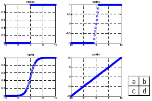
4. Transfer function gives a threshold value to activate neuron. Some of
[image:22.595.198.444.236.400.2]transfer functions are illustrated on Fig.2.1.
Figure 2.1:Some graphics of transfer function
2.3 Recognition
To recognize the plate, Artificial Neural Network (ANN) is used. ANN is
designed to recognize 26 characters of letter and 10 characters of number. Two ANN
topology are designed to recognize letter and number. The designed ANN is a back
prop network (supervised learning), which is able to recognize input matrix in size
1326 x n. Designing of ANN is conducted by applying function newff. ANN has
three layers consisting of input layer, hidden layer and output layer. For ANN‟s
number, there will be 10 neurons for hidden layer and output layer. For ANN‟s letter,
6
Target for the ANN are 26 elements for ANN‟s letter and 10 elements for ANN‟s number. The value of element of each targets are all zero except one element
on specific position which represent the number or letter. For example, the first element is 1 in letter‟s target, represent A. Learning process applied in this network,
is using function traingdx with epoch = 3000, MSE = 1 x 10⁻⁵, and learning rate =
0.05.
Output from the network will be two dimensional matrixes with size 26x n
and 10 x n for ANN‟s letter and ANN‟s number, respectively. The value of output
will be in range 0 and 1. To be recognize, output should be processed first by
converted the highest value to be 1 and other will be 0. Then, the location of element
which has value 1 will be founded and the result will represent number or letter. For
example, output from ANN‟s letter which has value 1 at first element will represent
the letter A, [2].
2.4 Preprocessing/Image Extraction
During this process we scan the handwritten or printed character from a sheet
of paper with the help of a scanning device into graphic/image file format (BMP). As
Mr.Danish Nadeem and Miss Salena Rizvi [4], mentioned, the computer images are
made up of pixels, which have a specific color associated with each of them. This is
identified by the pixel‟s value. These pixels are arranged in the form of a matrix of
horizontal rows and columns. Once the image file is scanned, the information about
the number of rows and columns in the image, pixel offset, and size of image are
contained there in collectively called as the image header. When we are dealing with
a 24-bit bitmap the header is stored in the first 54 bytes as explained in the header
file (bmp.h).
Each image format stores the pixels and their positions in a specific manner.
The 24-bit bitmap uses 3 bytes to store the color (pixel value) associated with each
pixel. In BMP files the preprocessing starts from bottom to the top, hence, the color
of each pixel is stored starting from the bottom and moving right hand upwards.
7
decimal equivalent values are stored in a matrix at the corresponding row column
position. The size of this matrix is equal to the (number of rows * no. of columns (of
[image:24.595.246.390.133.258.2]the image)).
Figure 2.2: Extraction of a character in a matrix
The extraction of the image “E” into a corresponding matrix is shown above.
Here w= Numerical value corresponding to white and b= Numerical value
corresponding to black. From this matrix we find the element which occur the most.
This will correspond to the most prominent color, and hence the background in our
case. This is very obvious as the character will be less prominent than the
background of the paper on which it has been written or printed. Therefore the
number of pixels constituting the background will be less than the number of pixels
that make up the character. Hence our assumption is that the numerical values other
than the background constitute the character
[image:24.595.247.389.515.632.2]