UNIVERSITI TEKNIKAL MALAYSIA MELAKA
(UTeM)
Programming and Simulation of an Arc
Welding Robot
Report submitted in accordance with the partial requirements of the Universiti Teknikal Malaysia Melaka for the Bachelor of Manufacturing Engineering
(Robotics & Automation) with Honours.
By
Lau Ong Yee
UTeM Library (Pind.1/2007)
UNIVERSITI TEKNIKAL MALAYSIA MELAKA UNIVERSITI TEKNIKAL MALAYSIA MELAKAUNIVERSITI TEKNIKAL MALAYSIA MELAKA UNIVERSITI TEKNIKAL MALAYSIA MELAKA
BORANG PENGESAHAN STATUS LAPORAN PSM
JUDUL:
Programming And Simulation of An Arc Welding Robot
SESI PENGAJIAN:
Semester 2 2007/2008
Saya LAU ONG YEE ,
mengaku membenarkan laporan PSM / tesis (Sarjana/Doktor Falsafah) ini disimpan di Perpustakaan Universiti Teknikal Malaysia Melaka (UTeM) dengan syarat-syarat kegunaan seperti berikut:
1. Laporan PSM / tesis adalah hak milik Universiti Teknikal Malaysia Melaka dan
penulis.
2. Perpustakaan Universiti Teknikal Malaysia Melaka dibenarkan membuat salinan
untuk tujuan pengajian sahaja dengan izin penulis.
3. Perpustakaan dibenarkan membuat salinan laporan PSM / tesis ini sebagai bahan
pertukaran antara institusi pengajian tinggi.
4. *Sila tandakan (√)
SULIT
TERHAD
√ TIDAK TERHAD
(Mengandungi maklumat yang berdarjah keselamatan atau kepentingan Malaysia yang termaktub di dalam AKTA RAHSIA RASMI 1972)
(Mengandungi maklumat TERHAD yang telah ditentukan oleh organisasi/badan di mana penyelidikan dijalankan)
(TANDATANGAN PENULIS) Alamat Tetap: P.O.BOX 435, 96100 SARIKEI, SARAWAK
2 May 2008
Tarikh: _______________________
(TANDATANGAN PENYELIA) Cop Rasmi:
Tarikh: _______________________
ii
DECLARATION
I hereby declare that this report entitled “Programming and Simulation of an Arc Welding Robot” is the result of my own research except as cited in the references.
Signature : ………. Author’s Name : Lau Ong Yee
iii
APPROVAL
This report is submitted to the Faculty of Manufacturing Engineering of UTeM as a partial fulfillment of the requirements for the degree of Bachelor of Manufacturing Engineering (Robotic and Automation). The members of the supervisory committee
are as follow:
iv
ABSTRACT
v
ABSTRAK
vi
DEDICATION
vii
ACKNOWLEDGEMENTS
viii
TABLE OF CONTENTS
Declaration ii
Approval iii
Abstract iv
Abstrak v
Dedication vi
Acknowledgements vii
Table of Contents viii
List of Figures xiii
List of Tables xvi
List of Abbreviations, Symbols, Specialized Nomenclature xvii
1. INTRODUCTION 1
1.1 Background of project 1
1.2 Problem Statements 2
1.3 Objectives 3
1.4 Scope of study 3
2. LITERATURE REVIEW 4
2.1 Introduction 4
2.2 Robot Technology Fundamental 5
2.2.1 Classifications of Robots 5
2.2.2 Cylindrical robot 7
2.2.3 Spherical Robot 8
2.2.4 Scara Robot 9
ix
2.2.6 Parallel Robot 11
2.3 Robot End Effectors 12
2.4 Robot Anatomy 13
2.4.1 Mechanical linkage 13
2.4.2 Actuators 13
2.4.3 Sensors 14
2.4.4 Controller 14
2.4.5 User Interface 15
2.4.6 Power Conversion Units 15
2.5 Robot Control Systems 15
2.5.1 Limited Sequence Control 16
2.5.2 Playback With Point-to-Point Control 16 2.5.3 Playback with Continuous Path Control 17
2.5.4 Intelligent control 18
2.6 Simulation And Offline Programming 18
2.6.1 WORK SPACE v5 19
2.6.2 FANUC Robo Guide v2.3.1 20
2.7 Robot Modeling Analysis 20
2.7.1 Forward kinematics 20
2.7.1.1 Homogeneous Transformations 23
2.7.1.2 D-H transformation Matrices 26
2.7.1.3 Forward Kinematics Solutions 27
2.7.1.4 Denevit-Hartenberg Algorithm 28
2.7.2 Inverse Kinematics 28
2.8 Trajectory Planning 31
2.9 Arc Welding 33
2.9.1 Basic Welding Circuit 33
2.9.1.1 Gas Tungsten Arc Welding (GTAW) 33 2.9.1.2 Gas Metal Arc Welding (GMAW) 34 2.10 Considerations of Using Welding Robot 35
2.11Technology of Welding Robot 37
x
3. METHODOLOGY 41
3.1 Introduction 41
3.2 Information resources 48
3.2.1 Book 48
3.2.2 Journal 48
3.2.3 Internet 48
3.2.4 Software 49
3.3 Data Collection /Case Study 49
3.4 Choosing Of Robot and Tools 49
3.5 Programming 50
3.6 Manipulator Kinematics Analysis 50
3.7 Simulation 50
3.8 Conclusion 51
4. DESIGN 52
4.1 Introduction 52
4.2 Workstation Design Consideration 53
4.3 Muffler 54
4.4 Work Station Design 56
4.5 Robot Arc Welding Operation 64
4.6 Conclusion 67
5. RESULT AND ANALYSIS 68
5.1 Introduction 68
5.2 Analysis 68
5.2.1 Forward Kinematics For Welding Robot 69 5.2.2 Forward Kinematics For Positioner Robot 73
xi
5.4 Simulation 81
5.5 Programming 90
5.5.1 Arc Weld Torch Class Module 90
5.5.2 Gripper Behavior Class Module 92
6. DISCUSSION 94
6.1 Introduction 94
6.2 Forward Kinematics 94
6.3 Path Planning 96
6.4 Work cell Arrangement 97
6.5 Arc Welding Process 99
7. CONCLUSION 103
7.1 Conclusion 103
7.2 Further Work And Recommendation 104
REFERENCES 105
APPENDICES
A Gantt Chart for PSM I B Gantt Chart for PSM II C Top View for Welding Station D Close View for Welding Robot E Close View for Positioner Robot
xii
H Technical Specification Manual for Welding Deoxidized Copper and Low Allow Steel
I Module use to move the part
J Module use to reset the position of the part
xiii
LIST OF FIGURES
Page 2.1 Principle, kinematics structure and workspace for Cartesian
robot.
6
2.2 Principle, kinematics structure and workspace for cylindrical robot
7 2.3 Principle, kinematics structure and workspace for spherical robot 8
2.4 Principle, kinematics structure and workspace for SCARA robot. 9
2.5 Principle, kinematics structure and workspace for articulated robot
10
2.6 Principle, kinematics structure and workspace for parallel robot 11 2.7 Hierarchical control structure of a robot microcomputer
controller.
16
2.8 Roll- the rotation of the frame xyz about the z axis 21
2.9 Pitch- the rotation about the y axis 22
2.10 Yaw- the rotation about the x axis 23
2.11 A transformation including both rotation and translation 24
2.12 The trajectory planning problem 31
2.13 Welding robot system design 37
2.14 Weld pool width control system 39
3.1 Flow Chart Show the Project Selection 43
3.2 Flow Chart Show the Methodology of the Project 45 3.3 Flow Chart Show the Methodology Of workstation design 47
xiv
4.2 Workstation for Welding robot 57
4.3 Welding Robot 58
4.4 Positioner robot 58
4.5 work piece-muffler 59
4.6 Weld Joint B 59
4.7 weld joint C 60
4.8 Part A 60
4.9 Jig for part A 61
4.10 Part B 61
4.11 Jig for part B 62
4.12 Part C 62
4.13 Jig for part C 63
4.14 Conveyor 63
4.15 Process Flow for a robotic welding system 66
5.1 Graph distance versus time 80
5.2 Graph speed versus time 80
5.3 Graph acceleration versus time 81
5.4 Both conveyer A and B will move and stop at front of the welding robot and positioner robot
82
5.5 Welding robot will move close to the welding joint to prepare for welding and positioner robot will go and grasp the Part C
82
5.6 Part C been grasped by positioner robot and allocated to weld joint
83
5.7 Positioner robot allocates Part C to the weld joint C coordinate and welding robot will start on welding first half circle.
xv
5.8 Welding robot finish welding first half circle and retract the robot arm, at the same time positioner robot will un-grasp the Part C and move to Part B.
84
5.9 Welding robot start welding second half circle, meanwhile positioner robot will move and grasp Part B at the same time.
84
5.10 Positioner robot allocating Part B at weld joint B coordinate. 85 5.11 Welding robot finish welding weld joint C and retract the robot
arm to home position.
85
5.12 Welding robot move to weld joint B and start welding first half circle.
86
5.13 Welding robot finish weld first half circle and positioner robot will un-grasp Part B and back to home position.
86
5.14 Welding robot start welding at second half circle 87 5.15 Welding robot finish weld second half circle and move back to
home position and Conveyor A and B continue moving to next part.
87
5.13 Welding robot working envelop 89
5.14 Positioner Robot Working envelop 89
5.15 Class Module for Arc Weld torch 91
5.16 Class module for gripper behaviors 93
6.1 Work cell arrangement 98
6.2 Butt Joint 100
6.3 Fillet joint 100
6.4 Torch Angle 101
xvi
LIST OF TABLES
Page
5.1 Arm Parameter for Welding Robot 69
5.2 Arm Parameter for Positioner 73
xvii
LIST OF ABBREVIATIONS, SYMBOLS, SPECIALIZED
NOMENCLATURE
AC - Alternating Current
ACIS - Acquisition and Competitor Intelligence System CAD - Computer-aided design
CCD - Charge-Coupled Device DC - Direct current
DH - Denavit-Hartenberg DOF - Degree of Freedom GMAW - Gas Metal Arc Welding GTAW - Gas Tungsten Arc Welding GUI - Graphical User Interface MIG - Metal Inert Gas
SCARA- Selective Compliant Assembly Robot Arm SMAW - Shield Metal Arc Welding
TIG - Tungsten Inert Gas
1
CHAPTER 1
INTRODUCTION
1.1 Background of project
To increase the productivity of the industry especially in automation sector, automated
process is very important. Automated process at here can be such as screwing,
assembling and welding. The automate process can be refer to the using of automatic
machine or robot arm.
Welding is a type of the process which uses to joint the 2 or more different metals
together permanently with certain strength. During the welding process, hazard gas was
exposed as a shield to protect the work piece from air. This gas will be very hazard, so
automation welding systems are needed in the industrial in condition to protect the
human health.
To ease the work, arc welding robot has been designed. The arc welding robot that had
design should be user friendly, so less cost are used to operate it. Beside that, accuracy
of the robot is important also then more strengthen weld can be made on the position
2
More over, the arc welding robot that had chosen is also must be slim and small in size.
The kinematics require for the arc welding tools are not high if compare to the other
function robot arm such as material handling because less load are applied on it. Slim
arm robot needed at here so the movement of the arc welding robot arm are easy and can
weld the small space availability workspace.
1.2 Problem Statements
Since, welding is an important process that use to joint 2 different metal plates together.
Those welding process are very important especially in the automobile industrial where
they cant just screw the part which want to be joint because strength that given by the
welding are better then screw. In this project focus was been put at the arc welding
process where its more commonly use by the industrial.
The problem that may face now is manual or human welding can not reach to the narrow
space welded part. To overcome the problem, a suitable size arc welding robot arm
should be design and used in industrial.
Beside the narrow space available area, arc welding robot also need to welding the high
position welding part where hard for the human to get reach it without using any
equipment.
To design the arc welding robot, it is needed to consider about the working space,
situation, environment, and also the work piece that want to be weld. All of this factor
can affect the movement and the quality of weld. Before choose the robot to attach the
3
1.3 Objectives
To program and design the arc welding robot that need to put in the industrial,
understanding and familiar with the robot simulation program are important. It can only
do using the simulation software because it saves the cost compare to design a real life
robot. Objective of having this project are:
i. To design a robot to carry out arc welding operation
ii. To design a suitable arc welding work cell.
iii. To simulate the robotic arc welding operation.
1.4 Scope of study
To ensure the objective was successfully achieved, there are several elements that
needed to follow as well.
i. The study used muffler as a product for welding simulation
4
CHAPTER 2
LITERATURE REVIEW
2.1 Introduction
To do the research and analysis of the arc welding robot, it is very important to understand and study all the info that related to the arc welding robot such as fundamental, design requirement and also latest development of the arc welding robot at industrial. At this chapter study of all the important information that required will be carried on.
To do the study and research, most of the sources that obtained are from journal and article that found at the internet and summary of the journal and article will be make and noted down. Beside that, research base on some references book that borrowed from the library will be made also and it can make the report become more compact with all the useful information, knowledge and analysis of the industrial robot or more to the arc welding robot
2.1.1 History of Robot
5
The robot age has begun with the demonstration of the first manipulator with play-back memory by George Devol in 1954. At that time, robot only could exhibit repeatable “point to point” motions. 2 year later, George Devol and Joseph F. Engelberger form a company named Unimation to produce robot based on Devol’s original patents. Unimation robots are also called programmable transfer machines because the main use of the robot is to transfer object from 1 point to another point. Robot at that time is run by hydraulic actuator and has accuracy within 1/10000 inch. At late 1970’s, several by Japanese company conglomerates also had began producing the similar industrial robot as Unimation. (Kumar, 2001)
The first 6-sxis articulated robot are called Stamford arm and invented by Victor Scheinman at Stanford University. This 6-axis robot allowed it to accurately follow the arbitrary paths in space and widened the potential use of the robot to more sophisticated applications such as assembly and arc welding. Second robot arm called MIT arm also been designed by Scheinman after receiving a fellowship from Unimation to develop his design. (Kumar, 2001).
2.2 Robot Technology Fundamental
Study and understanding of the robot technology is important in this research where it needed in determine the component of workstation and work piece.
2.2.1 Classifications of Robots
6
Each type of the industrial robot will have it own function and differences with others type. Now, there are 6 common type of the industrial robot that can get from the industrial robot manufacturer which will state at next session.
2.2.1.1Cartesian Robot/Gantry Robot
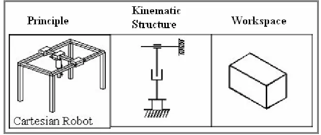
Cartesian robot is robot whose arm has three prismatic joints and axes are coincident with a Cartesian coordinates.(Man, 2005) Refer to Figure 2.1 for kinematics structure and workspace of the Cartesian robot. Advantages that can be seeing on this Cartesian robot are they are capable of moving in multi linear direction. Beside that, this kind of robot also can do straight line insertion and easy to program. Since the axes of the Cartesian robot are supported at the both end, so it become most rigid robotics structure among the others. Because of it rigid structure, so it is very suitable for pick and place application, machine tools loading and part assembly which application that required to manipulate at high load.
[image:24.595.152.483.521.660.2]Anyway, there is also having some disadvantages of using Cartesian robot. The main disadvantages of this robot are it requires a large volume of space to operate in, though the whole space is not used.
Figure 2.1: Principle, kinematics structure and workspace for Cartesian robot.