Reduced-Order Modelling of Vortex-Induced Vibration of
Catenary Riser
Narakorn Srinila, b *, Marian Wiercigrocha, Patrick O’Brienb a
Centre for Applied Dynamics Research, School of Engineering, University of Aberdeen, King’s College, Scotland UK, bMCS, Aberdeen, Scotland UK
Abstract
A new reduced-order model capable of analyzing the vortex-induced vibration of catenary riser in the ocean current has been developed. This semi analytical-numerical approach is versatile and allows for a significant reduction in computational effort for the analysis of fluid-riser interactions. The incoming current flow is assumed to be steady, uniform, unidirectional and perpendicular to the riser plane of initial equilibrium curvature. The equations of riser 3-D motion are based on a pinned-pinned, tensioned-beam or flexural cable, modelling which accounts for overall effects of riser bending, extensibility, sag, inclination and structural nonlinearities. The unsteady hydrodynamic forces associated with cross-flow and in-line vibrations are modelled as distributed van der Pol wake oscillators. This hydrodynamic model has been modified in order to capture the effect of varying initial curvature of the inclined flexible cylinder and to describe the space-time fluctuation of lift and drag forces. Depending on the vortex-excited in-plane/out-of-plane modes and system fluid-structure parameters, the parametric studies are carried out to determine the maximum response amplitudes of catenary risers, along with the occurrence of uni-modal lock-in phenomenon. The obtained results highlight the effect of initial curvatures on the nonlinear dynamics of riser undergoing vortex-induced vibration.
Key Words: Reduced-Order Modelling, Vortex-Induced Vibration, Catenary Riser, Wake Oscillator, Fluid-Structure Interaction
* Corresponding Author: [email protected] Main text
1. INTRODUCTION
Steel catenary risers (SCRs) are widely used in offshore installation, exploration and production. Because of their promising technological and commercial solutions, SCRs have become primary candidates for future ultra deepwater oil & gas industry. One of the key issues in the analysis and design of SCRs in the ocean current is to estimate and control the fatigue damage due to vortex-induced vibration (VIV). Nevertheless, recent understanding of VIV is still based on empirical and/or simplified linearized models of straight top-tensioned risers (TTRs). Due to the impracticality of time-consuming 3-D flow visualizations by CFD (Computational Fluid Dynamics) for a long slender structure, the VIV fluid excitation and damping forces usually rely on the hydrodynamics data obtained from a laboratory testing of an elastically-supported rigid cylinder vibrating with 1 or 2 degree-of- freedom (DOF) in a uniform flow at low Reynolds (Re) numbers. Therefore, many uncertainties arise when designing the SCRs which are actually flexible inclined cylinders having initial sags and varying curvatures. As a matter of fact, SCRs are substantially different from TTRs, e.g., in view of the current flow direction relative to the pipe axis. The incident angle is arbitrary and different from 90o when the flow aligns with the SCR plane of curvature. Moreover, a slender long sagged structure exhibits the cable-dominated behavior and has multiple natural frequencies which, in turn, potentially give rise to different in-plane/out-of-plane modal interactions occurring in cross-flow/in-line VIV.
of experimental observations could not be theoretically explained. Lie et al. (2001) pointed out the significance of using the time domain approach with the inclusion of structural nonlinearities
in the VIV analysis of SCRs.
Recently, an investigation into vortex shedding patterns and fundamental wake topology when
the flow past a stationary curved circular cylinder has been carried out by Miliou et al. (2003, 2007). As a result of pipe curvatures, the computational simulations highlight different kinds of
wake characteristics depending on the pipe (convex or concave) configuration and its orientation
with respect to (aligned with or normal to) the incoming flow. When the flow is uniform and
normal to the curvature plane, the cross-flow wake dynamics of curved pipes behave qualitatively
similar to those of straight pipes. This is in contrast to the case of flow being aligned with the
curvature plane where wake dynamics change dramatically. For this reason, in our initial study,
the current flow approaching the SCR is assumed to be steady, unidirectional, uniform and
perpendicular to the curvature plane of inclined cylinder (see Fig. 1). This avoids the multiplicity
of vortex shedding frequencies (e.g., the case of flow aligned with the curvature plane) which
would complicate the modelling and analysis.
Herein, the main emphasis is kept to evaluate the cross-flow and in-line VIV of SCRs due to
fluctuating lift and drag forces, respectively. The paper is structured as follows. In Section 2, a
general realistic fluid-structure interaction model for SCR (as well as TTR) with arbitrary sag and
inclination is developed. The geometrically nonlinear equations of riser 3-D motion are derived
accounting for both bending and tension rigidities. The catenary riser static configuration and
corresponding modal shape functions are approximated by the hyperbolic and sine-series
continuous functions, respectively. To model complex hydrodynamics where dynamic fluid
forces are spatially distributed on the underwater cylindrical body, a phenomenological approach
is used where spatially wake oscillators with relevant empirical coefficients are implemented. By
coupling the wake oscillators to the riser equations governing in-plane and out-of-plane motions,
a reduced-order model for the analysis of hydro/elastic-cylinder interaction due to uni-modal VIV
is obtained in Section 3 and then systematically investigated in Section 4. The main objectives are
(i) to determine the occurrence of lock-in phenomenon when varying the reduced flow velocity
parameter and to predict, as well as validate, the associated maximum response amplitudes of
SCRs, (ii) to investigate the effect of overall fluid-structure parameters and (iii) to highlight the
2. FLUID-RISER INTERACTION MODEL
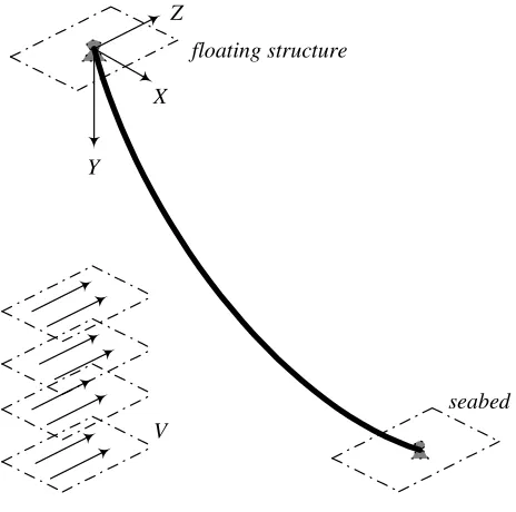
With reference to the global Cartesian coordinate system, Figure 1 depicts a general 3-D
continuum model of SCR connected from a stationary floating structure to a seabed with simply
pinned-pinned supports. A horizontal offset XH and water depth YH define a chord inclination angle of riser (i.e., r = tan-1YH/XH). Riser properties are considered to be spatially uniform with mass/length (m), viscous damping coefficient (c), hydrodynamic diameter (D), effective bending
(EI) and axial (EAr) stiffness. The steady incoming uniform flow, having density () and normal
velocity (V), is in the Z+-direction perpendicular to the SCR plane (XY) of initial equilibrium curvatures. Following the Strouhal number (St) law of a stationary cylinder, the flow entails a
single natural frequency (rad/s) of vortex shedding in the wake (s), i.e., s= 2StV/D, where St ≈ 0.2 being assumed for a sub-critical flow condition with 300 < Re < 3x10⁵ (e.g., Sumer and Fredsoe 1997).
2.1 Geometrically Nonlinear Equations of Riser Motion
In deepwater applications, the riser has a large aspect (length-to-diameter) ratio and is usually
predominated by the tension behavior. Therefore, by considering the riser as a flexural sagged
cable-like elastic structure satisfying the Euler-Bernoulli beam hypothesis, the nonlinear
partial-differential equations of riser motion about its planar (XY) static equilibrium configuration may be
expressed in a general dimensional form as (Srinil et al. 2007; Ricciardi and Saitta 2008)
222 2 2 2 2
1 2 2 1 , 2 a r
u u u x u y v
m m c T EA
t t s s s s s s
u v w x u x u
EI F
s s s s s s s s
(1)
222 2 2 2 2
2 2 2 1 , 2 a r
v v v x u y v
m m c T EA
t t s s s s s s
u v w y v y v
EI F
s s s s s s s s
(2)
222 2 2 2
3 2 1 , 2 a r
w w w x u y v
m m c T EA
t t s s s s s s
u v w w w
EI F
s s s s s s
(3)
represent global dynamic (static) displacement in the horizontal (X), vertical (Y) and transversal or out-of-plane (Z) direction, respectively. T denotes axial static tension of riser due to effective weight, madenotes potential added mass (CAAr, where Aris circular cross-sectional area, CA=1), and Fi denotes external hydrodynamic (lift/drag) forces leading to VIV. By accounting for both bending (Ricciardi and Saitta, 2008) and axial (e.g., Srinil et al. 2007) rigidities, Equations (1)-(3) are also valid for a top-tensioned riser (TTR), mooring line or horizontal pipeline with zero sag. Overall inertia effects and structural nonlinearities (Srinil and Rega, 2007b), which are meaningful in the case of large dynamic displacement or deformation, are fully accounted for. It is worth mentioning that the effects of shear, torsion, seabed interaction and internal-flow-induced friction forces, which are quite important for SCRs, are not herein considered. In the following, all the space-related variables and associated equations are non-dimensionalized with respect to D.
For convenience in our analytical modelling, a planar submerged static configuration of SCR solely due to effective self weight is assumed, whereas the bending restraint and the uniform current flow play a role after the performance of static equilibrium. The neglected static bending is plausible because the end boundaries are pinned-pinned and the SCR curvatures are relatively small. Accordingly, the higher-order spatial derivatives of x and y in Eqs. (1) and (2) are disregarded, and the static profile of SCR is simply governed by
2
1 ,
H
E T
y W y
D (4)
in which a dash denotes differentiation with respect to the new space variable x, WE is the computed effective weight accounting for buoyancy effect, and TH is a horizontal component of riser tension which is spatially constant. By directly integrating Eq. (4) twice, the exact hyperbolic function-based formula describing the catenary configuration reads
1 2
( ) H cosh E ,
E H
T W D
y x x C C
W D T
(5)
where C1are C2 can be determined based on boundary conditions. Thus, for a given D, m, r, XH and TH, the SCR equilibrium can be explicitly determined and then substituted into Eqs. (1)-(3) as an embedded continuous function.
2 1
1
sin sin ,
2
L L
F F C DV (6)
2 2
1
cos cos ,
2
L L
F F C DV (7)
2 3
1
, 2
D D
F F C DV (8)
where is a local angle of inclination (measured clockwise from the X-axis in Fig. 1) based on Eq. (5), in which ≈ tan-1(y). CL(s,t) and CD (s,t) are unsteady lift and drag coefficients per unit
length, respectively. It is worth noting that the mean drag, and possibly also the mean lift (Miliou
et al. 2003, 2007), component, which potentially gives rise to a new SCR equilibrium, is here omitted as we focus on the fluctuating component.
2.2 Nonlinear Wake Oscillators
Biolley FLB (2004) in order to overcome some limitations of previous wake oscillators. Both
models capture the self-limiting amplitude responses at zero structural damping and reproduce
some qualitative, as well as quantitative, aspects of VIV when compared with experiment results.
Regarding the application to flexible cylinders, the SB model has been used in the analysis of
single-mode cross-flow/in-line VIV of horizontally suspended cables by Kim and Perkins (2002).
The FLB model has been considered by Violette et al. (2007) for the cross-flow VIV of long
straight tensioned-beam and cable based on a linear structural model. They showed a good
comparison with direct numerical simulations and experiments.
In this study, the SB model is considered. The distributed lift coefficient CL (s,t) and associated
wake oscillator Q (s,t) are originally expressed as
L
,
, 2 N
, ,s
C s t Q s t Y s t
(9)
2 2
2
0
, s L 4 , , s , s N , ,
Q s t G C Q s t Q s t Q s t FY s t (10)
where is a so-called stall parameter (Triantafyllou et al. 1994), YN is defined as a local riser
displacement normal to its tangential axis, CL0 is a given lift coefficient of a stationary cylinder, and a dot denotes differentiation with respect to time. Wake coefficients are F and G, with the
overbar denoting “empirical” quantity. To account for the effect of SCR initial curvature and also
describe the concurrent horizontal/vertical displacement components of SCR in-plane motion, we
project QX = -Qsin and QY = Qcosby using the cosine law. This entails two new wake
oscillators
2 2 2
0
3 4
,
sin sin sin sin sin
s L X s X X s X s
X GC Q GQ Q Q Fu
Q
2 2 2
0
3 4
.
cos cos cos cos cos
s L Y s Y Y s Y s
Y GC Q GQ Q Q Fv
Q
(12)
In contrast to Eq. (10), Eqs. (11) and (12) are now dependent on both time and space variables.
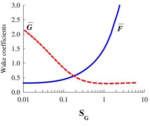
QXand QYare to be determined together with uand v. The wake coefficients (F,G) are obtained
by matching a series of experimental data which generally include the measurement of maximum
response amplitude of cylinder A/D and vortex-to-structural frequency ratio during VIV (Skop
and Balasubramanian 1997). As exemplified in Fig. 2, F and G are dependent on the system
2
2 2 .
8 St a
D
m m
(13)
As for in-line VIV, very few theoretical studies have proposed a wake oscillator governing the
drag coefficient, and a practical tool for predicting the in-line VIV is still unavailable in industry.
However, it is well known from many experiments (e.g., Okajima et al. 2004) that in-line VIV
may take place in a reduced velocity range lower than that of cross-flow VIV with
symmetric/alternate vortices. In addition, it may take place in the same reduced velocity range as
cross-flow VIV with alternate vortices. Typically, the in-line VIV has a frequency twice that of
cross-flow VIV during a complete 2-D lock-in. This entails that both out-of-plane and in-plane
modes, whose natural frequencies are in nearly-tuned 2:1 ratio, are simultaneously excited. Based
on this evidence and also considering the practical case of alternate vortices, we assume, by
following Currie and Turnbull (1987), Kim and Perkins (2002),
,
, 1
, 2
, , 2D
s s
C s t P s t P s t w s t
(14)
2 2
2
0, 2 s D 4 , , 4 s , 2 s , ,
P s t H C P s t P s t P s t Jw s t (15)
where Pis the in-line wake component, H and J are empirical coefficients, and CD0is the drag
coefficient of the stationary cylinder.
It is worth emphasizing that Eqs.(6) and (11) (7 and 12) are dependent on both QX and u (QY
and v), exhibiting the two-way feedback coupled system of the wake-riser interactions. This holds
also for Eqs.(8) and (15) involving Pand w. In place of Eqs. (11) and (12), Eq. (10) is considered
for cross-flow VIV of a straight vertical riser or horizontal pipe.
2.3 Riser Natural Frequencies and Modes with Bending-Tension Effect
In the framework of analytical modelling, the natural frequencies and mode shapes of
pinned-pinned SCRs (as well as TTRs) have to be determined in terms of continuous functions. In so
doing, the linear equations of undamped free in-plane (u, v) and out-of-plane (w) motion,
corresponding to Eqs.(1)-(3), are considered and given in a dimensionless form by
2 2
3 3 3
1
1 y 0,
u b u c u v
2
2 2
3 3 3
1
1 0,
y y
v b v c u v
(17)
2 2
3 1
0,
w b w c w
(18)
where =(1+y2)1/2, =EAr/TH, b2=EI/(m+ma)D4, c2 = TH/(m+ma)D2. With zero displacements and
bending moments at the end boundaries, the in-plane and out-of-plane modes are postulated in
terms of a Fourier sine-based series as
1
, sin ,
N
J J
n
n H
n xD
U x t t
X
(19)where, for J= 1-3, U1= u, U2= v, U3= w, J n
are generalized time coordinates, N is the number
of retained sine functions. By substituting Eq. (19) into Eqs. (16)-(18) and applying the Galerkin
method, the eigenvalue problem is solved via a hybrid analytical-numerical solution proposed by
Srinil et al. (2007). Note also that, for a pinned-pinned TTR with uniform tension and bending,
both frequencies and modal shapes can be alternatively obtained via closed-form formulae, with
both kth in-plane/out-of-plane modes being similar to taut-string modes. Nevertheless, this is not
the case for SCRs, whose in-plane modes are significantly dependent on initial sagged and curved
configurations. These modes are indeed neither purely symmetric nor anti-symmetric due to the
effect of geometric asymmetry.
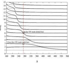
To understand the global in-plane/out-of-plane frequency relationships when varying some key
parameters of the riser, it is worth constructing a spectrum of natural frequencies in still water.
This is useful in view of detecting the potential cross-flow/in-line VIV modes. Due to the
combined effect of riser bending, extensibility (axial tension) and geometry (sag/inclination), a
single dimensionless tensioned-beam parameter is introduced, namely
, a L T EI
(20)
where L is the riser equilibrium length and Ta is the tension at maximum sag of SCR (or the
averaged tension in the case of TTR). This parameter describes how the flexural (small ) or axial
(large ) rigidity plays a predominant role. By normalizing the obtained SCR frequencies (by
the lowest frequency of the corresponding TTR (T, the natural frequency spectrum of
tension-dominated risers is illustrated in Fig. 3 with Tvs. and solid (dotted) lines denoting in-plane
In Fig. 3, Ta(also L) is varied while keeping EIfixed. > 560 represents the case of TTRs (as
sag 0, giving rise to the negligible WE effect with respect to Ta). The k in-plane/out-of-plane
frequency ratio is apparently equal to 1 (like taut-string frequencies). However, when decreasing
Ta(increasing sag), the lower (< 560) reflects the case of SCRs whose kin-plane/out-of-plane
frequency ratio is different from 1. In some circumstances, the vortex frequency s(for a given
V) may simultaneously excite the in-line/cross-flow VIV modes having a 2:1 frequency ratio, as
exemplified by the circles corresponding to the 6th out-of-plane/2nd in-plane modes for ≈ 272
(vertical dashed line). With a further increase of V (thus s) for such , it is also possible that two
higher in-plane (5th and 6th) modes – whose frequencies are nearly equal at a so-called avoidance
region (Srinil and Rega, 2007a) – can be both excited. This may result in a multi-mode lock-in of
cross-flow VIV (Hover et al. 1997). Yet, our attention is focused on the uni-modal lock-in
behavior which will be analyzed through a reduced-order model derived in the following section.
3. REDUCED-ORDER MODEL FOR CROSS-FLOW AND IN-LINE VIV
With the aim of minimizing the computational effort, a reduced-order model describing the
hydrodynamics-elastic cylinder interaction is now developed. The first-order (i.e. state-space)
differential forms of Eqs. (1)-(3), (11), (12) and (15) are considered, and the expansion of
displacement and velocity (defined by Ai, Bi) variables is postulated by the following forms,
For riser dynamics:
1 1 1 1 2 2 1 1 3 3 1 1 , , , , , .
m m m m
m m
m m m m
m m
n n n n
n n
u A u f A p
v A v f A p
w A w h A q
(21)For wake dynamics:
1 1 1 1 2 2 1 1 3 3 1 1 , , , , , .
x x m m m m
m m
y y m m m m
m m
n n n n
n n
Q B Q d B e
Q B Q d B e
P B P z B o
(22)where m and m represent the horizontal and vertical component of mth in-plane (cross-flow
VIV) modal shape function, nrepresents the nthout-of-plane (in-line VIV) modal shape function,
fm(dm), pm(em), hn(zn), and qn(on) are the corresponding generalized coordinates of riser (wake)
oscillator and the riser dynamically respond in a similar fashion having a spatial shape profile
corresponding to a potentially vortex-induced mode, the number of considered in-plane
(out-of-plane) modes is equal to 1. This assumption is plausible (see, e.g., Skop and Griffin, 1975; Kim
and Perkins, 2002) as the flow is uniform and its direction is perpendicular to the SCR in-plane
curvature, giving rise to a single vortex shedding frequency. Moreover, because the VIV
amplitude is relatively small with respect to D(Sarpkaya 2004), contributions from higher-order
modes through structural nonlinearities may be negligible (Srinil and Rega, 2007b). By
substituting Eqs. (21) and (22) into Eqs. (1)-(3), (11), (12) and (15), applying the Galerkin
method with relevant boundary conditions and orthonormalization of modal shapes, a set of
nonlinearly coupled equations, governing a single in-plane/out-of-plane mode VIV response and
fulfilling the 2-D lock-in (i.e. n ≈ 2m≈ 2s) condition, is obtained as
fm pm, (23)
2 2 2 3 2 2
G
2 S
m m m m m m m m mn n m m mn m n m m
p p f f h f f h d , (24)
n n
h q , (25)
2 2 3 2G
2 S / 2 / 4 / 4,
n n n n n n nm n m nm n m n n n n n n
q q h h f h f h z o (26)
m m
d e , (27)
2 2 2
0
4 m
m m L m m m s m m m
m G
e GC e e d d Fp
, (28)
n n
z o , (29)
2 2 2
0
4
4 n
n n D n n n s n n n
n H
o HC o o z z Jq
, (30)
where the modal shape-based quadratic and cubic nonlinear coefficients are given by
/ 2
3 2 2 3
3 0 3 1 2 H X D
m m m m m m m
c
y y dx
, (31)
/ 2 2 2 3 0 1 2 H X Dmn m n m n
c y dx
, (32)
/ 2
4 2 2 4
3 0 1 2 2 H X D
m m m m m
c
dx
, (33)
/ 2
2 2 2 2 3 0 1 2 H X D
mn m n m n
c
dx
/ 2 4 3 0 1 2 H X D n n c dx
, (35)/ 2 / 4
2 3 4
3
0 0
H H
X D X D
m m
m m dx m dx
y y
, (36)/ /
2 4
0 0
.
H H
X D X D
n ndx ndx
(37)It can be analytically proved that nm 2mn and nm mn. Eqs.(31)-(37) are numerically
integrated based on a 64-point Gaussian Quadrature. When considering a straight riser (or
horizontal cable) involving an anti-symmetric mode in the VIV, some coefficients are trivial due
to the nonlinear orthogonality of modal shape functions (Srinil and Rega 2007a). Depending on
assigned initial conditions, empirical coefficients and fluid-structure parameters, Eqs.(23)-(30)
are simultaneously solved by numerical integrations with a proper time stepping method. To
perform parametric studies, it is worth making a reference to a reduced flow velocity parameter,
2 1 , St r m V U D
(38)
where = m/sbeing a reduced angular frequency of the riser. Here, Dis fixed, whereas Uris
varied through the first or second relationship in Eq. (38). In the first relation, the flow velocity V
is varied whereas, in the second relation, the vortex frequency s or the riser in-plane frequency
mis varied through while keeping V(Re) fixed. Typically, for convenience in the experiments,
V is increased or decreased while keeping other properties of the tested cylinder fixed. Yet, for
long flexible cylinders such as marine risers, the system frequencies (m, n) may be closely
spaced (e.g., Fig. 3) and, when varying such V, different potential modes may be excited
according to the resultant shedding frequency s. Moreover, due to the associated variation of Re,
the assumption of sub-critical flow in making use of the wake oscillator might not be valid when
further increasing V. To circumvent this, the V(Re) may be fixed by parametrically varying mor
s. If mis varied, the so-called true, in-situor oscillation frequency is realized as m ± , where is a cross-flow frequency detuning parameter. This variation is practically reasonable since the
structural natural frequency during VIV is indeed modulated due to the varying added mass
coefficient (Blevin 1990, Vandiver 1993). Alternatively, by keeping mfixed, s may be varied
oscillating cylinder may be different from that of stationary cylinder given by Strouhal law. The
variation of out-of-plane (or in-line VIV) frequency n can be made in the same manner. When
obtaining the steady-state solution of Eqs. (23)-(30), the temporally (fm or hn) and spatially (m, φmor ζn) maximum amplitudes due to cross-flow (Am/D) and in-line (An/D) VIV can be deduced from the time histories in conjunction with Eq. (21). Namely,
2 2
,
.
m m m m m
n n n
A D Max f f
A D Max h
(39)
Because of solving for the temporal generalized coordinate (fmor hn) based on a single-mode VIV analysis, the spatial location of maximum VIV amplitude is the same as the anti-node position of
the corresponding linear mode shape function (m, φmor ζn).
4. PARAMETRIC INVESTIGATIONS
As an example, we first consider a tension-dominated SCR with high aspect ratio (L/D) ≈ 2581,
r = 30o, ≈ 1669, b2 ≈ 8.1x10⁶, c2 ≈ 7.8x10⁴, ≈ 272 (corresponding to Fig. 3). The fluid
-structure parameters are ≈ 0.044, SGm = SGn ≈ 0.068 (i.e. both in-plane/out-of-plane modal
damping values are assumed to be equal, with = 0.003), CL0= 0.28, CD0= 0.20, ≈ 0.183, F≈
0.398 and G≈ 1.061 (see Fig. 2). As analytical formulae for estimating the empirical wake
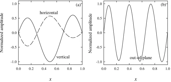
coefficients of in-line VIV are unavailable in literature, we shall assume J FandH G. For the given averaged V = 0.34 m/s, the computed s≈ 1.112 rad/s and the potential cross-flow (in-line) VIV mode corresponds to the 2nd in-plane (6th out-of-plane) mode (Fig. 3) with m≈ 1.033
(n ≈ 2.207) rad/s. The associated normalized in-plane (,) and out-of-plane () modal shape
functions projected onto the X-axis are displayed in Fig. 4 with convergent 40 sine functions (Srinil et al. 2007). These nearly-symmetric (4a) and anti-symmetric (4b) modes, together with above-mentioned parameters, are considered, unless stated otherwise, in the following parametric
studies of uni-modal cross-flow/in-line VIV.
4.1 Nonlinear Dynamic Interactions and Uni-Modal Lock-In Phenomenon
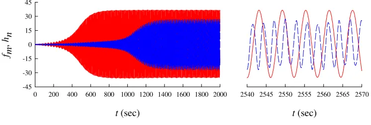
Depending on assigned initial displacement/velocity conditions, the time histories associated with
cross-flow (fm) and in-line (hn) displacement amplitudes are comparatively displayed in Fig. 5 with Ur≈ 6. It can be seen that, after some transient dynamics, the cross-flow VIV response (red line) reaches the steady state or “limit cycle” prior to the in-line VIV response (dashed blue line),
ratios, the phase angle between cross-flow and in-line VIV has recently been evidenced by an
experiment study of elastically-mounted rigid cylinder vibrating with two degrees of freedom
(Jauvtis and Williamson 2004). Overall dynamic responses in Fig.5 are perfectly periodic, with
cross-flow displacement amplitudes being greater than in-line amplitudes (Sarpkaya 2004). In
turn, the corresponding oscillating (in-line:cross-flow) frequencies are nearly tuned in a 2:1 ratio.
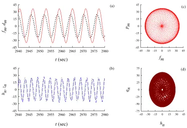
A comparison of displacement responses governing the riser and the fluid wake force is displayed
in Fig. 6a for cross-flow VIV ( fmvs. dm) and in Fig. 6c for in-line VIV (hnvs. zn), along with the
associated phase portraits (fm, pm) and (hn, qn) in Figs. 6b and 6d, respectively. It is shown that a
slight phase difference between wake and riser steady-state responses occurs more apparently in
cross-flow VIV (Fig. 6a). The closed-orbit phase plots (6b and 6d) show the passage from
transient to steady-state motion as well as the periodicity of limit cycle, with the cross-flow
velocity (displacement) parameter pm(fm) having smaller (larger) maximum amplitudes than the
in-line velocity (displacement) parameter qn (hn). Overall, Figs. 6 and 7 show the fundamental
characteristics of uni-modal wake-riser interaction which involves a single-frequency,
self-limiting, and steady-state response.
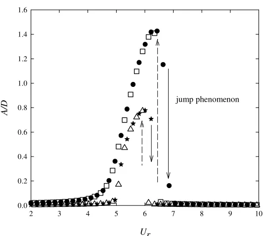
The typical lock-in or synchronization in which cross-flow and in-line VIV occur over a wide
range of the reduced flow velocity Ur is now highlighted, along with the predicted maximum
response amplitudes A/D. As aforesaid through Eq. (38), Urcan be altered by either varying V, s
or m (n), which, in turn, parametrically affects Eqs. (23)-(30). For the sake of comparison, the
results with varying Vand system frequencies are presented in Figs. 7 and 8, respectively. In Fig.
7, the flow velocity is either increased or decreased in the range 0.1 < V < 0.7 m/s (≈ 3.2x10⁴ < Re < 2x10⁵) with a small increment of 0.01 m/s. Both cross-flow and in-line VIV amplitudes are
comparatively plotted versus Ur. It can be seen that a large A/D variation due to cross-flow
(in-line) VIV occurs in the range 4 < Ur < 7 (5 < Ur < 6), with the discontinuity of two response
branches owing to a jump phenomenon or hysteresis effect. This highlights the lock-in
phenomenon whereby the riser and the fluid are in the internally-resonant condition, with the
vortex shedding frequency locking into the riser oscillation frequency (Sumer and Fredsoe 1999).
When increasing or decreasing V, overall riser responses coincide: for the sudden jump-down and
jump-up, critical Ur values are nearly the same. The bent-to-right exhibits a hardening behavior
likely due to the predominant cubic nonlinearities associated with wake oscillators. The greater
response amplitudes – as well as the broader regime of lock-in – correspond to the cross-flow
VIV giving rise to the maximum A/D≈ 1.426, in comparison with maximum A/D ≈ 0.779 due to
in-line VIV. Overall, the presented theoretical wake-riser interaction model provides good
qualitative agreement with theoretical and experimental literature for cross-flow/in-line VIV, in
view of maximum attainable amplitudes (up to A/D ≈ 2 for flexible cylinders) and the uni-modal
lock-in prediction (Blevin 1990, Sarpkaya 2004).
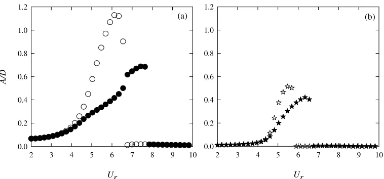
Considering now the fixed flow velocity v = 0.35 m/s and with this assumption the
vortex-excited modes are the same as in Fig. 4. By varying s or m (n) through the corresponding
frequency detuning parameter or within the same range of [-0.6, 1.7], similar response
diagrams exhibiting the lock-in phenomenon are obtained in Figs. 8a (cross-flow VIV) and 8b
(in-line VIV). The in-line vibration response and the associated lock-in bandwidth (Fig. 8b) seem
to be more sensitive to the frequency variation. Yet, overall achievable amplitudes when varying
sor m(n) are comparable, being approximately equal to those predicted in Fig. 7 with varying
V. This similarity of Figs. 7 and 8 may be attributed to that the lock-in occurs in the range about
4<Ur<7 (5<Ur<6 or 8) with 1.3 > m/s > 0.7 (2.2 > n/s > 1.7) for cross-flow (in-line) VIV,
rather than being at m/s=1 (n/s= 2) or Ur= 5 for the stationary riser.
A comparison of VIV responses between SCR and TTR having the same flexural
tensioned-beam parameter ≈ 272 is now shown in Fig. 9 with the case of increasing V. From Fig. 3, the
potentially excited modes for TTR correspond to the 3rd cross-flow (m ≈ 1.095 rad/s) and sixth
in-line (n ≈ 2.194 rad/s) modes, whose shapes are perfectly symmetric and anti-symmetric with
respect to middle span with three and six half-sine waves, respectively. Based on the same given
fluid-structure parameters, empirical coefficients and initial conditions as before, the response
comparison in Fig. 9a highlights that the cross-flow VIV of TTR entails smaller A/D (≈ 1.262) with respect to the cross-flow VIV of SCR (≈ 1.425). This occurs although the lock-in ranges and corresponding response jumps appear similar for both risers. Such predicted amplitude difference
is attributed to the effect of riser geometry, namely the riser initial curvatures, because TTR
(SCR) has zero (non-zero) sag and has one (two) displacement component in the cross-flow VIV.
The cross-flow amplitudes of TTR tend to be comparable to those of straight spring-mounted
cylinders reported in the literature. On the contrary, the in-line VIV amplitudes for both TTR and
SCR in Fig. 9b are nearly comparable (A/D≈ 0.76). This is physically reasonable because the in-line modes of SCR and TTR are the same 6th mode (Fig. 4b) and the in-line VIV of SCR subject
to flow normal to the curvature plane is not significantly affected by riser initial curvatures.
4.2 Influence of System Parameters
responses is highlighted in Fig. 10. A beam-dominant SCR of Moe et al. (2004) is now
considered, whose parameters are L/D≈ 835, r= 37.62o, ≈ 16832, b2≈ 2.35x10⁹, c2 ≈ 1.2x10⁶,
≈ 21, ≈ 0.121, SGm= SGn≈ 0.082, F≈ 0.432 and G≈ 0.982. With the averaged V= 1 m/s (s
≈ 89.76 rad/s), the potentially excited cross-flow and in-line modes are the 10th in-plane (m ≈
82.78 rad/s) and 15th out-of-plane (n ≈ 169.35 rad/s) modes, respectively. This highlights the
VIV at high-mode numbers. By considering either linear (omitted 2 2 3 2 2 3
, , , , , ,
m n m n n m n m n
f h f h h f h f h ) or
nonlinear equations of riser motion (Eqs. 23-26), the associated maximum A/D responses are
comparatively plotted versus Ur in Fig. 10 in the case of increasing V. Overall, the jump
phenomena are observed by both linear/nonlinear models. However, the comparison reveals
noticeable amplitude differences in both cross-flow (Fig. 10a) and in-line (Fig. 10b) VIV, though
based on the same assigned initial conditions. The linear model substantially overestimates the
A/D during the lock-in. The predicted maximum cross-flow (in-line) A/D amplitudes are about
1.13 (0.52) and 0.69 (0.42) by linear and nonlinear models, respectively. Moreover, the linear
model neglects the hardening (bent-to-right) nonlinear effect. This highlights that the geometrical
nonlinearities – which indeed play a crucial role in establishing a new riser equilibrium caused by
mean drag – should be accounted for, at least, for the sake of quantitative correctness.
Next, it is interesting to understand how the vortex-excited modes having different spatial
shapes affect the VIV responses. For the fixed ≈ 272 (the SCR in Fig. 3), the cross-flow and
in-line VIV modes whose frequency values are in 1:2 ratio are the 1st(2nd, 3rd, 4th,…) in-plane and
4th (6th, 8th, 10th,…) out-of-plane modes, respectively. Note that, due to the SCR in-plane
configuration, the spatial shape profiles of odd (1st, 3rd) or even (2nd, 4th) in-plane modes are not
perfectly anti-symmetric or symmetric (e.g., see Fig. 4a), whereas the spatial shape profiles of
even out-of-plane modes are perfectly anti-symmetric (e.g., see Fig. 4b). With the same given
parameters and empirical coefficients, the analysis of lock-in regime is performed in the case of
increasing V, and the maximum A/D results are compared in Table 1 for different
potentially-excited modes. It can be seen that the in-line A/D amplitude tends to slightly change with the
corresponding mode order. This is in contrast to the case of cross-flow VIV, where different
excited in-plane modes entail different maximum A/D, depending on the horizontal/vertical shape
functions affecting overall coefficients in Eqs (31)-(37). Again, such difference between
cross-flow/in-line VIV is due to the influence of initial sag or curvatures of SCR on the in-plane
vibration. The even (2nd, 4th) modes seem to be the most dangerous case for this SCR example.
In practical design, the inclinations and sags of SCRs are variable, depending on the geometry
rigidity). This, in turn, influences the beam-cable behaviour of risers. Herein, to appreciate the
solely effect of riser sag on VIV, we now consider three SCRs having different tensioned-beam
parameters (Fig. 3). For the sake of comparison, the bending stiffness EI, the 2nd in-plane
(cross-flow) and 6th out-of-plane (in-line) modes are fixed in the VIV analysis of each SCR. With
increasing V, the predicted maximum A/Dduring cross-flow and in-line lock-in are comparatively
reported in Table 2. It can be seen that both maximum cross-flow and in-line amplitudes slightly
increase with decreasing or increasing sag-to-span ratio. This is physically reasonable because
the larger sagged SCR is more slender and flexible, potentially leading to larger vortex-induced
displacements.
The mass-damping parameter (e.g., SG) also plays a significant role in the VIV analysis and
prediction (Sarpkaya 2004) because it affects empirical coefficients, vortex-shedding modes
(Williamson and Roshko, 1988) and overall VIV response behaviors. As a matter of fact, many
experimental VIV studies of elastically-mounted rigid or long flexible cylinders subject to normal
flow depend on the measured mass and damping values. Therefore, it is worth making a
comparison of analysis results with a series of experimental data. In Fig. 11, we compare the
predicted maximum amplitudes during lock-in with those gathered by Skop and Balasubramanian
(1997), by reporting 2A/Din the so-called Griffin plot (Williamson and Govardhan, 2004). Three
SGvalues (0.068, 0.227, 1.133) are considered for both SCRs (r= 30o) and corresponding TTRs,
and results of the 2nd(SCRs) and 4th(TTRs) cross-flow VIV modes are displayed. In addition, the
predicted numerical results by a frequency-domain approach Shear7 (see, e.g., Yang et al.2008)
are also given, based on the program recommended parameters and with two types of lift
coefficient data (named as CLtype 1 and 2). It is noted that Shear7 does not consider in-line VIV
and, in general, the Shear7 results with CL-Type 1 provide a more conservative A/D prediction
than those with CL-Type 2.
Overall, the maximum cross-flow amplitudes of both SCRs and TTRs decrease with increasing
SG. This is true if the structural damping or the structural mass increases (see, e.g., Khalak and
Williamson, 1999). It is also worth mentioning that the corresponding in-line VIV response (not
shown herein) significantly decreases as SG increases and it possibly disappears when further
increasing SG. For TTRs, the predicted cross-flow 2A/Damplitudes provide good qualitative, and
possibly quantitative, agreement with Shear7 as well as experimental 2A/D amplitudes. With
respect to literature, for instance, Moe and Overvik (1982) considered a riser based on an
with sags tend to have greater 2A/D than straight cylinders such as TTRs, pivoted tubes,
cantilevers or taut cables. The time-domain analysis with nonlinear wake oscillator seems to
provide more conservative results for low SG parameters. This prediction needs further
experimental confirmation based on real SCR vs. TTR measurement data, with the same
controlled SGparameters and environmental flow conditions.
5. CONCLUSIONS
A computationally-robust reduced-order model capable of describing the fluid-catenary riser
interaction due to VIV has been developed. The riser model is based on the geometrically
nonlinear equations of 3-D motion of a pinned-pinned tensioned-beam or flexural cable subject to
a steady uniform current flow whose direction is perpendicular to the riser plane of initial
equilibrium curvatures. The hydrodynamic model is based on the distributed nonlinear wake
oscillators describing the fluctuating lift and drag forces corresponding to cross-flow and in-line
VIV, respectively. Overall effects of riser bending, extensibility, sag, inclination and
in-plane/out-of-plane modal coupling through structural nonlinearities are fully taken into account.
Parametric studies have been carried out by numerical integrations to evaluate the maximum
response amplitudes due to cross-flow and in-line VIV. The wake-riser nonlinear dynamic
interactions depend on the modal shape functions of vortex-excited in-plane/out-of-plane modes,
the tensioned-beam (sag, inclination, bending or extensibility) properties, the fluid-structure (e.g.,
mass-damping, vortex/structural frequencies) parameters, the empirical wake coefficients and the
assigned initial conditions. The obtained results highlight the occurrence of uni-modal lock-in
when varying the reduced flow velocity parameter, along with some fundamental features of VIV.
The comparative analysis of catenary and straight top-tensioned risers has also been
performed. The predicted maximum amplitudes due to cross-flow (in-line) VIV of catenary riser
are greater than (nearly comparable to) those of straight riser. This may be attributed to the
influence of initial curvatures of catenary riser. With respect to the cross-flow VIV, the amplitude
results provide good qualitative, as well as quantitative, agreement with experimental data of
rigid/flexible cylinders in literature and with results by a frequency-domain approach. In some
cases, the effect of riser geometrical nonlinearities is pronounced.
Because of the capability of predicting the uni-modal lock-in regime and associated maximum
amplitudes due to cross-flow and in-line VIV, the presented reduced-order hydrodynamics-riser
interaction model and analysis may be extended to account for the case of multimode VIV. These
perpendicular to the catenary riser plane of curvature and/or the flow is spatially sheared.
Moreover, the associated development of finite element-based modeling, in conjunction with the
improvement of nonlinear wake oscillators based on a new series of experimental measurements
or CFD analyses of curved-pipe VIV, looks very promising.
ACKNOWLEDGEMENT The authors gratefully acknowledge the financial support by the
Knowledge Transfer Partnerships (KTP).
REFERENCES
Blevins, RD (1990). Flow-Induced Vibrations, Van Nostrand Reinhold, New York, USA.
Chaplin, JR, Bearman, PW, Cheng, Y, Fontaine, E, Graham, JMR, Herfjord, K, Huera Huarte, FJ,
Isherwood, M, Lambrakos, K, Larsen, CM, Meneghini, JR, Moe, G, Pattenden RJ, Triantafyllou, MS,
Willden, RHJ (2005). “Blind predictions of laboratory measurements of vortex-induced vibrations of
a tension riser,” Journal of Fluids and Structures21, 25-40.
Currie, IG, Turnbull, DH (1987). “Streamwise oscillations of cylinders near the critical Reynolds
number,” Journal of Fluids and Structures1, 185-196.
Facchinetti, M, de Langre, E, Biolley, F, (2004), “Coupling of structure and wake oscillators in
vortex-induced vibrations,” Journal of Fluids and Structures19, 123-140.
Gabbai, RD, Benaroya, H, (2005). “An overview of modeling and experiments of vortex-induced
vibration of circular cylinders,” Journal of Sound and Vibration282, 575-616.
Hatton, S, Willis, N, (1998), “Steel catenary risers for deepwater environments,” in Proceedings of the
OTC, Paper No.8607.
Hover, F, Davis, JT, Triantafyllou, MS (1997). “Vottex-induced vibration of marine cables: experiments
using force feedback,” Journal of Fluids and Structures11, 307-326.
Jauvtis, N, Williamson, CHK (2004), “The effect of two degrees of freedom on vortex-induced vibration
at low mass damping,”Journal of Fluids Mechanics509, 23-62.
Khalak, A, Williamson, CHK (1999). “Motions, forces and mode transitions in vortex-induced vibrations
at low mass-damping,” Journal of Fluids and Structures13, 813-851.
Kim, WJ, Perkins, NC (2002). “Two-dimensional vortex-induced vibration of cable suspensions,” Journal
of Fluids and Structures16, 229-245.
Larsen, CM, Halse, KH (1997). “Comparison of models for vortex-induced vibrations of slender marine
structures,” Marine Structures10, 413-441.
Lie, H, Larsen, CM, Tveit, O, (2001), “Vortex induced vibration analysis of catenary riser,” in
Proceedings of the OTC, Paper No.13115.
Offshore Mechanics and Arctic Engineering125, 176-182.
Miliou, A, De Vecchi, A, Sherwin, SJ, Graham, JMR (2007). “Wake dynamics of external flow past a
curved circular cylinder with the free stream aligned with the plane of curvature,” Journal of Fluids
Mechanics592, 89-115.
Moe, G, Overvik, T (1982). “Current-induced motions of multiple risers,” Proceedings of BOSS-82,
Behaviour Offshore Structures, ed. Chryyostomides, C, Conner, JJ, 618-639.
Moe, G, Teigen, T, Simantiras, P, Willis, N, Lie, H, (2004), “Predictions and model tests of a SCR
undergoing VIV in flow at oblique angles,” in Proceedings of the 23rd OMAE, Vancouver, Paper
No.51563.
Okajima, A, Nakamura, A, Kosugi, T, Uchida, H, Tamaki, R (2004). “Flow-induced in-line oscillation of
a circular cylinder,” European Journal of Mechanics B/Fluids23, 115-125.
Ricciardi, G, Saitta, F (2008). “A continuous vibration analysis model for cables with sag and bending
stiffness,” Engineering Structures30, 1459-1472.
Sarpkaya, T (2004). “A critical review of the intrinsic nature of vortex-induced vibrations,” Journal of
Fluids and Structures19, 389-447.
Skop, RA, Balasubramanian, S (1997). “A new twist on an old model for vortex-excited vibrations,”
Journal of Fluids and Structures11, 395-412.
Skop, RA, Griffin, OM (1975). “On a theory for the vortex-excited oscillations of flexible cylindrical
structures,” Journal of Sound and Vibration41, 263-274.
Srinil, N, Rega, G, Chucheepsakul, S (2007). “Two-to-one resonant multi-modal dynamics of
horizontal/inclined cables. Part I: Theoretical formulation and model validation,” Nonlinear
Dynamics48, 231-252.
Srinil, N, Rega, G (2007a). “Two-to-one resonant multi-modal dynamics of horizontal/inclined cables.
Part II: Internal resonance activation, reduced-order models and nonlinear normal modes,”
Nonlinear Dynamics48, 253-274.
Srinil, N, Rega, G (2007b). “The effects of kinematic condensation on internally resonant forced
vibrations of shallow horizontal cables,” International Journal of Nonlinear Mechanics 42,
180-195.
Sumer, BM, Fredsoe, J (1997). Hydrodynamics around Cylindrical Structures, World Scientific,
Singapore.
Triantafyllou, MS, Gopalkrishnan, R, Grosenbaugh, MA (1994). “Vortex-induced vibrations in a sheared
flow: a new predictive method,” InHydroelasticity in Marine Technology, Rotterdam, 31-37.
Vandiver, JK (1993). “Dimensionless parameters important to the prediction of vortex-induced vibration
of long, flexible cylinders in ocean currents,” Journal of Fluids and Structures7, 423-455.
Proceedings of the 8thBOSS, Delft.
Violette, R, de Langre, E, Szydlowski, J, (2007). “Computation of vortex-induced vibration of long
structures using a wake oscillator model: comparison with DNS and experiments,” Computers and
Structures85, 1134-1141.
Williamson, CHK, Govardhan, R (2004). “Vortex-induced vibrations,” Annual Review of Fluid
Mechanics36, 413-455.
Williamson, CHK, Roshko, A (1988). “Vortex formation in the wake of an oscillating cylinder,” Journal
of Fluids and Structures2, 355-381.
Yang, G, Frank, WR, Campbell, RB, Slocum, ST (2008), “VIV model test data comparison with Shear7
List of Figures
Figure 1: A model of catenary riser subject to uniform current flow
Figure 2: Variation of empirical wake coefficients with mass-damping parameter SG
Figure 3: Variation of riser natural frequencies with tensioned-beam parameter
Figure 4: Considered (a) 2nd in-plane and (b) 6th out-of-plane modes for cross-flow and in-line VIV, respectively
Figure 5: Time histories of riser displacement coordinates and associated with cross-flow (fm, red solid line) and in-line (hn, blue dotted line) VIV
Figure 6: (a) Cross-flow VIV (solid line) and lift force (dotted line) responses, (b) In-line VIV (dashed In-line) and drag force (dotted In-line) responses, with corresponding phase portraits of riser motion (fm-pm and hn-qn) in (c) and (d)
Figure 7: Maximum amplitude responses due to cross-flow (circles, squares) and in-line (stars, triangles) VIV of SCR, with increasing V (circles, stars) or decreasing V
(squares, triangles)
Figure 8: Maximum amplitude responses due to (a) cross-flow and (b) in-line VIV of SCR, with varying ωs (filled symbols) or varying ωm and ωn (open symbols)
Figure 9: Maximum amplitude responses due to (a) cross-flow and (b) in-line VIV: SCR (filled symbols), TTR (open symbols)
Figure 10: Maximum amplitude responses due to (a) cross-flow and (b) in-line VIV of SCR, with geometrically nonlinear (filled symbols) and linear (open symbols) modelling
Figure 11: A comparison of maximum cross-flow VIV amplitudes during lock-in of TTR and SCR with some experimental data and Shear7 results
List of Tables
Table 1: A comparison of maximum A/D due to cross-flow and in-line VIV for SCR with = 272 involving different excited modes
Table 2: A comparison of maximum A/D due to cross-flow and in-line VIV for SCRs having different tensioned-beam parameters and sag-to-span ratios
Caption of Fig & Table
Figure 1 A model of catenary riser subject to uniform current flow Y
X Z
V
seabed floating structure
Fig.1
Figure 2 Variation of empirical wake coefficients with mass-damping parameter SG
S
G
0.01 0.1 1 10
W
ak
e
co
effi
ci
en
ts
0.0 0.5 1.0 1.5 2.0 2.5 3.0
F G
Fig.2
Figure 3 Variation of riser natural frequencies with tensioned-beam parameter
∆
160 200 240 280 320 360 400 440 480 520 560
ω
/ωT
0 1 2 3 4 5 6 7 8 9 10 11 12 13 14 15
In-line VIV mode (dotted line)
Cross-flow VIV mode (solid line)
Fig.3
Figure 4 Considered (a) 2nd in-plane and (b) 6th out-of-plane modes for cross-flow and in-line VIV, respectively
x
0.0 0.2 0.4 0.6 0.8 1.0
N
o
rm
al
iz
ed
a
m
p
li
tu
d
e
-1.0 -0.5 0.0 0.5 1.0
x
0.0 0.2 0.4 0.6 0.8 1.0
N
o
rm
al
iz
ed
a
m
p
li
tu
d
e
-1.0 -0.5 0.0 0.5 1.0
horizontal
vertical out-of-plane
(a) (b)
Fig.4
Figure 5 Time histories of riser displacement coordinates and associated with cross-flow (fm, red solid line) and in-line (hn, blue dotted line) VIV
t (sec)
0 200 400 600 800 1000 1200 1400 1600 1800 2000 f m
,
hn
-45 -30 -15 0 15 30 45
t (sec)
2540 2545 2550 2555 2560 2565 2570
Fig.5
Figure 6 (a) Cross-flow VIV (solid line) and lift force (dotted line) responses, (b) In-line VIV (dashed line) and drag force (dotted line) responses, with corresponding phase portraits of
riser motion (fm-pm and hn-qn) in (c) and (d)
2940 2945 2950 2955 2960 2965 2970 2975 2980
f m
,
dm
-45 -30 -15 0 15 30 45
t (sec)
2940 2945 2950 2955 2960 2965 2970 2975 2980
h n
,
z n
-45 -30 -15 0 15 30 45
fm
-45 -30 -15 0 15 30 45
pm
-45 -30 -15 0 15 30 45 (a)
(b)
hn
-45 -30 -15 0 15 30 45
qn
-75 -50 -25 0 25 50 75 t (sec)
(c)
(d)
Fig.6
Figure 7 Maximum amplitude responses due to cross-flow (circles, squares) and in-line (stars, triangles) VIV of SCR, with increasing V (circles, stars) or decreasing V (squares, triangles)
Ur
2 3 4 5 6 7 8 9 10
A
/D
0.0 0.2 0.4 0.6 0.8 1.0 1.2 1.4 1.6
jump phenomenon
Fig.7
Figure 8 Maximum amplitude responses due to (a) cross-flow and (b) in-line VIV of SCR, with varying ωs (filled symbols) or varying ωm and ωn (open symbols)
Ur
2 3 4 5 6 7 8 9 10
A
/D
0.0 0.2 0.4 0.6 0.8 1.0 1.2 1.4 1.6
Ur
2 3 4 5 6 7 8 9 10
0.0 0.2 0.4 0.6 0.8 1.0 1.2 1.4 1.6
(a) (b)
Fig.8
Figure 9 Maximum amplitude responses due to (a) cross-flow and (b) in-line VIV: SCR (filled symbols), TTR (open symbols)
Ur
2 3 4 5 6 7 8 9
A
/D
0.0 0.3 0.6 0.9 1.2 1.5
Ur
2 3 4 5 6 7 8 9
0.0 0.3 0.6 0.9 1.2 1.5
(a) (b)
Fig.9
Figure 10 Maximum amplitude responses due to (a) cross-flow and (b) in-line VIV of SCR, with geometrically nonlinear (filled symbols) and linear (open symbols) modelling
Ur
2 3 4 5 6 7 8 9 10
A
/D
0.0 0.2 0.4 0.6 0.8 1.0 1.2
Ur
2 3 4 5 6 7 8 9 10
0.0 0.2 0.4 0.6 0.8 1.0 1.2
(a) (b)
Fig.10
Figure 11 A comparison of maximum cross-flow VIV amplitudes during lock-in of TTR and SCR with some experimental data and Shear7 results
0.01 0.1 1 10
2
A
/
D
0.0 0.5 1.0 1.5 2.0 2.5 3.0
2A/D = 0.770/(0.12+SG2)1/2
Square: Present wake oscillator model Circle: Experiments
Solid line: Least-squares fit of experiments Open star : Shear7 with C
L Type 1
Filled star: Shear7 with CL Type 2
SG
0.01 0.1 1 10
2
A
/
D
0.0 0.5 1.0 1.5 2.0 2.5 3.0
2A/D = 0.770/(0.12+SG2)1/2
Triangle: Present wake oscillator model Circle: Experiments
Solid line: Least-squares fit of experiments Open star : Shear7 with C
L Type 1
Filled star: Shear7 with C L Type 2
TTR
SCR Fig.11
Table 1 A comparison of maximum A/D due to cross-flow and in-line VIV for SCR with = 272 involving different excited modes
Cross-flow : In-line Modes Cross-flow A/D In-line A/D
1 : 4 1.142 0.775
2 : 6 1.426 0.780
3 : 8 1.326 0.759
[image:34.595.113.438.431.491.2]4 : 10 1.423 0.742
Table 2 A comparison of maximum A/D due to cross-flow and in-line VIV for SCRs having different tensioned-beam parameters and sag-to-span ratios
Sag/span Cross-flow A/D In-line A/D
200 0.162 1.389 0.787
340 0.052 1.343 0.771
520 0.022 1.277 0.751