Mars Climate Engineering using Orbiting Solar
Reflectors
C.R. McInnes
Advanced Space Concepts Laboratory, Department of Mechanical Engineering, University of Strathclyde, Glasgow, G1 1XJ, Scotland, UK
1. Introduction
Terrestrial geo-engineering is currently being explored as a
large-scale venture to mitigate against rapid terrestrial climate change due
to anthropogenic carbon emissions. A range of schemes have been
proposed, including the use of orbiting solar reflectors to reduce
so-lar insolation to compensate for increased radiative forcing of the
climate (Early 1989; Angel 2006). While the scale of endeavour
re-quired to deploy geo-engineering schemes is impressive, on an even
more ambitious scale the same technologies which can be envisaged
to engineer the Earth’s climate can be scaled to engineer the climate
cli-mate) have long been discussed, although the concept became
somewhat more mainstream with the work of Sagan and others
(Sa-gan 1961, 1973). Bioengineering schemes have been proposed,
in-cluding the delivery of customized organisms to convert carbon
di-oxide to oxygen in the atmosphere of Mars, and darkening the
Martian polar caps to reduce their albedo, again using customized
organisms. Halocarbons synthesised on Mars have also been
consid-ered as a tool to quickly raise the surface temperature and so liberate
trapped carbon dioxide (Gerstell et al. 2001; Badescu 2005).
More direct terraforming schemes have been proposed for
Mars, including the use of orbiting solar reflectors to increase total
solar insolation. Such reflectors can be used to increase the mean
surface temperature through direct radiative forcing, or can attempt
to catalyze favourable climatic transitions by preferentially heating
the polar caps in an attempt to release frozen carbon dioxide. Zubrin
and McKay estimate that a rise in polar temperature of order 4 K
may be sufficient to drive a transition to a new climate state in which
the polar caps have evaporated, delivering an atmosphere with a
sur-face pressure of 50-100 mb, as the first step of a longer term
terra-forming process. It is estimated that sufficient carbon dioxide exists
in both the polar caps and regolith to ultimately raise the surface
pressure to 300-600 mb. The solar reflectors to produce such a
tran-sition are envisaged to be in static equilibria high above the poles of
the planet (Zubrin and McKay 1997), or in displaced polar orbits
(McInnes 2002). The reflector system proposed by Zubrin was to be
Mars Climate Engineering using Orbiting Solar Reflectors 3
discussed by both Birch (1992) and Fogg (1992) were seen as
pro-viding an increase in total insolation, averaged over the planetary
surface. These reflectors are envisaged as part of a larger
terraform-ing effort, with the reflectors used to increase the total planetary
in-solation by as much as 30%.
As has been noted elsewhere (Maunter and Parks 1990), the
main advantage of using large solar reflectors for planetary
engi-neering (geo-engiengi-neering or terraforming) is the vast energy
lever-age obtained in a relatively short time. The total energy intercepted
by the reflector quickly grows beyond the energy required for its
fabrication, leading to a highly efficient tool for climate
modifica-tion. The use of reflectors with a deployed area of order 1012 m2 and
a mass of order 1010 kgat the Earth-Sun L1 point has been explored
(McInnes 2007) as a means of mitigating against anthropogenic
cli-mate change (Fig 6.1). As will be seen, the required reflector area
for Mars terraforming is of order 1013 m2 (and mass of order 1010
kg). A single large reflector is clearly impractical so that a large
number of smaller reflectors are envisaged, fabricated from asteroid
resources and distributed azimuthally in a uniform ring around a
displaced polar orbit to provide the same total reflective area.
Families of displaced polar orbits suitable for Mars
terra-forming have been investigated in some detail for solar sails and a
range of relatively near-term mission applications proposed
(McIn-nes 1991; McIn(McIn-nes and Simmons 1992; McIn(McIn-nes 1999). Such
dis-placed orbits can also be exploited for large solar reflectors, where
of solar radiation onto Mars, as discussed by Fogg (1995). The
prin-cipal advantage of these orbits is that the reflector is never in eclipse,
and it can be shown that the effective transfer of energy per orbit is
greater than for circular orbits in the ecliptic plane of Mars. In
addi-tion, the strong solar radiation pressure perturbation on the reflector
is managed by the out-of-plane component of gravitational force. In
this chapter the orbital dynamics of displaced solar reflectors is
in-vestigated in detail, with a complete family of orbits suitable for
Mars terraforming identified. The linear stability characteristics of
this family of orbits are also investigated, and a stable sub-group of
orbits identified with the resulting orbits locked in a
Sun-synchronous state. This family of passively stable, Sun-Sun-synchronous
orbits appears to offer significant benefits for large Mars solar
[image:4.595.134.442.456.642.2]re-flectors.
Mars Climate Engineering using Orbiting Solar Reflectors 5
In addition to displaced orbits, the use of static equilibria for
Mars solar reflectors proposed by Zubrin is also discussed (Zubrin
and McKay 1997). At these locations on the night-side of Mars, the
solar radiation pressure force exerted on the solar reflector exactly
balances the local gravitational force. The efficiency of these
loca-tions for increasing planetary insolation is discussed. It has been
shown that even for an ideal reflector, the reflector orientation which
is required to ensure static equilibrium leads to only half of the
ra-diation reflected being intercepted by the planetary body, while the
remainder is lost. For a more realistic reflector with non-perfect
op-tical reflectivity it is found that the problem is significantly worse
(McInnes, 2000). In fact, the orientation required for a non-ideal
flector to be maintained in static equilibrium can lead to all of the
re-flected radiation being directed away from the planetary body.
Therefore, there are fundamental difficulties associated with the use
of static equilibria for Mars terraforming.
2. Mars Climate Engineering
As discussed earlier, solar reflectors can be envisaged as planetary
engineering tools which can be used to drive the mean surface
tem-perature of Mars upwards by direct radiative forcing, or by
attempt-ing to liberate frozen carbon dioxide from the polar caps (Oberg
1981; McKay et al. 1991; Birch 1992; Fogg 1995; Zubrin and
McKay 1997). Here, it will be assumed that solar reflectors are used
radia-tion, averaged across the entire planetary surface. The approximate
requirements for a solar reflector to increase the total insolation of
Mars can therefore be determined using a simple thermal balance
model for the mean planetary surface temperature. For an incident
solar flux S, the planetary black-body temperature TB can be
ob-tained from a heat balance such that
(
1−α)
πR2S =4πR2σTB4 sothat the mean surface temperature TM may be written as
(
)
144 1
− + ∆
= T S
TM G
σ
α (6.1)
where α is the Bond albedo of Mars, R is the planetary radius (3390
km) and σ is the Stefan-Boltzmann constant (5.67x10⁻⁸ Wm-2K-4).
The term ∆TG accounts for any modest increase in the mean surface
temperature over the black-body temperature due to current
atmos-pheric greenhouse warming. For an incident solar flux of 589 Wm-2
and an albedo of 0.25, the black-body temperature is found to be 210
K. This is only slightly cooler than the mean surface temperature of
217 K, the discrepancy being due to atmospheric carbon dioxide.
In order to directly increase the mean surface temperature to
that required for terraforming by radiative forcing would require a
significant increase in planetary insolation. However, feedback
processes are likely to be of benefit and may allow a more modest
increase in solar insolation to achieve a large rise in mean surface
temperature. For example, as the mean surface temperature rises due
to solar heating, carbon dioxide from the polar caps may be
Mars Climate Engineering using Orbiting Solar Reflectors 7
thickened with greenhouse gases. In a synergetic scenario for
terra-forming Mars an increase in solar insolation of order 30% is
envis-aged (Fogg 1992), which is coupled with other activities to drive the
mean surface temperature upwards.
The total planetary insolation of Mars is simply πR2S which
corresponds to a thermal input of 2.13x10¹⁶ W. To increase the
planetary insolation by some fraction λ, the heat balance is modified
such that
(
1−α)
πR2S+λπR2S =4πR2σTB4. The new mean surfacetemperature can therefore be written as
(
)
144 1
− + +
∆
= T S
TM G
σ λ
α (6.2)
An enhancement of total insolation by 30% requires an additional
6.38x10¹⁵ W to be delivered by the solar reflectors. With this
addi-tional thermal input Eq. (6.2) shows that the black-body temperature
of the planet rises to 228 K, providing only a modest direct increase
in mean surface temperature, although again climatic feedback is
an-ticipated to drive the mean surface temperature upwards (Fogg
1992).
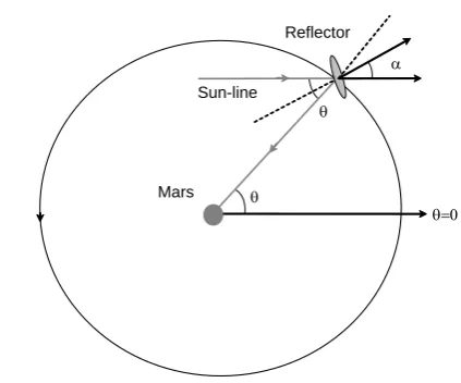
3. Solar Reflector Orbit Selection
3.1 Circular Orbit
In order to assess candidate orbits for solar reflectors, an evaluation
plane of Mars, a polar orbit normal to the ecliptic plane of Mars and
static equilibria high above the poles of Mars. For a reflector on a
circular orbit, with the reflector position defined by polar angle θ
relative to the Sun-line, the reflector is oriented such that α =θ 2 in
order that reflected solar radiation is directed towards the surface of
Mars, as shown in Fig. 6.2. For a reflector of area A, on a circular
orbit of period T, the mean energy transfer ∆E per unit time is
there-fore given by
( )
dtSA T T
E T
C
∫
= ∆
0 cos 2
1 θ (6.3)
However, the orbital angular velocity ω =dθ dt is related to the
or-bit period T such that ω =2π T so that
( )
θ θω
π
π d
T SA T
E
C
∫
+ −
= ∆
2
cos (6.4)
Therefore, performing the integration, the mean energy transfer ∆E
per unit time is given by
SA T
E
C π
2
=
∆ (6.5)
It can be seen from Eq. (6.5) that approximately 64% of the
maxi-mum available solar energy SA is transferred to the surface of Mars
Mars Climate Engineering using Orbiting Solar Reflectors 9
α
Reflector
Mars θ Sun-line
[image:9.595.139.351.152.328.2]θ=0 θ
Fig. 6.2. Solar reflector on a circular orbit in the ecliptic plane of Mars
3.2 Polar Orbit
For comparison, a circular polar orbit normal to the ecliptic plane of
Mars will now be considered, as shown in Fig. 6.3. Then, the
reflec-tor orientation can be fixed as the reflecreflec-tor orbits normal to the
Sun-line. This fixed orientation provides an additional benefit over orbits
in the ecliptic plane. The mean energy transfer ∆E per unit time for a
polar orbit is therefore given by
( )
α θ ωπ
d T
SA T
E
P
∫
=
∆ 2
0 cos
(6.6)
In order that the reflected solar radiation is directed toward the
sur-face of Mars (along the terminator) the reflector attitude α is fixed at
4
π
SA T
E
P 2
1
=
∆ (6.7)
It can be seen that approximately 71% of the maximum available
so-lar energy SA is transferred to the surface pf Mars. Evaluating the
ef-fectiveness of the circular and polar orbits it can be seen that
P
C T
E T
E < ∆
∆ (6.8)
so that polar orbits are in principle more efficient. A family of
dis-placed polar orbits will be considered later in Section 4. These orbits
are able to manage momentum transfer to the reflectors from solar
radiation pressure, which would otherwise lead to secular
[image:10.595.132.429.418.651.2]perturba-tions on the reflector orbit.
Mars Climate Engineering using Orbiting Solar Reflectors 11
3.3 Static Equilibria
An alternative to a Keplerian orbit about Mars is non-orbiting static
equilibria, as discussed by Zubrin and McKay (1997), based on a
concept by Forward (1991). These equilibria require that the solar
radiation pressure force exerted on the reflector is directly balanced
by the local gravitational force leading to a static equilibrium high
above the poles. While a detailed three-body analysis of such
equi-libria has been performed (McInnes et al. 1994), for static equiequi-libria
close to Mars (approximating a 2-body rather than 3-body problem)
the reflector normal must be directed along the Mars-reflector line to
ensure the correct force balance, assuming an ideal reflector.
How-ever, the orientation required for a non-ideal reflector to be
main-tained in static equilibrium leads to most of the reflected radiation
being directed away from the planetary body. Therefore, static
equi-libria do not appear to be a suitable location for Mars solar reflectors
(McInnes, 2002).
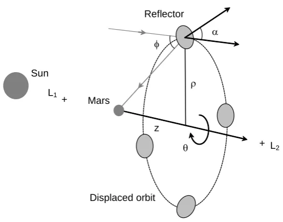
4. Families of Displaced Polar Orbits
In order to re-direct solar radiation to increase the total planetary
in-solation, reflectors must be deployed on suitable orbits, as discussed
in Section 3. One of the key issues is management of the momentum
accumulated by the reflectors due to solar radiation pressure, which
poses difficulties for reflectors deployed directly in Keplerian orbit
about Mars. In addition, since the reflectors act as mirrors, they will
distance of Mars from the Sun, the solar disk subtends an angle θ of
order 0.01 rad. Therefore, a reflector at distance d from the surface
of Mars will project a spot of diameter of order D~dθ , assuming a
perfectly flat reflecting surface. In order that the spot size is less than
the diameter of Mars, the distance d must be less than 1.4x10⁶ km, a
distance comparable to that to the L1 point. However, locations near
the L1 point are not attractive due to the long path length the
re-flected radiation must traverse and consequently the extremely high
pointing accuracy required for the solar reflectors. In addition, in
or-der to establish an artificial equilibrium point using solar radiation
pressure near L1, the aspect angle of the reflectors is rather large,
leading to a small projected reflector area (McInnes et al. 1994).
Artificial equilibria between Mars and the L2 point have been
considered by Zubrin, for heating the poles of Mars (Zubrin and
McKay 1997). However, as discussed in Section 3.3, when a
reflec-tor with non-ideal reflectivity is considered the required aspect angle
of the reflector is such that the re-direct radiation is in fact largely
unable to illuminate the poles (McInnes 2002).
As noted earlier, reflectors in orbit about Mars will be
strongly perturbed by solar radiation pressure. An attractive family
of orbits for solar reflectors are displaced orbits which can be
gener-ated by orienting the reflector such that a component of the solar
ra-diation pressure induced force exerted on the reflector is directed
normal to the orbit plane (McInnes and Simmons 1992). These
Mars Climate Engineering using Orbiting Solar Reflectors 13
α
ρ
z
Displaced orbit Reflector
Mars Sun
θ L1
L2
+
[image:13.595.134.411.152.369.2]+ φ
Fig. 6.4. Solar reflectors on a displaced polar orbit along the Sun-line.
Mars in the anti-Sun direction, as shown in Fig. 6.4 for a reflector
orbit radius ρ and displacement distance z. The momentum
accumu-lated by the reflector due to solar radiation pressure is offset by the
z-component of the local gravitational force. Using a two-body
analysis, the requirements for such displaced orbits can be
investi-gated. However, it is found that such orbits can also be established
using a full three-body analysis of the dynamics of the problem
(Bookless and McInnes 2004).
Using cylindrical polar coordinates, the equations of motion
for an ideal specular reflector can be written as
α α µ
ρ θ
ρ
ρ cos2 sin
2 2
a r
r +
− = −
0
2 =
+ ρθ θ
ρ (6.9b)
α
µ 3
2 acos
r r z
z +
− = (6.9c)
where µ is the product of the gravitational constant and the mass of
Mars. The reflector orientation is defined by a pitch angle α relative
to the Sun-line and the acceleration a induced by solar radiation
pressure is defined bya=2P σ where P is the solar radiation
pres-sure at the distance of Mars from the Sun (1.964x10⁻⁶ Nm-2) and σ is
the mass per unit area of the reflector. It is assumed that a is constant
(although the magnitude of the solar radiation pressure induced
ac-celeration scales as cos2α). For a circular displaced orbit it is
re-quired that ρ=0 and z=0. Therefore, defining the orbital angular
velocity ω =θ it can be shown that the required reflector pitch
an-gle and acceleration can be written as
3 2 2 ~ , ~ 1 tan r z µ ω ω ω ρ α = − = (6.10a) z z a 2 / 3 2 2 2 2 ~ 1 1 ~ − + = ω ω ρ ω (6.10b)
For the reflector to direct reflected light towards Mars, it is clear
from Fig. 6.3 that the reflector pitch angle α is related to φ such that
2
φ
α = . Assuming a perfect specular reflector, an image of the solar
Mars Climate Engineering using Orbiting Solar Reflectors 15
Mars-reflector line. The required reflector pitch angle is therefore
defined as = − z ρ α 1 tan 2 1 tan tan (6.11)
Since this orientation is defined a priori, the orbital angular velocity
of the reflector must now be a variable of the problem in order to
en-sure correct illumination of Mars by the reflector. Using Eq. (6.10a)
it can be seen that the orbital angular velocity required for this
de-sired reflector orientation is given by
2 / 1 tan 1 ~ − = α ρ ω
ω z (6.12)
The corresponding reflector acceleration can now be obtained from
Eq. (6.10b). A section of the surfaces of constant reflector
accelera-tion generated by this family of orbits is shown in Fig. 6.5 in the ρ-z
plane. Each point on a surface corresponds to a displaced orbit with
some radius ρ and displacement distance z in the anti-Sun direction.
It can be seen that the surfaces of constant reflector acceleration
have a rotational symmetry about the Sun-line, and that for a given
reflector acceleration a an orbit with a large radius and small
dis-placement is possible (α~45o), or an orbit with a small radius and
large displacement (α~0o). Clearly, displaced orbits with a small
pitch angle α are desirable to maximise the projected reflector area.
However, orbits with large displacements are found to be unstable,
displacement is still able to offset the momentum accumulated by
the reflector due to solar radiation pressure by the z-component of
the local gravitational force, while the orbit remains
Sun-synchronous with the orbit plane always normal to the Sun-Mars
line. While not considered further here, it is noted that if the
reflec-tor orbit period is chosen to be an integer number of sidereal days,
the spot projected onto the surface of Mars by the solar reflector will
follow a repeat ground track. This may have some importance if
[image:16.595.132.422.334.597.2]cer-tain regions are to be preferentially heated.
Mars Climate Engineering using Orbiting Solar Reflectors 17
5. Displaced Polar Orbit Stability
Now that a family of orbits with the appropriate reflector orientation
has been defined, its stability characteristics will be investigated.
This is achieved by linearising the equations of motion about the
nominal orbit to obtain a variational equation. The variational
equa-tion then describes the moequa-tion of the reflector in the neighbourhood
of the nominal orbit. The stability of the resulting trajectory may be
determined by examining the eigenvalues of the variational
equa-tion. If any of the eigenvalues are real and positive, the motion of
the reflector is exponentially divergent so that the orbit will be
un-stable. However, if all the eigenvalues are purely imaginary, the
re-flector is expected to remain bound in a neighbourhood of the
nomi-nal orbit. It should be noted that a linear anomi-nalysis is performed,
which in the present case provides only necessary conditions for
sta-bility, but sufficient conditions for instability.
The non-linear equations of motion will be linearised by
per-turbing the reflector from its nominal orbit with the reflector attitude
fixed in the rotating frame of reference (McInnes, 1999). In addition,
since the radiation field is uniform over the length-scale of the
prob-lem, the solar radiation pressure acceleration experienced by the
re-flector remains constant during the perturbation. Firstly, a
perturba-tion δ =
(
ξ,ψ,η)
will be added to the reflector position vector atsome point ro=(ρo,θo,zo) on the nominal orbit such that
δ + → o
o r
0
2 11 13
2 2
= +
+
− ωρ ψ ξ η
ξ M M dt d dt d o (6.13a) 0 2 2 2 = + dt d dt d o ξ ρ ω ψ (6.13b) 0 33 31 2 2 = +
+ ξ η
η
M M
dt
d (6.13c)
where the linear expansion coefficients are found to be
− + = 2 2 2
11 1 3
~ 3
r
M ω ω ρ
(6.14a) − =
= 2 2
31 13 ~ 3 r z M
M ω ρ (6.14b)
− = 2 2
33 1 3
~
r z
M ω
(6.14c)
Owing to the azimuthal symmetry of the problem all derivatives
with respect to θ in the linear expansion will vanish. Therefore, the
six terms M2,j and Mj,2 (j=1-3) are zero. The set of three coupled,
lin-ear ordinary differential equations defined by Eq. (6.13) may be
re-duced to two by integrating Eq. (6.13b) to obtain
) ( 2 o o dt
d ξ ξ
ρ ω
ψ =− − (6.15)
This equation is in effect a linearised form of Kepler's third law,
de-scribing the orbital angular velocity of the reflector relative to the
Mars Climate Engineering using Orbiting Solar Reflectors 19
then be substituted into Eq. (6.13a) to eliminate the azimuthal term.
However, this substitution then leads to a constant term 4ω2ξo in Eq.
(6.13a) so that the variational equation is no longer homogeneous. It
can be shown that the non-homogeneity can be easily removed by
re-scaling the co-ordinates through a change of variable
ξ ω ξ ξ 31 13 33 11 33 2 ' 4 M M M M M − − = (6.16a) ξ ω η η 31 13 33 11 13 2 ' 4 M M M M M − + = (6.16b)
Using this transformation a reduced variational system with a set of
two coupled equations is then obtained as
= + 0 0 ' ' 33 31 13 11 ' ' 2 2 η ξ η ξ M M M M dt d (6.17)
with the reflector free to drift along the nominal orbit in the
azi-muthal direction.
The stability of the family of orbits defined in Section 4 may
now be investigated by calculating the eigenvalues of the variational
equation. The eigenvalues may be obtained in the usual manner by
substituting an exponential solution of the form
( )
t o o λ η ξ η ξ exp ' ' = (6.18)Substituting this trial solution into Eq. (6.17) yields a matrix
= + + 0 0 33 2 31 13 11 2 o o M M M M η ξ λ λ (6.19)
For non-trivial solutions it is required that the determinant of this
matrix equation vanishes. The characteristic polynomial of the
varia-tional equation is then found to be
0 ) det( ) ( tr 2
4 + + =
M M λ
λ (6.20)
The stability characteristics may now be investigated by substituting
for the appropriate functional form of ω from Eq. (6.12). Then,
re-gions in the ρ-z plane may be identified where the roots of the
char-acteristic polynomial are purely imaginary with λj2<0 (j=1-4)
indi-cating stable, bound orbits. Such purely imaginary eigenvalues are
obtained if tr(M)>0 and det(M)>0, again noting that only a linear analysis is presented which provides necessary condition for
stabil-ity, but sufficient conditions for instability.
The family of displaced orbits is partitioned into stable and
unstable groups by the conditions tr(M)>0 and det(M)>0, denoted by the dashed line in Fig. 6.5. This partition between the stable and
unstable orbits is approximated by the boundary ρ=4z, with stable
orbits in the region ρ>4z. It can be seen then that only orbits
rela-tively close to the planetary terminator are linearly stable, while
or-bits with a large displacement are unstable. Clearly, it is
advanta-geous to use stable orbits to avoid the need for active control and to
mitigate against the risk of failure. Any failure in such an active
Mars Climate Engineering using Orbiting Solar Reflectors 21
a catastrophic loss of the reflector system. However although
unsta-ble, it can be shown that the orbits are strictly controllable (McInnes,
1999).
6. Solar Reflector Fabrication
The mass required to fabricate a solar reflector utilizing the
pas-sively stable orbit discussed above will now be considered. For an
orbit with a radius ρ of 15 Mars radii and a displacement z of 2 Mars
radii in the anti-Sun direction, Eq. (6.10b) shows that an acceleration
of 5.05 mms-2 is required. If an orbit with a smaller displacement is
considered then the required reflector mass will rise sharply, while a
larger displacement will soon lead to an unstable orbit as the
parti-tion between the stable and unstable orbits is reached. At the mean
distance of Mars from the Sun the solar radiation pressure P exerted
on a perfectly absorbing surface is 1.964x10⁻⁶ Nm-2. For an ideal
specular reflector of mass per unit area σ, the resulting acceleration
a is just 2P σ . Therefore, to generate an acceleration of 5.05 mms
-2
, the required mass per unit area σ of the reflector will be 1.01 gm-2.
This is a value similar to the canonical 1 gm-2 requirement for high
performance deployable solar sails (McInnes, 1999). The pitch of
the solar reflector α can also be obtained from Eq. (6.11) and is
found to be 41.2o. The required reflector area to obtain a given
in-crease in solar insolation Q can therefore be obtained from
α
cos S
reflector area is found to be 1.44x10¹³ m2. Again, a large number of
reflectors are envisaged, distributed azimuthally about the displaced
orbit to provide the total required surface area. The mass of the
re-flector can now be obtained from the required rere-flector mass per unit
area as σQ Scosα , where σ is obtained from the required reflector
acceleration as 2P a. For the orbit of interest the total reflector
mass is found to be 1.120x10¹⁰ kg. A comparison with large-scale
terrestrial engineering ventures in shown in Table 6.1, while a
com-parison with space-based geo-engineering schemes is shown in
Ta-ble 6.2.
Clearly, the fabrication of a reflector with a total mass of
or-der 1010 kg would require an advanced industrial space capacity with
the ability to exploit extraterrestrial resources. For example, the
mass requirements for the solar reflector can be satisfied by M-type
asteroids, which are relatively abundant in Nickel-Iron materials
(Gehrels, 1979). Assuming that the reflector is fabricated from thin
metallic film processed from such a body, and that the asteroid has a
bulk density similar to that of Iron (7860 kg m-3), an asteroid with a
radius of order 70 m will provide the required mass. Including a
non-metallic content of as much as 50% will increase the required
asteroid radius to order 90 m. The asteroid would require to be
proc-essed in-situ, probably using solar heating, and the metallic products
extruded into thin film for fabrication of the solar reflector elements.
Again, assuming a density of order 1 gm-2, the film thickness would
Mars Climate Engineering using Orbiting Solar Reflectors 23
challenging, but ultimately it is the film thickness which drives the
total mass of the reflector system. Terrestrial experiments have been
performed to produce thin metallic film of comparable thickness,
al-though only on a laboratory scale (Drexler 1979).
Lastly, it is interesting to speculate as to the effect of such a
displaced ring of orbiting solar reflectors on the sky, as seen from
the surface of Mars. For an observer near the equator, the tip of the
ring will slowly rise above the eastern horizon, and would likely be
rather dim in the darkening dusk sky due to diffusely scattered light.
Since the ring is composed of a vast number of individual reflectors,
it would like appear as a dense ribbon of point sources, packed
denser than the Pleiades. As local sunset is reached the ring would
brighten relative to the darkening sky and gradually rise until it
formed a thin bright arc stretching from the northern horizon to the
south. Since the orbit of the ring is displaced, the peak brightness of
the ring would occur sometime after sunset, providing a
spectacu-larly bright structure in the night sky. After peak brightness, the ring
would begin to dim, drifting westwards and sinking again towards
the horizon. This spectacular display would then be repeated prior to
[image:23.595.168.426.591.665.2]dawn with the ring providing a brilliant precursor to local sunrise.
Table 6.1. Mass comparison with terrestrial engineering ventures Scale Mass (kg) Engineering venture
108 6.5x10⁸ ‘Knock Nevis’ oil tanker (fully laden) 108 6x10⁹ Great pyramid of Giza
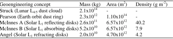
Table 6.2. Mass comparison with terrestrial geo-engineering
Geoengineering concept Mass (kg) Area (m2) Density (g m-2) Struck (Lunar L4/5 dust cloud) 2.1x10¹⁴ - -
Pearson (Earth orbit dust ring) 2.3x10¹² 1.10x10¹⁴ - McInnes A (Solar L1 reflecting disks) 2.6x10
11
6.57x10¹² 40.2 McInnes B (Solar L1 absorbing disks) 5.2x10¹⁰ 6.57x10¹² 7.9 Angel (Solar L1 refracting disks) 2.0x10¹⁰ 4.70x10¹² 4.2
7. Conclusions
Large-scale Mars terraforming using orbiting solar reflectors has
been considered. In particular, a family of displaced planetary orbits
has been presented which are suitable for use by solar reflectors as
part of a large Mars terraforming effort. The orbits are configured to
ensure that solar radiation is continually reflected onto the planetary
surface to increase the total solar insolation. A particularly useful
stable family of orbits has been identified which lie close to the
planetary terminator. For comparison, static equilibria have been
considered as potential locations for Mars solar reflectors. However,
the reflector orientation required to ensure static equilibrium leads to
significant losses of reflected solar radiation which is not intercepted
by the planetary body. Static equilibria therefore have serious
prob-lems for use by Mars solar reflectors, while displaced orbits can be
configured to be Sun-synchronous and passively stable leading to
benefits for their use in large-scale terraforming.
References
Mars Climate Engineering using Orbiting Solar Reflectors 25
Badescu V (2005) Regional and seasonal limitations for Mars intrinsic ecopoiesis. Acta Astronautica. 56, 670-680.
Birch P (1992) Terraforming Mars quickly. J British Interplanetary Society. 45, 331-340.
Bookless J and McInnes CR (2004) Dynamics, stability and control of displaced non-Keplerian orbits, IAC-04-A.7.09, 55th International Astronautical Con-gress, Vancouver.
Drexler KE (1979) High Performance Solar Sails and Related Reflecting Devices, 4th Princeton/AIAA Conference on Space Manufacturing Facilities, Princeton, Paper AIAA-79-1418.
Early JT (1989) Space-based solar shield to offset greenhouse effect, J British In-terplanetary Society. 42, 567-569.
Fogg M (1992) A synergestic approach to terraforming Mars. J. British Interplane-tary Society. 45, 315- 329.
Fogg MJ (1995) Terraforming: Engineering Planetary Environments, SAE Inter-national, ISBN 1-56091-609-5.
Forward RL (1991) Statite: A Spacecraft That Does Not Orbit. J Spacecraft and Rockets. 28, 606-611.
Gehrels T (1979) Asteroids. Univ. of Arizona Press, Tucson.
Gerstell MF, Francisco JS, Yung YL, Boxe C and Aaltonee ET (2001) Keeping Mars warm with new super greenhouse gases, Proc. Natl. Acad. Sci. USA. 98, 2154-2157.
Mautner M and Parks K (1990) Space-based control of the climate, Proc. Space 90, Amer. Soc. Civ. Eng. 1159-1169.
McInnes CR (1991) Solar Sail Halo Trajectories: Dynamics and Applications, 42nd International Astronautical Congress, Montreal, Paper IAF-91-334.
McInnes CR and Simmons JFL (1992) Halo Orbits for Solar Sails II - Geocentric Case. J Spacecraft and Rockets, 29, No. 4, 472-479.
McInnes C.R (1999) Solar Sailing: Technology, Dynamics and Mission Applica-tions, Verlag Series in Space Science and Technology, Springer-Verlag, ISBN 1-85233-102-X.
McInnes CR (2002) Non-Keplerian orbits for Mars solar reflectors. J British In-terplanetary Society. 55, 74-84.
McInnes CR (2006) Planetary Macro-engineering using Orbiting Solar Reflectors', in Macro-Engineering: A Challenge for the Future (ed. V. Badescu, R. Cath-cart and B. D. Schuiling), Springer-Verlag, ISBN 1-402-03739-2, pp. 215-250.
McKay CP, Toon, OB and Kastling JF (1991) Making Mars habitable. Nature, 352, 489-496.
Oberg JE (1981) New Earths: Restructuring Earth and Other Planets, New Ameri-can Library Inc, New York.
Sagan C (1961) The planet Venus. Science, 133, 849-858.
Sagan C (1973) Planetary engineering on Mars. Icarus.20, 513-514.