Int. J. Electrochem. Sci., 14 (2019) 3245 – 3252, doi: 10.20964/2019.04.54
International Journal of
ELECTROCHEMICAL
SCIENCE
www.electrochemsci.org
Short Communication
Advanced Co
3O
4interlayer as an efficient polysulfide barrier for
high-performance Li-S batteries
Li Xiao-qing*, Ma Yu-bo, Tang Cheng-li
Department of Chemical Engineering, Chongqing Chemical Industry Vocational College, ChongQing, 400020, China
*E-mail: [email protected]
Received: 9 December 2018 / Accepted: 29 January 2019 / Published: 10 March 2019
In this paper, Co3O4 powders were firstly prepared via hydrothermal reaction. Then, Co3O4 powder
was used as interlayer and applied into Li-S battery. Compared with that without interlayer, the Li-S battery assembled with the Co3O4 interlayer has a discharge capacity of 1201 mAh g-1 at the current
density of 0.1C. After 100 cycles at a current density of 0.1 C the discharge capacity is 706 mAh g-1,
which showing an excellent cycle performance.
Keywords: Li-S battery; Co3O4 interlayer; shuttle effect; electrochemical performance.
1. INTRODUCTION
Lithium-sulfur batteries have become one of the most promising lithium-ion batteries of the new generation due to their high theoretical capacity (1675 mAh g-1) and high energy density (2600 Wh kg-1) abundant reserves, low toxicity and no pollution [1, 2, 3]. However, their cathode material elemental sulfur has low electron conductivity and there is a "shuttle effect" of polysulfide during charge and discharge of the battery [4, 5, 6]. These shortcomings limit its use and development. In order to solve these problems, many strategies have been applied to inhibit the polysulfide dissolution. Linda Nazar firstly used CMK-3 as host material for sulfur to enhance the cycle performance of Li-S battery [7]. After that, the researchers paid much attention on the mesoporous carbon as host materials for elemental sulfur, such as carbon nanofiber [8-11], vapor grown carbon fiber [12, 13], hollow carbon spheres [14, 15, 16].
battery. As we all know, the separator acts as a barrier between the positive and negative electrodes of the battery [17, 18]. Consequently, the properties of interlayers will influence the electrochemical performance of Li-S battery. According to the previous studies about interlayers, a perfect interlayer can effectively suppress the polysulfide shuttle effect and plays an important role in the cycle life of the battery [19, 20, 21]. Tang and his colleagues used MoS2 functional interlayer to restrain the shuttle
effect. The Li-S battery using MoS2 functional interlayer remains at 401 mAh g-1 after 600 cycles,
showing an excellent cycle performance [22].
Inspired by the works of functional interlayer in Li-S battery, in our study, we have prepared a new functional Co3O4 interlayer, locating between sulfur cathode and separator. As an advanced
interlayer for Li-S battery, the polar metal sulfide Co3O4 has strong chemical adsorption to the
polysulfide, which can prevent the diffusion of polysulfide to a certain extent. As a result, using the Co3O4 interlayer is a promising method to inhibit the polysulfide shuttle effect.
2. EXPERIMENTAL 2.1 Synthesis procedure
1.6 g CoCl2•6H2O and 2.8 g Na2S2O3 were dissolved in a mixture of 10 ml distilled water and
30 ml ethanol while stirring for 4 hours. distilled water and 30 ml ethanol while stirring for 4 hours. Then, homogeneous solution was formed and transferred to a Teflon-lined stainless steel autoclave and heated at 180 °C for 24 h. After the reaction was completed, the autoclave was allowed to cool room temperature. Finally, the sample was collected by centrifugation and washed six times with water and ethanol, and dried in a vacuum oven at 60 °C for 12 h. As a result, Co3O4 powder was obtained.
After that, PTFE emulsion was mixed with as-prepared Co3O4 powder at a mass ratio of 2:1.
Then, the mixture was added into ethanol to form solution. After that, the solution was condensed into a plasticene-liked solid under magnetic stirring for 12 hours. The plasticene-liked solid was pressed into a film by a twin roller, dried at 70 ℃ in a vacuum, and finally punched into a Co3O4 interlayer
with a diameter of 15 mm.
2.2 Physical characterization
The as-obtained Co3O4 samples were characterized by using a scanning electron microscope
(SEM, JSM-7001F), an X-ray diffractometer (XRD, D8 Advance, BRUKER).
2.3. Electrochemical measurement
into circular electrodes. The batteries were assembled in an Air-filled glove box with lithium foil as anode, 1 mol/L LiTFSI/DME+DOL as the electrolyte, with Co3O4 interlayer. All electrochemical
measurements were carried out on a battery testing system (LAND CT 2001A) in the potential range from 1.5 V to 3 V.
3. RESULTS AND DISCUSSION 3.1 Structure and morphology
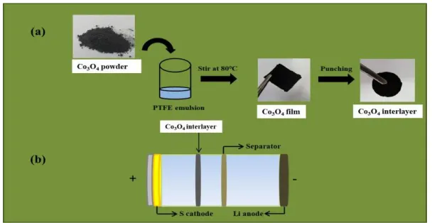
Figure 1 shows the preparation process of the Co3O4 interlayer and its application in Li-S
battery. As shown in Figure 1 a, the Co3O4 powder was firstly mixed with PTFE emulsion and ethanol.
Then, the solution was heated at 80 ℃ until the solution become plasticene-liked solid. After that, the plasticene-liked solid was pressed into a Co3O4 film by a twin roller, and finally punched into a Co3O4
interlayer with a diameter of 15 mm. Figure 1 b shows the application of Co3O4 interlayer in the Li-S
battery. It is located between the S cathode and separator.
Figure 1. The schematic for the preparation of Co3O4 interlayer.
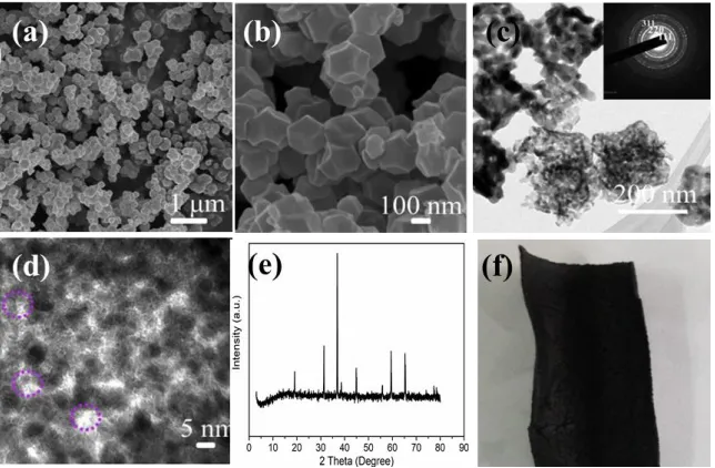
As shown in Figure 2 a and b, it can be seen that the Co3O4 material is consisted of
well-dispersed nano-particles, and the crystal particles form nanosheet-like structure. The size of Co3O4
powder particles range from 30-80 nm, indicating a narrow particle size distribution. The TEM images are shown in Figure 2c. The selected area electron diffraction (SAED) pattern (inset, Figure 2c) demonstrates that Co3O4 is polycrystalline. Figure 2d further exhibits the high magnification of
as-prepared Co3O4. Figure 2 e is the XRD diffraction pattern of Co3O4. It can be seen that Co3O4 material
has been successfully prepared [23, 24]. Moreover, the flexibility of as-prepared Co3O4 interlayer
could be observed in Figure 2f. Therefore, the Co3O4 interlayer could keep its shape after many
[image:3.596.147.451.369.526.2]
Figure 2. (a) and (b) The SEM images of Co3O4 at different magnification. (c) The XRD pattern of
Co3O4 at 2θ from 10° to 80°. (d) The flexibility of as-prepared Co3O4 interlayer.
3.2 Electrochemical performances
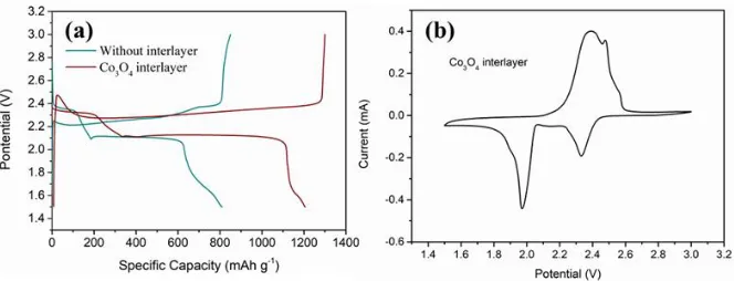
Figure 3 a represents the first discharge-charge profiles of Li-S battery using Co3O4 interlayer
and without interlayer at current density of 0.1 C. It can be seen that the initial discharge capacity of the battery Co3O4 interlayer and without interlayer is 1205 mAh g-1 and 806 mAh g-1, respectively.
Besides, the voltage platform at about 2.3 V corresponds to the transform of single sulfur substance to the long chain polysulfide, and the second voltage platform appears at about 2.1 V, which corresponds to the transition of long chain polysulfide to the short chain [25, 26]. Clearly, the discharge capacity of Co3O4 interlayer is higher than that of battery without interlayer, which is due to the efficient inhibition
of Co3O4 interlayer on the diffusion of polysulfide. The higher capacity value of the Co3O4 interlayer
confirms the efficient absorption for the soluble polysulfide.
Figure 3 b depicts the cyclic voltammetry curves of Li-S battery using Co3O4 interlayer at 0.1
mV s-1. It can be seen from the figure that the curves present the characteristic oxidation reduction
[image:4.596.140.462.70.281.2]
Figure 3. (a) The initial discharge-charge profiles of Li-S battery using Co3O4 interlayer and without
interlayer at current density of 0.1 C. (b) The cyclic voltammetry curves of Li-S battery using Co3O4 interlayer and without interlayer at a scan rate of 0.1 mV s-1.
Figure 4 shows the cycle performance of Li-S battery using Co3O4 interlayer and without
interlayer at the current density of 0.1 C. It can be seen that the capacity of the Co3O4 interlayer has the
higher retention rate than pristine separator and the capacity retention rate is 85% after 100 cycles, which could prove that the Co3O4 interlayer has a positive effect for the adsorption of polysulfide. This
is because the Co3O4 interlayer hinders the diffusion of polysulfide [29, 30]. Comparing the columbic
efficiency, it can be found that after 100 cycles of Co3O4 interlayer remains at 98%. The higher
columbic efficiency also indicates that Co3O4 interlayer has a good inhibition on the "shuttle effect" of
polysulfide and prevents polysulfide from spreading to the negative electrode [31, 32]. As we all know, the cycle stability is the key index for the lithium-ion battery. Long cycle performance is beneficial for the application of Li-S battery in the energy storage market.
Figure 4. The cycle performance of Li-S battery using Co3O4 interlayer and without interlayer at the
current density of 0.5 C.
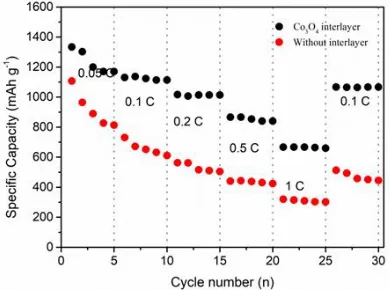
In order to characterize the rate performance of Co3O4 interlayer, the rate performance at
various current densities was conducted. The rate performance is another important factor for the Li-S battery. As shown in Figure 5, it can be seen that the current densities increase from 0.05 C to 1 C, and then return back to 0.1 C. As the current densities increase, the capacity decreases after the first charge and discharge [33, 34]. In terms of the Co3O4 interlayer, at the density of 0.5 C, the capacity is
[image:5.596.133.465.70.197.2] [image:5.596.190.409.452.596.2]
indicating that using Co3O4 interlayer has an excellent rate performance. However, for the battery
[image:6.596.200.395.123.268.2]without interlayer, the capacities fade rapidly with the increase of the current densities from 0.05 C to 1C.
Figure 5. The rate performance of Li-S battery using Co3O4 interlayer and without interlayer at various
current densities from 0.05 C to 1 C.
As is known to all, all EIS consist of two parts, that is, the semicircle in the high frequency region and the slant line in the low frequency region. The semicircle in the high frequency region indicates the charge transfer resistance between the electrode material and the electrolyte interface, and is expressed by the charge transfer impedance (Rct); the slant line in the low frequency region represents the impedance of the Li+ diffusion in the electrode, and is represented by the Warburg impedance [35]. Figure 6 is the electrochemical impedance spectra of Co3O4 interlayer and without
interlayer. The semicircle diameter of Co3O4 interlayer is much smaller than that of without interlayer,
demonstrating superior electronic conductivity. Therefore, this design could enhance the conductivity of the whole Li-S battery and promote the transportation of eletronics.
Figure 6. The EIS spectra of Li-S battery using Co3O4 interlayer and without interlayer.
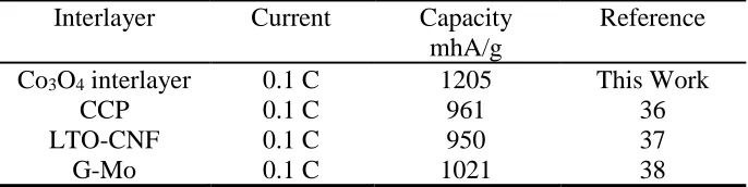
To clearly demonstrate the superior electrochemical performance of Co3O4 interlayer in the
[image:6.596.182.413.497.672.2]
value is much higher than other reported interlayers in the literature. This is mainly due to the presence of Co3O4 interlayer in the Li-S batteries. It could act as an efficient barrier for inhibiting the shuttle
[image:7.596.110.453.184.270.2]effect of soluble polysulfide in the electrolyte. As a result, the capacity value of the Li-S batteries is greatly improved by using the Co3O4 interlayer.
Table 1 The electrochemical performance of various functionalized interlayer for Li-S batteries.
Interlayer Current Capacity mhA/g
Reference Co3O4 interlayer 0.1 C 1205 This Work
CCP 0.1 C 961 36
LTO-CNF 0.1 C 950 37
G-Mo 0.1 C 1021 38
4. CONCLUSIONS
In summary, the main study was focused on the employment of Co3O4 interlayer for
high-performance lithium sulfur battery. In order to study the effect of improving the cycle high-performance of the lithium sulfur battery, Co3O4 interlayer was introduced as an efficient polysulfide barrier. The
electrochemical results exhibit that the Co3O4 interlayer has superior adsorption ability for polysulfide
and enhances the cycle performance at the same time. Compared with the without interlayer, the Co3O4
interlayer shows high specific capacity of 706 mAh g-1 after 100 cycles at 0.1 C.
ACKNOWLEDGMENTS
This study received financial support from Chongqing Chemical Industry Vocational College
References
1. Y. Zhang, Z. Gao, N. Song and J. He, Mater. Today Energ., 9 (2018) 319.
2. H. Zhao, N. Deng, J. Yan, W. Kang and J. Ju, Chem. Engineer J., 347 (2018) 343. 3. R. Xu, Y. Sun, Y. Wang, J. Huang and Q. Zhang, Chinese Chem. Lett., 28 (2017) 2235. 4. Q. Li, F. Zeng, Y. Guan and Z. Jin, Energ. Storage Mater., 13 (2018) 151.
5. Y. An, Y. Tian, H. Fei, G. Zeng and H. Duan, Mater. Lett., 228 (2018) 175. 6. Z. Xu, J. Kim and K. Kang, Nano Today, 19 (2018) 84.
7. Z. Ding, D. Zhao, R. Yao and C. Li, Int. J. Hydrog. Energ., 43 (2018) 10502. 8. W. Li, Y. Pang, T. Zhu, Y. Wang and Y. Xia, Solid State Ionics, 318 (2018) 82.
9. S. Zhao, P. Li, J. Adkins, L. Zhu, F. Du, Q. Zhou and J. Zheng, J. Electroanal. Chem., 823 (2018) 422.
10.S. Liu, X. Hong, D. Wang, Y. Li, J. Xu, C. Zheng and K. Xie, Electrochim. Acta, 279 (2018) 10. 11.C. Taso, C. Hsu, J. Zhou, C. Chin, P. Kuo and C. Chang, Electrochim. Acta, 276 (2018) 111. 12.G. Li, Z. Chen and J. Lu, Chem 4 (2018) 3.
13.T. G. Jeong, Y. S. Lee, B. W. Cho, Y. T. Kim and K. Y. Chung, J Alloy Compd., 742 (2018) 868. 14.Z. Li, Y. Lee, B. Cho, Y. Kim and H. Jung, J. Energ. Chem., 26 (2017) 1267.
16.A. Song, Y. Huang, X. Zhong, H. Cao, B. Liu, Y. Lin, W. Wang and X. Li. J. Membrane Sci., 556 (2018) 203.
17.N. Akhtar, H. Shao, F. Ai, Y. Guan and Q. Peng, Electrochim. Acta, 282 (2018) 758. 18.R. Wu, S. Chen, J. Deng, X. Huang, Y. Song and R. Gan, J. Energ. Chem., 16 (2018) 15. 19.W. Ren, W. Ma, S. Zhang and B. Tang, Chem. Eng. J., 341 (2018) 441.
20.J. Park, S. Yu and Y. Sung, Nano Today, 18 (2018) 35.
21.Z. G. Xu, Z. Geng, G. H. Yi, C. Chen, M. Z. Xue, B. Li and C. M. Zhang, Int. J. Electrochem. Sci., 12 (2017) 4515.
22.J. Xu, W. Zhang, H. Fan, F. Cheng, D. Su and G. Wang, Nano Energ., 51 (2018) 73.
23.L. M. Yang, Z. L. Chen, D. Cui, X. B. Luo, B. Liang, L. X. Yang, T. Liu, A. J. Wang and S. L. Luo, Chem. Eng. J., 359 (2019) 894.
24.X. B. Luo, C. C. Wang, L. C. Wang, F. Deng, S. L. Luo, X. M. Tu and C. T. Au, Chem. Eng. J., 220 (2013) 98.
25.Y. Liu, Y. Lee and K. Cho, Appl. Surf. Sci., 9 (2018) 16.
26.Q. Sun, Y. Yang, Z. Zhao, Q. Zhang, X. Zhao, G. Nie, T. Jiao and Q. Peng, Environ. Sci: Nano,10 (2018) 2440.
27.N. Li, X. He, K. Chen, S. Chen and F. Gan, Mater. Lett.,228 (2018) 195.
28.N. Li, F. Gan, P. Wang, K. Chen, S. Chen and X. He, J. Alloy Compud., 754 (2018) 64.
29.N. Li, S. F. Tang, Y. D. Rao, J. B. Qi, P. K. Wang, Y. Jiang, H. M. Huang, J. M. Gu and D. L. Yuan. Electrochim. Acta, 270 (2018) 330.
30.H. Zhang, P. Zuo, J. Hua, Y. Ma, C. Du, X. Cheng, Y. Gao and G. Yin, Electrochim. Acta, 238 (2017) 257.
31.P. H. Shao, J. Y. Tian, F. Yang, X. G. Duan, S. S. Gao, W. X. Shi, X. B. Luo, F. Y. Cui, S. L. Luo and S. B. Wang, Adv. Funct. Mater., 28 (2018) 1705295.
32.J. Xu, B. Jin, H. Li and Q. Jiang, Int. J. Hydrogen Energ., 42 (2017) 20749. 33.M. Feng, H. Li, M. Huang, J. Kang and H. Feng, Mater. Res. Bull., 99 (2018) 429.
34.Y. Lu, S. L. Shi, F. Yang, T. Y. Zhang, H. Y. Niu, T. Wang, J. Alloy compd., 767 (2018) 23. 35.D. Chen, R. Yang, L. Chen, Y. Zou, B. Ren and L. Li, J. Alloy Compud., 746 (2018) 116. 36.S. Q. Li, G. F. Ren, M. N. Hoque, Z. H. Dong and Z. Y. Fan, Appl. Surf. Sci., 396 (2017) 637. 37. D. C. An, L. Shen, D. N. Lei, L. H. Wang, H. Ye, B. H. Li, F. Y. Kang and Y. B. He, J. Energ.
Chem., 598 (2018) 30286.
38.X. Y. Yue, X. L. Li, J. K. Meng, X. J. Wu and Y. N. Zhou, J. Power Sources, 397 (2018) 150.