INTERNATIONAL CONFERENCE ON ENGINEERING DESIGN ICED 99 MUNICH, AUGUST 24-26, 1999
A METHODOLOGY FOR DESIGN COORDINATION IN A DISTRIBUTED
COMPUTING ENVIRONMENT
G. Coates, A.H.B. Duffy, R.I. Whitfield, W. Hills
Keywords: Design Coordination, Design Agents, Distributed Computing Environment
1. Introduction
At the conceptual stage of the design process it is increasingly common that analysis tools are involved in the evaluation of a large number of alternative designs. Designers use such analysis tools to assist with large scale concept evaluations and the prediction of good initial designs. Consequently there exists a need to coordinate these analysis tools to enable the early stage of design to be performed in a timely and efficient manner.
This paper describes a generic methodology that allows the management and coordination of design analysis tools. A Computer Aided Design tool, namely the Design Coordination System (DCS), has been developed to assist the designer in performing computational analysis in a distributed computing environment. Within the DCS, a collection of design agents act as members of a multi-functional team operating in a cooperative and coordinated manner in order to satisfy the objective of efficiently performing the design analysis.
2. Methodology
Design coordination can be viewed as the decision making, controlling, modelling and planning/scheduling activities with respect to the design factors time, tasks, resources and aspects [1], [2]. The methodology implemented within the DCS embraces this high level concept in that it involves the coordination of analysis tools which aims to optimise the scheduling and planning of the computational design analysis with respect to the allocation and utilisation of available resources. The DCS incorporates an agent architecture consisting of a suite of disparate design agents operating within a distributed and heterogeneous computing environment. Each design agent fulfils a particular role and performs several different tasks. The behaviour of all design agents is complimentary in that they assist other design agents when necessary. Agent communication is facilitated by a message passing mechanism. Design agents are able to send and receive messages and take appropriate action when required. An ontology is used in agent communication which defines a dictionary of terms that are meaningful and unambiguous. The DCS is flexible in that it can be utilised within existing design software packages, as will be discussed later, and/or as an external design support system.
indicates those design agent types and the communication flow between them.
Figure 1. DCS Agent Architecture
In any application of the DCS, the number of certain design agent types is fixed whereas others are dependent on factors such as the analysis tools being utilised to solve the design problem and the available resources in the computing network environment. Only one Framework Manager and Resource Manager operate within the DCS. The number of Distribution Agents is equivalent to the number of different analysis tools being utilised. A Tool Manager exists for each instance of a particular analysis tool. Each processor being employed by the DCS is allocated a Network Monitor.
As shown in Figure 1, the Framework Manager is central to all design agent activity within the DCS. In order for a design agent to register it’s services, initially it must send a message to the Framework Manager. Information contained within this initial communication relates to attributes of the design agent. This information, which is dependent on the type of design agent, is registered by the Framework Manager in an address book. Once a design agent’s attributes have been recorded, the Framework Manager acknowledges the existence of the said design agent. Subsequently, in the event of any one design agent requiring particular information regarding another design agent the details can be obtained from the Framework Manager. Knowledge of this information then enables the necessary design agents to communicate directly, rather than via the Framework Manager, and work cooperatively to perform their tasks and achieve their goals. This feature of design agents having the ability to communicate with any other design agent allows efficient message passing, removes the problem of communication bottlenecks, and promotes design coordination.
Design agents directly interacting with the analysis tools are the Distribution Agent and Tool Manager, which prepare and invoke the computational analysis respectively. A relationship exists between these types of design agent if they are associated with the same analysis tool. A Distribution Agent’s responsibilities include preparing temporary directories in which the design analyses is to be performed and coordinating the input and auxiliary files associated with the analysis tool to which it has been assigned. A Tool Manager’s duties include requesting design concepts from it’s related Distribution Agent and subsequently executing the instance of the analysis tool in the appropriate directory on the allocated processor. Once a design concept has been evaluated by a Tool Manager, the related Distribution Agent coordinates the result. Design concepts continue to be requested from the Distribution Agent by each related Tool Manager until all have been dispensed and evaluated.
The design agents responsible for dealing with the available resources are known as the
Framework
Tool
Manager
Network
Distribution
Monitor
Manager Agent
Resource Manager and Network Monitor. The functions of these two types of design agent are currently incomplete although they will be extended with the introduction of an Optimisation/ Scheduling Agent. The Resource Manager’s functions include constructing an analysis tool matrix and a processor matrix. The analysis tool matrix contains information such as measured dependencies between analysis tools and datum execution times of each analysis tool, which is very much akin to the representation of the design structure matrix [3]. The Resource Manager uses the information held in this matrix to establish an order of execution depending on the relationships between analysis tools. Hence, the Resource Manager can then identify those analysis tools that can be executed simultaneously. In the case of the problem being considered in the following section, a single analysis tool is used and therefore no dependencies exist. The processor matrix contains coefficient and efficiency measures for each processor available for use within the DCS. A coefficient is a relative measure of processor power and is fixed. Efficiency is a function of the coefficient and a processor’s work load, which may vary throughout the operation of the DCS. One influence on the work load of a processor is that of network usage attributed to other users. Due to the uncertainty of such other network usage, the efficiency of a processor is variable. Unless specifically requested, the Resource Manager is periodically notified of changes in a processor’s efficiency by Network Monitors, which observe and record the activity of the processor they have been assigned. Presently, this network information is used to indicate the utilisation of each processor although it is intended that greater use will be made once the aforementioned Optimisation/Scheduling Agent is functional within the DCS. Scheduling, load balancing techniques, and a genetic algorithm, will be employed by the Optimisation/Scheduling Agent to facilitate the dynamic allocation and optimum utilisation of the available resources. The Optimisation/Scheduling Agent views the scheduling problem as the total run time, of a given number of analysis tools with interdependencies between them, should be minimised by assigning them to be executed on an optimum number of the most efficient processors. Additional responsibilities will then be given to the Distribution Agent(s) such as directing related Tool Managers to perform their share of the design analysis on a particular processor.
3. Design Problem
4. Results and Discussion
The measure of performance of the DCS used was the elapsed time to compute the solution of a given number of design concepts. In an environment with dedicated processors, and based solely on computation time of the design concepts, as the number of processorsnis increased the elapsed time should decrease according to the inverse relation1/n.
[image:4.842.76.520.567.723.2]Benchmark results were obtained using a single Ultra 1/170 machine to sequentially compute 79 and 243 concepts for Case 1 and Case 2 respectively. The results presented in Table 1 were obtained by running the DCS in comparable conditions for each operation with respect to processor utilisation. That is, it was ensured that other network usage was negligible.
Table 1. DCS Performance Measurement
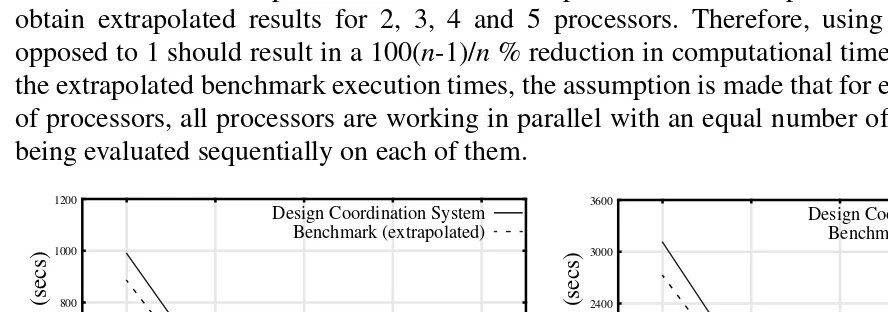
Figures 2 and 3 indicate the total time taken for the family of design agents operating within the DCS to perform their individual activities including the analysis tool execution duration for all design concepts being evaluated. Extrapolated benchmark execution times are also shown. The inverse relationship between the number of processors and computation time was used to obtain extrapolated results for 2, 3, 4 and 5 processors. Therefore, using n processors as opposed to 1 should result in a 100(n-1)/n% reduction in computational time. With respect to the extrapolated benchmark execution times, the assumption is made that for each combination of processors, all processors are working in parallel with an equal number of design concepts being evaluated sequentially on each of them.
Figure 2. DCS & Benchmark (79 concepts) Figure 3. DCS & Benchmark (243 concepts)
Number of Processors
n
(an)
100(n-1)/n
(%)
Case 1 (79 design concepts) Case 2 (243 design concepts)
(bn) (cn) (dn) (an-dn) (en) (fn) (gn) (an-gn)
100(1-cn/b1) 100(1-fn/e1)
Benchmark (secs) DCS (secs) Reduction (%) Offset∆ (%) Benchmark (secs) DCS (secs) Reduction (%) Offset∆ (%)
1 0 885 990 -11.9 11.9 2725 3111 -14.2 14.2
2 50.0 - 506 42.8 7.2 - 1556 42.9 7.1
3 66.7 - 350 60.5 6.2 - 1070 60.7 6.0
4 75.0 - 270 69.5 5.5 - 804 70.5 4.5
5 80.0 - 230 74.0 6.0 - 670 75.4 4.6
0 200 400 600 800 1000 1200
1 2 3 4 5
Design Coordination System Benchmark (extrapolated) 0 600 1200 1800 2400 3000 3600
1 2 3 4 5
Design Coordination System Benchmark (extrapolated) Ex ecution T ime (secs) Ex ecution T ime (secs)
Clearly, and as expected, in both Figures 2 and 3 it can be seen that as the number of processors is increased, the DCS execution duration decreases. The results obtained using the DCS appear to exhibit the previously stated inverse relationship with respect to the number of processors utilised. The results indicate that the DCS is capable of achieving results in close proximity to the projected benchmark values for both Case 1 and Case 2. With respect to Case 1, the offset between the DCS and benchmark results vary from approximately 12% to 5.5%. For Case 2 the offset varies from approximately 14% to 4.5%. In both cases, the greatest difference exists when only a single processor is employed within the DCS. This particular scenario is unrealistic since there would be no requirement for the DCS if only one processor were available as it’s intended use is in a distributed computing environment. The need for operating the DCS can only be justified in the event of more than one processor being available. After discarding the single processor use of the DCS, it can be deduced from Table 1 that a relatively small offset range of 7.2% to 4.5% envelops both cases. This proportion of DCS operation is due to activities performed by design agents excluding analysis tool executions. Prior to any analysis tool execution, the Distribution Agent is tasked with preparing and coordinating the various design concept models throughout the distributed design environment. Similarly, evaluated concepts need to be coordinated for subsequent use, in this instance within the RCE framework, between analysis tool executions. In addition, certain activities of the Framework Manager, Resource Manager and Network Monitors need to be performed before any analysis tool executions can commence.
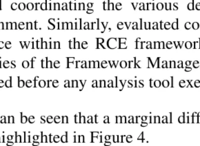
[image:5.842.196.401.398.548.2]In Table 1 it can be seen that a marginal difference in offset exists between Case 1 and 2. This difference is highlighted in Figure 4.
Figure 4. Offsets: Case 1 & Case 2
The discrepancy in offset between the two cases can be explained by the fact that the proportion of preparation and coordination activity performed by the Distribution Agent is less as a total percentage of the overall duration of the DCS in Case 2 than in Case 1. Approximately three times as many design concepts are evaluated in Case 2 as in Case 1 and therefore analysis tool computation time becomes more dominant. Hence, the greater the number of concepts being evaluated, the less the offset between the DCS and benchmark results.
5. Conclusion
The DCS has achieved significant reductions in the time taken to perform the computational 0
2 4 6 8 10
2 3 4 5
Case 1 Case 2
∆
(%)
analysis of a given number of design concepts within the RCE framework. Essentially, the time compression achieved by the DCS is inversely proportional to the number of processors utilised. As a result of significantly reducing the design analysis time, utilising the DCS has allowed the designer to perform a more comprehensive concept exploration of the design space. Consequently, the concept design selected was better in terms of the designer’s nominated criteria.
It has been shown that the family of design agents operating within the DCS can work cooperatively in a coordinated fashion with effective results. It is this ability of the design agents to operate in a coordinated manner that permits the computational analysis time to be reduced. Simply committing greater resources to a particular part of the design process will not necessarily result in an appropriate reduction in the time to perform the tasks involved. It is the capacity to coordinate the activity performed by each of the team members, taking into account the available resources and knowledge of their roles and effects, that enables a measured reduction in the duration of those activities to be achieved.
The current version of the DCS is being developed to promote even greater coordination within the context of the work described in this paper. This will be achieved with the introduction of an additional design agent type, namely the Optimisation/Scheduling Agent. This design agent will enable optimal resources to be allocated dynamically with respect to the design analysis. In addition, the DCS will be linked to an agent based Design Management System and an Integration framework in order to align coordinated activities with development plans, within an integrated environment.
Acknowledgements
This research is supported by the EPSRC and British Aerospace Military Aircraft.
References
[1] Duffy, A.H.B., Andreasen, M.M., MacCallum, K.J., & Reijers, L.N., “Design Coordination for Concurrent Engineering”, Journal of Engineering Design, Vol. 4 (No. 4), 1993, pp. 251-265.
[2] Andreasen, M.M., Duffy, A.H.B., MacCallum, K.J., Bowen, J., & Storm, T., “The Design Coordination Framework - key elements for effective product development”, Proceedings of the 1st International Engineering Design Debate, University of Strathclyde, Glasgow, UK. 23-24 September 1996.
[3] Steward, D.V., “The Design Structure System: A Method for Managing the Design of Complex Systems”, IEEE Transactions of Engineering Management, Vol. EM-28 (No.3), 1981, pp. 71-74.
[4] Whitfield, R.I., Coates, G., & Hills, W., “Multi-Objective Robust Concept Exploration within the Made-To-Order Sector”, Proceedings of the 12th International Conference on Engineering Design, 24-26 August 1999, Munich, Germany.
Mr. G. Coates
Engineering Design Centre, University of Newcastle upon Tyne, Newcastle upon Tyne. NE1 7RU
UNITED KINGDOM