International Journal of Innovative Technology and Exploring Engineering (IJITEE)
ISSN: 2278-3075, Volume-8 Issue-11, September 2019
Abstract - Compliant mechanisms and its systems are the focus of the active research. It describes a single elastic continuum used to transfer the motion and force mechanically. Their flexibility and stabilities are significant. Topology optimization Method is taken for designing the compliant mechanisms. It is a Material distribution approach for finding the optimum size and shape of the structure. The Author focused mainly on automotive application of Compliant Mechanism.i.e Design and implement of compliant clutch fork using topology optimization. Dimensional data is gathered in order to model the actual clutch fork. Compliant clutch fork designs are developed by reducing the weights compare to actual clutch fork with the help of topology optimization to get optimal compliant design. Experiments are directed to confirm the functionality of compliant clutch fork.
Index Terms: Compliant Mechanism, Topology Optimisation, Clutch Fork, Optimal Design, Reverse Engineering.
I.
INTRODUCTION
A compliant mechanism is a flexible structure that deforms
elastically to get its mobility from the deflection of flexible
members rather than from movable joints only [1][2]. For the
compliant mechanism, the input force is transferred to the
output port, much like the vice grips mechanism, only now
some energy is stored in the form of strain energy in the
flexible members [3]. The flexible segment built in such
mechanisms replaces the requirement of the various rigid
parts, pin joints and add-on-springs [4] and therefore it can
save considerable space, the less cost of parts due to usage of
less materials, assembly and labour [5]. The benefits of
compliance mechanism or devices will lead to reduction of
weight, noise, friction, wear and maintenance cost [6]. There
are various compliant mechanisms designed with a single
piece that replaces rigid link mechanism [7].
The
manufacturing
of
single
piece,
complaint
mechanisms of medium size devices, is done using injection
molding, rapid prototyping technology and method of
extrusion [8], or by the use of techniques like silicon surface
electroplating and micro machining. Even
though
the efforts
in designing and analyzing the compliant mechanisms are
very complex, still it is in
Revised Manuscript Received on September 06, 2019
S.Yuvaraja, Assistant Professor, School of Mechanical Engineering, Sathyabama Institute of Science & Technology, Chennai, India.
G.Arunkumar, Professor, School of Mechanical Engineering, Sathyabama Institute of Science & Technology, Chennai, India..
B.Venu Sai, Undergraduate Scholar, School of Mechanical Engineering, Sathyabama Institute of Science & Technology, Chennai, India.
P.Rajan, Undergraduate Scholar, School of Mechanical Engineering, Sathyabama Institute of Science & Technology, Chennai, India..
V.Dhinakaran, Department of Mechanical Engineering, Chennai institute of technology, Chennai, India.
.
practice because of its numerous advantages [9].
Most of the present designs are inherited on designer’s
instinct and knowledge of the current compliant mechanism
that must be achieved without the assistance of a recognized
synthesis method [10]. Several trial and error repetitions
using finite element models the desired mechanism
performance
is
obtained
[11].
Normally,
the
Kinematics-oriented tactics and Structural optimization
centered tactics are the two well-known methods available
for the compliant mechanisms systematic synthesis [12][15].
Moreover, spring lever model and spring-mass lever model
of Non-dimensional analysis with building block using
complaints ellipsoid and instant centre (IC) method
techniques are analyzed. Transferring an input force and
displacement at any part to an output and displacement at
another port complaint mechanisms becomes flexible
mechanisms [16].
Compliant Mechanism are joint less structure, so no need
of assembling and rubbing between two parts. The friction as
seem at the joints at rigid body mechanism is absent [17].
Compliant Mechanism used in various applications, because
they are cheaper, reduces the wear and tear and no need for
lubrication and it also reduces total number of parts required
to accomplish a specific task .Compliant Mechanism has
advantages of cost reduction and increased performance and
simplified manufacturing process.
Increasing performance includes increases it reliability in
reduced wear, weight and maintenance Compliant
Mechanisms are applicable in various fields such as handle
tools, robotics, medical, and electronics and for various
reasons [18].The main objective of the study is to explore the
development of Compliant Mechanism concept on
automotive compliant design with the help of topology
optimization.
II.
DESIGN
OF
ACTUAL
CLUTCH
FORK
USING
TOPOLOGY
OPTIMISATION
APPROACH
Topology Optimization is a tool that assists the designs
in the selection of suitable initial structure of topology by
removing (or) redistributing material of structural domain
[19] and the material of each element should take the value
of 0.1 or either 0.5.The designs of topology is also treated
as a layout optimization problem to search of the material
arrangement and connecting with in a design domain. The
design domain must me break down in such a manner so it
can be paramaterialised and mathematically represents in
a systematic fashion. The size and geometry of a given
clutch fork can be further optimized to improve functional
performance.
Design and Development of a Compliant
Clutch Fork using Topology Optimization
The user needs to define the structured problem (material
parts, FE Model, loads etc and the objective function (i.e.
the function to minimized or maximized)
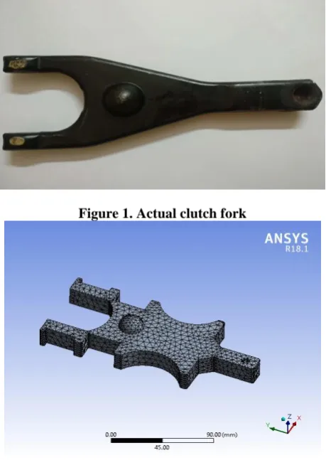
[image:2.595.54.284.87.411.2]Figure 1. Actual clutch fork
Figure 2.
The 3D Meshed Model of Clutch Fork
[image:2.595.313.541.113.300.2]
At present, the work is being carried to create, initial
topology domain, specification, maximum possible volume
of the material domain and to study the input location,
constraints and optimization. Here, the draw direction option
is used as a manufacturing constraint [20]. In this way the
material layout can be produced and can be oriented to a
particular direction. The other option is used for the study of
one plane symmetry. Longitudinal symmetry is defined on
the part for topology optimization. The optimization target is
maximization of the stiffness with a volume reduction of fork
to 50%.The optimized material mesh distribution is showed
in Figure2.Toplogy optimization as a leaning to create the
design proposals, as the material is accumulated in the outer
border in the areas of design space .The next step is
development of new clutch fork shape from the results of
topology optimization.
Figure 3.
Topology optimized domain of actual clutch fork
III.
REDESIGN
OF
MODERNIZED
CLUTCH
FORK
BASED
ON
THE
RESULT
OF
TOPOLOGY
OPTIMIZATION
Figure 4. Redesign of new clutch fork based on the results
of topology optimization.
Figure.4.shows the new geometry of clutch fork from the
results of topology optimization. Stress analysis verifications
are performed accurately to predict the operation of new
design
IV.
ANALYSIS
OF
COMPLIANT
MECHANISM
The dimensional data of modernized clutch fork is
gathered. Modernized clutch fork design will be used as a
datum for reference. Clutch fork is modeled with dimensional
data for actual dimension, size and shape. Topology
optimized model with the reference of the datum size and
shape the modern compliant clutch fork is designed with in
the designs space within the set of loads and boundaries.
In the modernized clutch design 50% mass or weight has
been reduced by topology optimization approach. The
conventional topology optimization formulation uses a finite
element method (FEM) to evaluate the design performance.
Using either gradient-based mathematical programming
techniques such as the optimality criteria algorithm and the o
non gradient-based algorithms such as genetic algorithms
design is optimized .
Structural analysis is done together for datum and
compliant clutch fork design .Figure5. Shows Cast iron has
been selected to the datum and Figure6. Polypropylene [ABS
Plastics] has been selected to compliant clutch fork and is
referred as Design A. All the boundary conditions and
loadings followed the actual working conditions of exists car
clutch fork. Assumption actual force 6N, 20N is applied at
back and centre of the clutch fork, 30N is applied as bearing
load.
Master CAM is used as to transfer all the shape
information of the design the CATIA. The experimental
model was used to observe the function and movement of
clutch fork. Simple testing is
[image:2.595.55.282.620.769.2]International Journal of Innovative Technology and Exploring Engineering (IJITEE)
ISSN: 2278-3075, Volume-8 Issue-11, September 2019
[image:3.595.310.544.50.195.2]the compliant clutch fork perform equally with the actual
clutch fork.
Figure 5. Datum design of optimized clutch fork
V.
RESULTS
AND
DISCUSSIONS:
[image:3.595.51.286.73.345.2]MASS OF DATUM & DESIGN A:
Figure.7.
Mass of Datum and Design A
[image:3.595.309.544.230.427.2] [image:3.595.315.537.462.671.2]Figure7.Shows the masses of both datum and complaint
clutch fork .As can been seen, the mass of design A is the
lowest with 40g compare with Datum. Design A is assigned
with ABS plastic material is more lighter compare with
Datum as it is assigned with cast iron material .However
lighter clutch fork is needed to maintain it function without
compromise on the mechanical strength
Figure 8.
Equivalent stress (Von-Misses stress) of Datum
Figure 8.
Equivalent stress(Von-Misses stress) of
Complaint Clutch Fork
Figure 8.1.Stress distribution on Datum and Design A
Figure.9.Total Deformation of Datum
Figure8.1. shows the stress distribution on clutch fork.
Design A has the lowest value of the Maximum equivalent
(von-mises) stress with 5.8692 MPa. This is much better than
comparing to datum design with 6.0977 MPa. Maximum
stress is an important criterion in design selection because
failure occur at the area where the higher stress
concentration,
with
the
[image:3.595.52.280.613.739.2]the appropriate design for complaint clutch fork
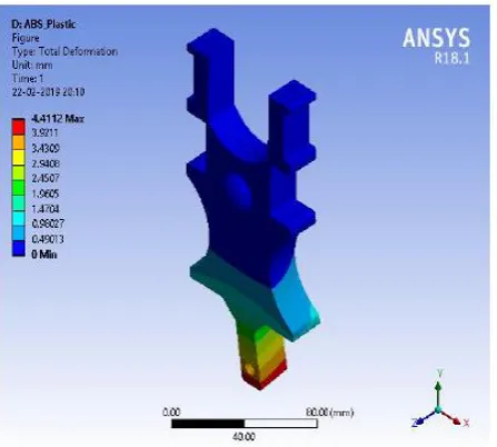
[image:4.595.58.282.122.323.2]Design A has the highest value of total deformation
compare with the datum. At the end of clutch fork highest
deformation is occurred. The fork with highest deformation
seems like flexible and will impact the mechanical strength of
the design.
Figure 9.1.Simulation results of total deformation;
Datum and Design A
Physical testing:
The appearance of experimental model is almost same as
datum only size and mass is reduced. The material used is
also different with the compliant clutch fork. The polymer
based materials are good with complaint design are
potentially to replace the cast iron based clutch fork due to
equal functioning.
VI.
CONCLUSION
Complaint mechanism by topology optimization is a great
design approach for reducing the mass and number of
components while maintaining the functions of modernized
clutch fork. The complaint clutch fork met the functional
requirement and mechanical strength as actual clutch fork
.Based on simple testing the compliant clutch fork
appearance and performance is quite same as datum. It also
has good deformation and equivalent stress which
maintaining structural stiffness
Besides reducing the mass of clutch fork, it also supports
the design for no assembly concept. Single part results no
assembly needed.So,it directly reduce the production cost
while using polymer materials decrease material cost
compare with the cast iron or steel based clutch fork. Polymer
based materials are relatively cheaper than cast iron or steel
based materials.
REFERENCES
1. A. Saxena and G. K. Ananthasuresh, “On the Extraction of Kinematic Behavior from Optimal Compliant Topologies with Application to Number Synthesis of Linkages,” in Proceedings of the ASME Design Engineering Technical Conference, 2001.
2. A. Saxena and G. K. Ananthasuresh, “On the Extraction of Kinematic Behavior from Optimal Compliant Topologies with Application to Number Synthesis of Linkages,” in Proceedings of the ASME Design Engineering Technical Conference, 2001.
3. B. K. Nagesha, V. Dhinakaran, M. Varsha Shree et al., Review on characterization and impacts of the lattice structure in additive
manufacturing, Materials Today: Proceedings,
https://doi.org/10.1016/j.matpr.2019.08.158
4. C. R. Mortensen, B. L. Weight, L. L. Howell, and S. P. Magleby, “Compliant mechanism prototyping,” Proc. ASME Des. Eng. Tech. Conf., pp. 1–10, 2000.
5. Dineshkumar, S., Sriram, S., Surendran, R., Dhinakaran, V."Experimental investigation of tensile properties of Ti-6Al-4V alloy at elevated temperature"International Journal of Recent Technology and Engineering 8(1), pp. 103-107(2019)
6. Erdmann G and sander N .Mechanism design analysis and synthesis Ed prentice Hall, Upper saddle river, NJ,1997.
7. G. Krishnan and G. K. Ananthasuresh, “An Objective Evaluation of Displacement-Amplifying Compliant Mechanisms for Sensor Applications,” 2006.
8. G. Krishnan and G. K. Ananthasuresh, “An Objective Evaluation of Displacement-Amplifying Compliant Mechanisms for Sensor Applications,” 2006.
9. Gowda, T., Jagadeesha, T., Dhinakaran, V."Optimization of design parameters of aircraft wing structure with large cut outs using damage tolerant design and finite element analysis approach"International Journal of Recent Technology and Engineering 8(1), pp. 128-132(2019)
10. Karthick, S. "Semi supervised hierarchy forest clustering and knn based metric learning technique for machine learning system", Journal of Advanced Research in Dynamical and Control Systems, vol. 9, no. Special Issue 18, pp. 2679-2690, 2017.
11. Kishore, R., Karthick, G., Vijayakumar, M.D., Dhinakaran, V."Analysis of mechanical behaviour of natural filler and fiber based composite materials"International Journal of Recent Technology and Engineering 8(1), pp. 117-121(2019)
12. L. L. Howell, S. P. Magleby, and B. M. (Brian M. Olsen, Handbook of compliantmechanisms
13. L. L. Howell, S. P. Magleby, and B. M. (Brian M. Olsen, Handbook of compliantmechanisms.
14. L. Yin and G. K. Ananthasuresh, “A novel formulation for the design of distributed compliant mechanisms,” in Proceedings of the ASME Design Engineering TechnicalConference, 2002.
15. L. Yin and G. K. Ananthasuresh, “A novel formulation for the design of distributed compliant mechanisms,” in Proceedings of the ASME Design Engineering TechnicalConference, 2002.
16. M. Frecker, “Optimal design of compliant mechanisms,” 1997. 17. M. Frecker, N. Kikuchi, and S. Kota, “Topology optimization of
compliant mechanisms with multiple outputs,” 1999.
18. M. Y. Benslimane, P. Gravesen, and P. Sommer-Larsen, “Mechanical Properties of Dielectric Elastomer Actuators With Smart Metallic Compliant Electrodes,” Proc.SPIE, vol. 4695, pp. 150–157, 2002. 19. Madan, D., Sivakandhan, C., Sagadevan, S., Sathish, T. “Ocean wave
energy scenario in India”, International Journal of Mechanical and Production Engineering Research and Development, vol. 2018, no. Special Issue, pp. 582-590, 2018.
20. Mageshwaran, G., Durairaj, R.B., Britto Joseph, G., Sathish, T. “An experimental investigation on thermai bonded joints of Ti-6AI-4V with SS304L”, International Journal of Mechanical and Production Engineering Research and Development, vol. 9, no. Special Issue 1, pp. 554-561, 2019.
21. Mohanavel, V., Suresh Kumar, S., Sathish, T., Anand, K.T. “Effect of ZrB2 content on mechanical and microstructural characterization of AA6063 aluminum matrix composites”, Materials Today: Proceedings, vol. 5, no. 5, pp. 13601-13605, 2018.
22. O. Sigmund, “On the Design of Compliant Mechanisms Using Topology Optimization*, Jan. 1997.
23. Roach,G M,Lyon ,SM,and Howell ,L,L.compliant overrunning clutch with centrifugal throw out,,(2000)
24. S. Canfield and M. Frecker, “Topology optimization of compliant mechanical amplifiers for piezoelectric actuators,” Struct. Multidiscip. Optim., 2000.
25. S. Dinesh Kumar, D. Chandramohan, K. Purushothaman and T. Sathish, "Optimal Hydraulic And Thermal Constrain For Plate Heat Exchanger Using Multi Objective Wale Optimization", Materials Today Proceedings, Elsevier Publisher, Accepted, 2019. DOI : 10.1016/j.matpr.2019.07.710.
International Journal of Innovative Technology and Exploring Engineering (IJITEE)
ISSN: 2278-3075, Volume-8 Issue-11, September 2019
27. S. Shuib, M. I. Z. Ridzwan, and A. H. Kadarman, “Methodology of compliant mechanisms and its current developments in applications: A review,” AmericanJournal of Applied Sciences, 2007.
28. Sathish, T. “BCCS Approach for the Parametric Optimization in Machining of Nimonic-263 alloy using RSM”, Materials Today: Proceedings, vol. 5, no. 6, pp. 14416-14422, 2018.
29. Sathish, T. “BONN Technique: Tribological Properties Predictor for Plasma Nitrided 316L Stainless Steel”, Materials Today: Proceedings, vol. 5, no. 6, pp. 14545-14552, 2018.
30. Sathish, T. “GAC-ANN Technique for Prediction of Spring Back Effect in Wipe Bending Process of Sheet Metal”, Materials Today: Proceedings, vol. 5, no. 6, pp. 14448-14457, 2018.
31. Sathish, T. “Performance measurement on extracted bio-diesel from waste plastic”, Journal of Applied Fluid Mechanics, vol. 10 , no. Special Issue, pp. 41-50, 2017.
32. Sathish, T. “Prediction of springback effect by the hybridisation of ANN with PSO in wipe bending process of sheet metal”, Progress in Industrial Ecology, vol. 12, no. 1, pp. 112-119, 2018.
33. Sathish, T., Chandramohan, D. “Experimental study and model development for on-line drill wear monitoring system using lab view”, International Journal of Recent Technology and Engineering, vol. 7, no. 6, pp. 281-286, 2019.
34. Sathish, T., Chandramohan, D. “Teaching methods and methodologies used in laboratories”, International Journal of Recent Technology and Engineering, vol. 7, no. 6 , pp. 291-293, 2019.
35. Sathish, T., Jayaprakash, J. “Meta-heuristic approach to solve multi period disassembly-to-order problem of end-of-life products using adaptive genetic algorithm”, International Journal of Mechanical and Mechatronics Engineering, vol. 15, no. 3, pp. 59-67, 2015.
36. Sathish, T., Jayaprakash, J. “Multi period disassembly-to-order of end-of-life product based on scheduling to maximise the profit in reverse logistic operation”, International Journal of Logistics Systems and Management, vol. 26, no. 3, pp. 402-419, 2017.
37. Sathish, T., Jayaprakash, J., Senthil, P.V., Saravanan, R. “Multi period disassembly-to-order of end of life product based on scheduling to maximize the profit in reverse logistic operation”, FME Transactions, vol. 45, no. 1, pp. 172-180, 2017.
38. Sathish, T., Mohanavel, V. “IWF based optimization of porous insert configurations for heat transfer enhancement using CFD”, Journal of Applied Fluid Mechanics, vol. 11, no. Specialissue, pp. 31-37, 2018. 39. Sathish, T., Muthukumar, K., Palani Kumar, B. “A study on making of
compact manual paper recycling plant for domestic purpose”, International Journal of Mechanical and Production Engineering Research and Development, vol. 8, no. Special Issue 7, pp. 1515-1535, 2018.
40. Sathish, T., Muthulakshmanan, A. “Modelling of Manhattan K-nearest neighbor for exhaust emission analysis of CNG-diesel engine”, Journal of Applied Fluid Mechanics, vol. 11, no. Specialissue, pp. 39-44, 2018. 41. Sathish, T., Periyasamy, P. “An extensive review of reverse logistics and its benefits in supply chain management”, International Journal of Mechanical and Production Engineering Research and Development, vol. 2018, no. Special Issue, pp. 165-178, 2018.
42. Sathish, T., Periyasamy, P., Chandramohan, D., Nagabhooshanam, N. “Modelling of cost based optimization system E-O-L disassembly in reverse logistics”, International Journal of Mechanical and Production Engineering Research and Development, vol. 2018, no. Special Issue, pp. 711-716, 2018.
43. Sathish, T., Periyasamy, P., Chandramohan, D., Nagabhooshanam, N. “Modelling K-nearest neighbour technique for the parameter prediction of cryogenic treated tool in surface roughness minimization”, International Journal of Mechanical and Production Engineering Research and Development, vol. 2018, no. Special Issue, pp. 705-710, 2018.
44. Sathish, T., Vijayakumar, M.D., Krishnan Ayyangar, A. “Design and Fabrication of Industrial Components Using 3D Printing”, Materials Today: Proceedings, vol. 5, no. 6, pp. 14489-14498, 2018.
45. Senthiil, P.V., Aakash Sirusshti, V.S., Sathish, T. “Artificial intelligence based green manufacturability quantification of a unit production process”, International Journal of Mechanical and Production Engineering Research and Development, vol. 9, no. 2, pp. 841-852, 2019.
46. Senthiil, P.V., Aakash Sirusshti, V.S., Sathish, T. “Equivalent stress prediction of automobile structural member using fea-ann technique”, International Journal of Mechanical and Production Engineering Research and Development, vol. 9, no. 2, pp. 757-768, 2019. 47. Sriram, G., Dhinakaran, V., Jagadeesha, T., Ramgopal, R."Finite
element simulation of temperature distribution and residual stress in single bead on plate weld trial using double ellipsoidal heat source model"International Journal of Recent Technology and Engineering 8(1), pp. 133-138(2019)
48. U. D. Larsen, O. Sigmund, and S. Bouwstra, “Design and fabrication of compliant micro mechanisms and structures with negative Poisson’s ratio,” J.
49. V. Dhinakaran, J. Ajith, A. Fathima Yasin Fahmidha et al., Wire Arc Additive Manufacturing (WAAM) process of nickel based superalloys – A review, Materials Today: Proceedings,
https://doi.org/10.1016/j.matpr.2019.08.159
50. Venkatesh, R., Vijayan, V., Parthiban, A., Sathish, T., Siva Chandran, S. “Comparison of different tool path in pocket milling”, International Journal of Mechanical Engineering and Technology, vol. 9, no. 12, pp. 922-927, 2018.
51. Vijayan, V., Parthiban, A., Sathish, T., Siva Chandran, S., Venkatesh, R. “Performance analysis in end milling operation”, International Journal of Mechanical Engineering and Technology, vol. 9, no. 11, pp. 2263-2271, 2018.