Software complexes and new approaches to
non-linear analysis of framed structures
Vladimir Meleshko1
1 Saint Petersburg State University of Architecture and Civil Engineering, Faculty of Civil Engineering, 190005 2nd Krasnoarmeiskaya st. 4, Russian Federation
Abstract. There is a great number of non-linear tasks which can be solved with the use of computer-based simulation and finite elements method (FEM). But in order to ensure high speed and accuracy of calculations it is necessary to use new mathematical models and algorithms. The analysis of the known FEM forms and approaches to numerical solution of tasks based on force method is performed in this work. Represented in the document is formulation of the finite-element stress method and algorithmization of the classical force method for calculation of framed structures based on the equation of strain compatibility – contour forces method. Statement of problems which can be more effective from the point of view of elastic-plastic deformations at numerical solution is considered. In particular, the hybrid finite-element method based on the generalized Mohr formula for determination of long bar stiffness coefficient with account of non-linear behavior. The main relationships for creation of finite-element method equation system in the form of force method are represented.
1 Introduction
The modern tendencies in modeling of building structures are characterized by continuous increase in dimensionality of the solvable problems which requires advanced development in the sphere of software products. The necessity of solving the problems within the acceptable terms becomes common practice in the engineering activity. Engineers must pay more and more attention to the model physics and mathematical computational algorithms.Solution of complex problems, non-linear in particular, would be challenging without implementation of the necessary mathematical models. Besides, the important factor is productivity of computer programs which is directly connected with the applied mathematical tool. All this stipulates a necessity in elaboration of new approaches to calculation of building structures the main role in development of which belongs to software complexes.
The finite-element method (FEM) is taken as a basis for strength analysis of structures in the modern software complexes. In order to determine the elastic-plastic deformation the use is made of FEM in the classical form of a deflection method [1]. The main unknown quantities here are displacements of junction points; stresses are of secondary importance and
shall be determined by numeric differentiation of displacements. But for non-linear problems the more convenient can be the hybrid FEM scheme in the form of displacement method [2, 3] and force method, especially in regard to obtaining stress values. The main advantage of FEM in the form of force method is that the main unknown values here are stresses. Besides, application of the Castigliano principle [4] gives the upper limit of the approximate solution (i.e. stresses are overstated), which is better at strength calculation than the understated value. The finite-element method belongs to the discrete analysis method. Unlike the rest numerical methods it is based on the physical discretization of the investigated area. The area, the continuous medium with an infinite number of the degrees of freedom, is replaced with a discrete model of interconnected finite elements with a finite number of the degrees of freedom which in aggregate determine the piecewise continuous interpolation function. Unlike classic variation methods [5] where selection of interpolation functions depends on configuration of the considered problem, this does not takes place in FEM since the interpolation functions are determined exclusively within individual finite elements. These functions represent a family of functions independent of one another which are taken as an element, so that their values along with all other elements, except for elements they belong to, equal to zero. This is the main distinction between FEM and classical numerical methods where the interpolation functions are taken for the whole area.
In order to carry out the elastic-plastic calculation it is necessary to know the fields of stress (force) occurring in the deformable body points. From the point of view of stress determination at numeric calculations, setting of problems in displacements has significant deficiency. Since the result of the approximate solution for such scenarios is displacement values in individual points (grid nodes) of the body, stress calculation is brought to numeric differentiation of functions set by points. This leads to loss of accuracy in stress (force) determination as compared to the accuracy of displacement determination.
One method to improve accuracy of stress determination at numeric solution is elaboration and application of problem scenarios in stresses (forces), i.e. such problem scenarios of the deformable solid body mechanics where the unknown functions are stresses immediately. This work is devoted to this very range of issues.
The variational formulation of elasticity problems in stresses – the principle of minimum complementary energy (Castigliano variational principle) is well known [6]. However, the conventionally extreme character of the Castigliano functionality makes creation of the finite elements and the analysis of FEM convergence significantly more complicated than that in the scenario of displacements. Studied in works [11, 12] is a possibility of obtaining the definitely extreme variational problem on the basis of Castigliano functionality with the use of penalty method. There are certain difficulties occurring here and connected with a necessity to select the optimum value of penalty parameter and application of discontinuous approximation of stresses. The known method to avoid a necessity in creation of statically admissible stress fields is application of stress functions. However, occurred in the functionality are the second derivatives from the required functions and it is necessary to use finite elements complicated enough for creation, which provide continuity of both the function itself and its first derivatives. Such element is considered in [11].
The FEM diagrams have gained practical application, where the Castigliano functionality is used, actually, as an auxiliary means for creation of the so called equilibrium finite elements of the displacement method. The hybrid FEM is studied in works [2, 3] with the use of generalized Mohr formula within the finite element for non-linear analysis of framed structures. Nevertheless, the variational problem based on the Castigliano functionality can be more effective for calculation of framed structures in the elastic-plastic domain than the classical FEM.Execution of two-value calculation on the basis of two opposite FEM forms makes it possible to obtain the two-way evaluation of the accurate solution of the corresponding problem.
A purpose of this work was to perform the analysis of the known approaches on the basis of force method, to show peculiarities of equation system generation. Consider the statement of problems which can be more effective from the point of view of elastic-plastic deformations at numerical calculation.
2 Numerical methods based on structural engineering force
method
2.1 Method of contour forces
Let's consider the contour force method proposed in [7] for algorithmization of classical force method. The main problem of the force method implementation on computer is conditioned by nonuniqueness of the main system selection.
The algorithm of the contour force method consists in direct generation of strain compatibility equations on the basis of the previously generated strain compatibility matrix of individual framed structure contours [8]. The matrix of the general solution of homogeneous equilibrium equations is created by transposition of compatibility equation matrix. As a result, no analysis of the nodal equilibrium equations matrix is required [L]. The yield matrix structure is unambiguously determined by numeration of the statically undeterminable contours of the system [8].
Let's write the node equilibrium equation for the framed structure
LT
P , (1)where {P} – a vector of external forces; {} – a vector of internal forces in bars; [L]T– a matrix of internal forces transformation according to the main coordinate axis.
The framed structure connected in nodes must remain connected in these very nodes after deformation as well. Equations showing this condition are called compatibility equations. Let's write geometrical constrained equations of nodes displacement with deformations of bars
L
U
eу e0, (2)
and physical equations
eу
e
, (3)where {U} – a column of nodes displacement; {еу} – a column of generalized displacements (deformation of bars);{е0} – a column of the specified initial deformations; [e] – a matrix of the specified bar yield coefficients.
Fig. 1. External and internal forces in the node.
The main problem of the force method algorithmization consists in generation of the common solution of the homogeneous equilibrium equations
LT 0, (4)For statically indeterminate systems a number of lines and the matrix rank [L]T is less than a number of columns and, consequently, the homogeneous equilibrium equations (4) have non-zero solutions. Let's assume that solutions of equations are obtained (4). Let's present these solutions as matrix lines [В], then, as defined by the system (4), the identity is true
LTBT 0, (5)or by transposition rules
B L 0. (6)Let's multiply equations (2) by [B] and taking into account (6) we obtain the formula
B
eу e0
0, (7) in which the equations of strain compatibility are presented.In the absence of external load, let's write the general solution of the homogeneous equilibrium equations
BT
, (8)where {} – a column of strain functions (or "excessive" unknown values through traditional terminology of structural mechanics).
By substituting (3) in (7) and taking into account (8) we get the final system of force method equations
B
e
BT
B
e0 0, (9) where
B
e
BT(10)
–a matrix of system yield.
Upon solution of the system (9) we find the unknown values {} and forces in bars by the formula (8). If the load is given in the form of forces and moments, it must be reduced to initial strains [8, 10].
Determination of forces, strains and matrix of their connection for an individual bar with equal nodal connections is given in [10]. Depending on conditions at bar ends: with two rigid joints, with two hinged joints and with one rigid and one hinged joint the matrix of bar yield
Px Py
N1
Fig. 1. External and internal forces in the node.
The main problem of the force method algorithmization consists in generation of the common solution of the homogeneous equilibrium equations
LT 0, (4)For statically indeterminate systems a number of lines and the matrix rank [L]T is less than a number of columns and, consequently, the homogeneous equilibrium equations (4) have non-zero solutions. Let's assume that solutions of equations are obtained (4). Let's present these solutions as matrix lines [В], then, as defined by the system (4), the identity is true
LT BT0, (5)or by transposition rules
BL 0. (6)Let's multiply equations (2) by [B] and taking into account (6) we obtain the formula
B
eу e0
0, (7) in which the equations of strain compatibility are presented.In the absence of external load, let's write the general solution of the homogeneous equilibrium equations
BT
, (8)where {} – a column of strain functions (or "excessive" unknown values through traditional terminology of structural mechanics).
By substituting (3) in (7) and taking into account (8) we get the final system of force method equations
B
e
BT
B
e0 0, (9) where
B
e
BT(10)
–a matrix of system yield.
Upon solution of the system (9) we find the unknown values {} and forces in bars by the formula (8). If the load is given in the form of forces and moments, it must be reduced to initial strains [8, 10].
Determination of forces, strains and matrix of their connection for an individual bar with equal nodal connections is given in [10]. Depending on conditions at bar ends: with two rigid joints, with two hinged joints and with one rigid and one hinged joint the matrix of bar yield
Px Py
N1
N2
coefficients can be obtained by differentiation of the potential strain energy for each internal force [7]:
–for the bar with two rigid joints
EI l EI l kGF l EF l e 0 0 0 12 0 0 0 3, (11)
–for the bar with two hinged joints
EF l e, (12)
–for the bar with one rigid and one hinged joint
EI l kGF l EF l e 3 0 0 3, (13)
where F– a cross-section area; E– elasticity modulus; G– shear modulus; k– coefficient taking into account the shearing stress distribution; l – bar length.
The flexibility matrix for the curved bar is given in [10].
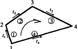
Let's consider generation of the strain compatibility matrix [B]. This matrix for the whole framed structure is obtained by integration of strain compatibility equations of individual statically indeterminable contours. At that, the strain compatibility matrix of the individual contour is obtained from the condition that the algebraic sum of strains in the closed contour is equal to zero (Fig. 2). These strains for an individual bar must be expressed through displacement of nodes [10]. Meant by strains will be such combinations of nodal displacements which, firstly, energetically correspond to generalized forces, i.e. multiplication of strains by forces must be equal to operation of nodal forces in nodal displacements; secondly, they are identically zero at any rigid shift of the bar. Each contour of the structure gives a number of equations of strain compatibility corresponding to the degree of the contour static indetermination.
[image:5.482.176.310.491.575.2]Let's write the equation of strain compatibility in the closed contour (Fig. 2) with sequential connection of bars with the guide unit vectors ti. The degree of contour static indetermination is equal to 3.
e1 e2 e3 e4 0, (14)let's represent (14) as
B
e 0, (15)
eT
e1 e2 e3 e4
0, (16) where [В] – a matrix of contour strain compatibility with a , dimension of (3x12).For the example shown in Fig. 2 the matrix of strain compatibility is given by
B I I I I
, (17)where [I] – a unit matrix with a dimension of (3x3).
Knowing the yield matrix of individual bars and taking into account (14) we can get the matrix of strain compatibility for different statically indeterminable contours. In the actual framed structure containing a lot of contours the matrix of the system strain compatibility consists of the unit lines, each containing a compatibility matrix of the corresponding contour. Peculiarities of the system calculation with a statically determinable contour are given in [9].
Such approach allows formulation of the force method algorithm comparable by complexity and by properties with the finite-element method algorithm. In the contour force method the selection and numeration of independent contours of the framed structure uniquely determine the block structure of the yield matrix []: as soon as the contours are numbered the location of zero and non-zero blocks in the matrix can be specified unambiguously []. But nonuniqueness of this matrix structure remains which is connected with a possibility to select different systems of independent contours in the initial structure. In spatial structures it is more complicated than numeration of nodes and bars for calculation by finite-element method.
2.2 FEM in the form of force method
Let's consider one variant of FEM in the form of force method for calculation of continual systems. It is based on approximation of discontinuous stress fields and application of penalty method [11] for satisfying equilibrium equations. The corresponding variational adjustment with a penalty has a form of complementary energy functional stationarity condition
) E d u L dS A P A P d
(
П T T T T
S T
T 1
2 1
, (18)
where
Let's write the equation of strain compatibility in the closed contour (Fig. 2) with sequential connection of bars with the guide unit vectors ti. The degree of contour static
indetermination is equal to 3.
e1 e2 e3 e4 0, (14)let's represent (14) as
B
e 0, (15)
eT
e1 e2 e3 e4
0, (16) where [В] – a matrix of contour strain compatibility with a , dimension of (3x12).For the example shown in Fig. 2 the matrix of strain compatibility is given by
B I I I I
, (17) where [I] – a unit matrix with a dimension of (3x3).Knowing the yield matrix of individual bars and taking into account (14) we can get the matrix of strain compatibility for different statically indeterminable contours. In the actual framed structure containing a lot of contours the matrix of the system strain compatibility consists of the unit lines, each containing a compatibility matrix of the corresponding contour. Peculiarities of the system calculation with a statically determinable contour are given in [9].
Such approach allows formulation of the force method algorithm comparable by complexity and by properties with the finite-element method algorithm. In the contour force method the selection and numeration of independent contours of the framed structure uniquely determine the block structure of the yield matrix []: as soon as the contours are numbered the location of zero and non-zero blocks in the matrix can be specified unambiguously []. But nonuniqueness of this matrix structure remains which is connected with a possibility to select different systems of independent contours in the initial structure. In spatial structures it is more complicated than numeration of nodes and bars for calculation by finite-element method.
2.2 FEM in the form of force method
Let's consider one variant of FEM in the form of force method for calculation of continual systems. It is based on approximation of discontinuous stress fields and application of penalty method [11] for satisfying equilibrium equations. The corresponding variational adjustment with a penalty has a form of complementary energy functional stationarity condition
) E d u L dS A P A P d
(
П T T T T
S T T 1
2 1
, (18)
where
LT
gs (19)–static boundary conditions in the form of distributed load,
A
T
P
0
(20) –equilibrium equations in the differential form; {} – a stress vector; {u} – a displacement vector; – field; S– contour; {P} – a volumetric force vector; [E] – a flexibility matrix of the generalized Hook's law; [A] – a differential operator; – a penalty characteristics.
Whenusingthevariational formulation in stresses the solution is sought in a multitude of statically admissible stress fields satisfying the static boundary conditions and equilibrium equations.It is necessary to provide existence of piecewise continuous derivatives from stress components. For example, for plane stress problem of the elasticity theory the differentiability of stresses хonly by х, y– only by y, а – and by x, and by y is obligatory.
So, normal stresses can have discontinuities in areas perpendicular to the boundaries of elements. Application of such discontinuous approximations results in a necessity to use special class of finite elements [11, 12].
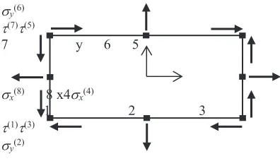
Shown in Fig. 3 is one of simple elements of such type representing a rectangle the four nodes in the tops of which respond to tangent stresses, the two nodes in lateral sides of which respond to normal stresses х , the two nodes in the upper and lower sides respond to y.
Location of nodal points here must satisfy discontinuity conditions for normal stresses.
[image:7.482.191.389.301.415.2]Figure 3. Finite element
Fig. 3. Finite element
Distribution of stresses here is represented by the following polynoms:
x = 1 + 2x; y = 3 + 4y; = 5 + 6x + 7y + 8xy. (21) By applying the approximation data in the equilibrium equations (20) we get
2 + 7 + 8x + px= 0; 4 + 6 + 8y + py = 0. (22)
With the volumetric forces px, py constant by element the conditions (22) can be satisfied
only in case the following condition is identically met:
8x = 8y = 0. (23)
Since this does not ensure exact integration of the penalty summand of a functional (18), it is defined to synthetically decrease the integral calculation accuracy for the given element, which helps vanishing the expression in the integral part of the penalty term.
Whereas the given finite element gives the acceptable accuracy and reproducibility, the deficiencies connected with integration of the penalty summand take place. Determination of nodal functions of forms and flexibility matrix is given in [11].
y(6)
(7)(5)
7 y 6 5
x(8) 8 x4x(4)
1 2 3
(1)(3)
2.3 FEM in the form of force method for calculation of framed structures. Creation of generalized force method equation system
The idea of the generalized force method consists in application of finite-element method in one of two forms: displacement method and force method. At that, determination of unknown values along the bar is carried out analytically with the use of integral expression –
generalized Mohr formula [13] with a matrix of tangent rigidity [2, 3, 13], which is an integral characteristic of the stress-strain state of all points in the bar cross-section. From this the rigidity change is considered. As a result, two hybrid methods for elastic-plastic calculation are obtained. At that, the finite-element method in the form of force method has advantages: there is no necessity in determination of the intermediate rigidity matrix of the bar element, it is possible to immediately proceed with creation of the resolvent equation system.
In order to distinguish two methods let's consider that:
– finite-element method in the form of displacement method with the generalized Mohr method – this is a non-linear hybrid finite-element method;
– finite-element method in the form of force method with the generalized Mohr method –
this is a non-linear generalized force method. Considered in works [2, 3] is a non-linear hybrid finite-element method for elastic-plastic calculation of plane grids. Here the integral function of cross-section state law is used as a tangent rigidity matrix [16, 17].
When using the classical force method [14] the availability of geometrically unchangeable main system is required. Since the finite-element method is a discrete method, there is no necessity in selecting the main system, but equilibrium equations under external force action must be taken into account if stresses are approximated. At that, if the action is in the form of displacements, the equilibrium equations shall be considered through the additional work (24).
Let's consider creation of FEM equations in the form of force method for framed structures. On the basis of the Castigliano variational principle let's write the functional for complete potential energy of the system in stresses [1, 15]
e S
T
T E d u XdS
) (
П 1
2 1
, (24)
where the first member represents the complementary deformation energy from the stress change functions, and the second member represents the force potential in contour S with the given displacements u.
At that, if the external displacements are not specified (u = 0), then expression for complementary energy in the finite-element method will be equal to
E d) (
П T
e
1 2
1
, (25)
But in this case, it is necessary to satisfy the equilibrium equation in order to determine the complete energy [15]. This is taken into account for continual systems with the help of penalty summand [11].
Since the potential energy in the framed structure can be expressed directly through internal forces and moments X, then the external forces P can be theoretically added to a functional for potential strain energy and differentiated, particularly, by approximation coefficients. As a result, a system of resolvent equations of the finite-element method in the form of the force method must be created for calculation of framed structures
2.3 FEM in the form of force method for calculation of framed structures. Creation of generalized force method equation system
The idea of the generalized force method consists in application of finite-element method in one of two forms: displacement method and force method. At that, determination of unknown values along the bar is carried out analytically with the use of integral expression –
generalized Mohr formula [13] with a matrix of tangent rigidity [2, 3, 13], which is an integral characteristic of the stress-strain state of all points in the bar cross-section. From this the rigidity change is considered. As a result, two hybrid methods for elastic-plastic calculation are obtained. At that, the finite-element method in the form of force method has advantages: there is no necessity in determination of the intermediate rigidity matrix of the bar element, it is possible to immediately proceed with creation of the resolvent equation system.
In order to distinguish two methods let's consider that:
– finite-element method in the form of displacement method with the generalized Mohr method – this is a non-linear hybrid finite-element method;
– finite-element method in the form of force method with the generalized Mohr method –
this is a non-linear generalized force method. Considered in works [2, 3] is a non-linear hybrid finite-element method for elastic-plastic calculation of plane grids. Here the integral function of cross-section state law is used as a tangent rigidity matrix [16, 17].
When using the classical force method [14] the availability of geometrically unchangeable main system is required. Since the finite-element method is a discrete method, there is no necessity in selecting the main system, but equilibrium equations under external force action must be taken into account if stresses are approximated. At that, if the action is in the form of displacements, the equilibrium equations shall be considered through the additional work (24).
Let's consider creation of FEM equations in the form of force method for framed structures. On the basis of the Castigliano variational principle let's write the functional for complete potential energy of the system in stresses [1, 15]
e S TT E d u XdS
) (
П 1
2 1
, (24)
where the first member represents the complementary deformation energy from the stress change functions, and the second member represents the force potential in contour S with the given displacements u.
At that, if the external displacements are not specified (u = 0), then expression for complementary energy in the finite-element method will be equal to
E d) ( П T e 1 2 1
, (25)
But in this case, it is necessary to satisfy the equilibrium equation in order to determine the complete energy [15]. This is taken into account for continual systems with the help of penalty summand [11].
Since the potential energy in the framed structure can be expressed directly through internal forces and moments X, then the external forces P can be theoretically added to a functional for potential strain energy and differentiated, particularly, by approximation coefficients. As a result, a system of resolvent equations of the finite-element method in the form of the force method must be created for calculation of framed structures
X P 0, (26)which is similar in appearance to the classical force method, but internally represents the piecewise continuous approximation. With the specified external displacements the system will take the following form
X u . (27) Matrix equations (26) and (27) represent the systems of FEM resolvent equations in the form of force method. It is supposed that no penalty summand in the functional for complete energy must be taken into account for elastic-plastic calculation of the framed structures. The coefficients will be calculated using the generalized Mohr formula [13].3 Conclusion
Simplicity and substantiation of FEM classical scheme based on the minimum potential energy principle retard, in some measure, development of the finite-element formulations supported by the alternative variational principles. Nevertheless, the finite-element method in displacements suffers significant difficulties at resolution of problems with absolutely rigid bars and has an error at determination of stresses, which is important at elastic-plastic calculation.
In particular, FEM in the form of force method based on the Castigliano variational principle makes it possible to avoid such difficulties. Also, at solution of big systems of linear algebraic equations (SLAE) (more than thousand of equations) the important factor is a significant accumulation of rounding errors occurred in the process of a great number of arithmetic operations. In this case it is recommended to use double accuracy of calculations. Application of hybrid methods may lead to decrease in a number of equations, i.e. decrease in computational operations and, correspondingly, to increase in calculation accuracy.
Unlike the classical force method and contour force method a number of unknown values in the system of FEM resolvent equations in the form of force methods will be a little more, but the advantage will consist in simplicity of calculation scheme and equation system creation. Difficulties can be connected with the approximating functions. But since the bar is a one-dimensional continuum, the processes of impact on it (mechanical, thermal) in the most cases are described by relatively simple differential equations.
Thus, application of the proposed hybrid formulations may significantly increase calculation accuracy and speed at determination of elastic-plastic deformations.
References
1. M. Sekulovich, Finite element method (Stroyizdat, Moscow, 1993) 2. V. A. Meleshko, Procedia Structural Integrity, 6 (2017)
3. V. A. Meleshko, U. L. Rutman, Procedia Structural Integrity, 6 (2017)
4. S. P. Timoshenko, J. Gudier, The theory of elasticity (Science Publ., Moscow, 1979) 5. V. P. Ilyin, V. V. Karpov, A. M. Maslennikov, Numerical methods for solution of
structural engineering problems (Higher School Publ., Minsk, 1990)
6. K. Vasidzu, Variation methods in the theory of elasticity and plasticity (Mir, Moscow, 1987)
7. V. V. Lalin, Equations of strain compatibility as a basis for force method algorithmization. Structural mechanics and calculation of structures. Collection of studies (Saint Petersburg, 1992)
9. V. V. Lalin, Equations of strain compatibility for calculation of statically indeterminate trusses by force method. Structural mechanics and calculation of structures. Collection of studies (Saint Petersburg, 1992)
10. T. N. Bugaeva, Algorithmization of structure calculation by force method PhD thesis (Saint Petersburg, 2000)
11. A. A. Lukashevich, Modern numerical methods of structural engineering (KhSTU, Khabarovsk, 2003)
12. Yu. S. Sukhodulova, N. A. Truphanov, PNIPU Bulletin, 1 (2012)
13. V. A. Meleshko, U. L. Rutman, Materials physics and mechanics, 31, 67-70 (2017) 14. A. S. Volmir, Yu. P. Grigoryev, A. I. Stankevich, Structural performance of materials
(Drofa publishing house, Moscow, 2007)
15. A. S. Sakharov, I. Altenbach, Finite element method in mechanics of rigid bodies. (Higher School, Kiev, 1982)