International Journal of Innovative Technology and Exploring Engineering (IJITEE) ISSN: 2278-3075,Volume-8 Issue-6, April 2019
Abstract: In our project study we are going to analyse merits and demerits of various MPPT algorithms. A novel MPPT algorithm will be developed and implemented on a micro grid connected to the utility grid. The novelty of proposed technique will lie in its easy implementation. Performance of the proposed MPPT algorithm will be compared with Perturb & Observe (P&O), Current based MPPT. MATLAB based simulation results will be reported.
Index Terms: Solar System, MPPT, P&O Method, Current Based MPPT.
I. INTRODUCTION
Photovoltaic (PV) energy is currently “considered as one of the most renewable natural energy sources in the world because it is clean, free, abundant, pollution-free and inexhaustible. Due to the rapid growth in solar cells and power electronics technology, PV energy has received increasing interest in electrical power applications.”Nonetheless, the “present energy conservation efficiency of PV array is still low.It requires maximum power point tracking(MPPT) control techniques to extract the maximum power from PV arrays in order to achieve maximum operating efficiency.” “A PV cluster as of now is a nonlinear voltage that fluctuates with exhibit temperature and sun oriented separation, making the most extreme power point(MPP) hard to find. To beat this issue, different techniques, for example, the bother and perception strategy and Incremental conductance strategies,” have been proposed for the MPPT calculations of PV clusters. “In the perturbation and observation method, the operating voltage of PV array changes the duty ratio in order to locate variations in directions for maximising PV array current. If power increases, the operating voltage is further perturbed in the same direction; If it decreases, the direction of the perturbation is reversed. This method does not requires solar panel characteristics, but it remains unsuitable for applications under rapidly changing atmospheric conditions. The disadvantage of perturb and observation method can be minimised by comparing the incremental and instantaneous conductance of PV arrays. This method is more accurate and can provide good performance under rapidly changing
Revised Manuscript Received on April 07, 2019.
B Ramakrishna , Department of EEE, Koneru Lakshmaiah Education
Foundation, Vaddeswaram, AP, India.
T Srikanth , Department of EEE, Koneru Lakshmaiah Education
Foundation, Vaddeswaram, AP, India.
M Naga Chaitanya, Department of EEE, Koneru Lakshmaiah Education Foundation, Vaddeswaram, AP, India.
T Vijay Muni, Department of EEE, Koneru Lakshmaiah Education
Foundation, Vaddeswaram, AP, India.
conditions.” “In this paper, a novel current-based incremental conductance method that produces smooth transition and fast response to the MPP is proposed. The proposed novel current maximum power point tracking (CMPPT)method adjusts currently proportional to the power slope with respect power array current, and provides advantages of smooth and rapid transition to the MPP. In addition that the digital phase locked loop (DPLL),which detects the phase of grid voltage as well as its peak voltage, is addressed.” “A PI controller using d-q transformation is employed for grid current control in the single-phase dc/ac inverter.”Results from analysis, simulation, and hardware implementation of the power conditioning system are”detailed [6-7].
II. REVIEWONMPPTTECHNIQUES The following techniques are some of the widely used MPPT techniques applied on various PV applications . MPPT:
“It is an electronic system that operates the photovoltaic modules in a manner to extract the maximum power from the system.” It is a operating point at which maximum power can be extracted from the system. Usually represented as MPP. “The yield of sun powered module is an element of sun powered irradiance, temperature. For the most part MPPT is introduced in the middle of PV framework and burden. Coupling to the heap for greatest power exchange may require either giving a higher” voltage at lower current or lower voltage at higher current.
III. PERTURB&OBSERVEMETHOD The P&O method is mostly used in MPPT because it has simple structure and required in few parameters. “If perturbs the PV array terminal voltage and compare the PV output power with the perturbation. when the PV power and PV voltage increases at same time perturbation at the step size ,ΔD will added for duty cycle, D to generate the next cycle of perturbation in order to force the operating point moving towards the MPP. When PV power increases and PV voltage decreases and vice versa, the perturb direction step size subtracted for next cycle of the perturbation.” “This process will carried from continuously until MPP is reached. The system will oscillates the around MPP this will result in loss of energy. The oscillations can be minimised by reducing the perturbation step size it has the slow down the MPP tracking system.”
Comparative Analysis of Perturb and Observe
Method and Current Based Method
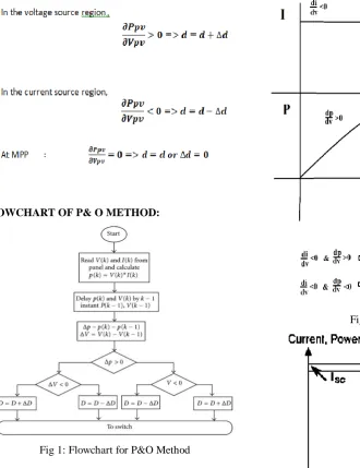
FLOWCHART OF P& O METHOD:
Fig 1: Flowchart for P&O Method
IV. CURRENTBASEDMPPT
“Implementing the perturbation and observation method is simple because it only increases or decreases reference voltage. However, this method cannot readily track any immediate and rapid change in the environment. One alternative is the incremental conductance method”
In the voltage source region:
In the current source region:
Fig 2: I-V & P-V Graphs
CURVE-FITTING TECHNIQUE:
“MPP is the extreme value of the p-v characteristic of a pv panel is predicted in this technique. To anticipate ,this p-v trademark ,pv board can be demonstrated disconnected dependent on scientific conditions or numerical approximations.” To accomplish a precise p-v bend fitting, a third –order polynomial function as
Where the coefficients a, b, c and d are dictated by examining of PV voltage and power in interims. Separation of gives
International Journal of Innovative Technology and Exploring Engineering (IJITEE) ISSN: 2278-3075,Volume-8 Issue-6, April 2019
MPP,
Thus, the voltage at MPP can be calculated as
In this procedure, a,b,c and d are more than once inspected in a range of couple of milliseconds utilizing numerical conditions characterized in the Vmpp is determined.
V. DC/DCBOOSTCONVERTER
[image:3.595.311.550.56.161.2]A boost converter is a DC-to-DC power converter that steps up voltage from its input“to its output.It is a class of switched-mode power supply (SMPS) containing at least two semiconductors and at least one energy storage element: a capacitor, inductor, or the two in combination. To reduce voltage ripple, filters made of capacitors are normally added to such a converter's output and input.”
Fig 3: Schematic diagram of boost converter VI. COMAPARISION BETWEEN PERTURB&OBSERVE AND CURRENT BASED MPPT (A)PERTURB & OBSERVE SIMULATION
DIAGRAM
[image:3.595.48.503.504.715.2]Fig 4: Simulation Circuit with P&O
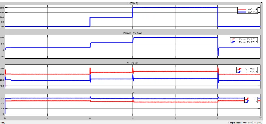
Fig 5: Simulated Results with P&O method
(B)CURRENT BASED MPPT SIMULATION DIAGRAM:
Fig 6: Simulation Circuit with current based MPPT
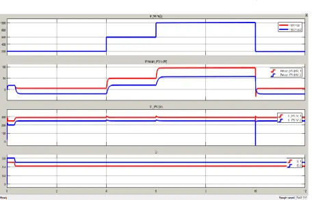
Fig 7: Simulated Results with Current-based MPPT algorithm
IV. CONCLUSION
In this paper the performance of current based method is
[image:4.595.72.529.402.695.2]International Journal of Innovative Technology and Exploring Engineering (IJITEE) ISSN: 2278-3075,Volume-8 Issue-6, April 2019 The perturb& observe method is simple and easily to
implement. Hence the perturb& observe method still stands to be a competent algorithm for tracking maximum power point.
REFERENCES
1. V.Salas, E.olias, A.Barrado, and A.lazaro “Review of the maximum power
point tracking algorithm for stand-alone photovoltaic system.”
2. Y.Chen,K.Smedley,F.Vacher, and J.Brouwer “A new maximum power
point tracking controller.”
3. B.Subudhi and R.Pradhan “Characterstics evaluation and parameter
extraction of a solar array based on experimental analysis.”
4. M.A.S Masoum, H.Dehbonei, and E.F.Fuchs “Theoretical and
experimental analyses of photovoltaic systems with voltage and current based maximum power point tracking.”
5. Sanghoey lee, jae-Eon kim and Hanju cha “Design and Implementation of
photovoltaic power conditioning system using a current-based maximum power point tracking.”
6. T. Vijay Muni, D. Priyanka, S V N L Lalitha, “Fast Acting MPPT
Algorithm for Soft Switching Interleaved Boost Converter for Solar Photovoltaic System”, Journal of Advanced Research in Dynamical & Control Systems, Vol. 10, 09-Special Issue, 2018
7. T Vijay Muni, SVNL Lalitha, B Krishna Suma, B Venkateswaramma, “A
new approach to achieve a fast acting MPPT technique for solar photovoltaic system under fast varying solar radiation”, International Journal of Engineering & Technology, Volume7, Issue 2.20, pp-131-135.
AUTHORSPROFILE
Mr. Naga Chaitanya is working as an Assistant Professor in the Department of EEE, Koneru Lakshmaiah Education Foundation, Vaddeswaram, A.P, India. He received B. Tech degree from JNTU VZM and M. Tech degrees from Andhra University. He is currently pursuing PhD from Andhra University, Visakhapatnam. His research areas include industrial automation and process control, power system protection.
T.Vijay Muni is presently working as Assistant Professor in EEE Dpeartment at Koneru Lakshmaiah Education Foundation, Vaddeswaram, A.P, India.