International Journal of Innovative Technology and Exploring Engineering (IJITEE) ISSN: 2278-3075, Volume-9 Issue-1, November 2019
D.Manish chowdary, R.Karthikeyan
Abstract: MIG welding is used in automotive industries which helps in good opportunity to reduce production costs, decrease vehicle weight and improve the strength of sheet metal joining. In this project, the objective is to study welding parameters used in joining two dissimilar metals. Aluminum 6 series and aluminum 7 series with thickness both 6 mm was weld together using MIG welding with tailor welded blanks method. In this project the voltage(V), wire feed(F) and gas pressure(P) are maintained according to the material used for MIG welding. By using design expert software MIG welding parameters are optimized to obtain good tensile strength. Response surface methodology type is used to optimization to study the parameters of MIG WELDING.
Key Words: Tensile strength, dissimilar metal welding, Metal Inert Gas Welding, aluminum 6-series and 7-series, MIG welding, Response surface methodology
Nomenclature
MIG Metal inert gas welding V Voltage in (volts) F Wire feed (mm/s) P Gas pressure(bars)
I. INTRODUCTION:
Metal inert gas welding (MIG) is a process during which a high voltage arc forms between consumable wire and also the metal pieces those to be welded. during this welding method, the heat is going to be generated through the jumping current of the gap between electrode and also the piece of work metal, inflicting them to soften, and join. A shielding gas feeds through the gun beside the electrode. This shielding gas shields the melting metal from contaminants within the atmosphere air. The parameters are maintained are voltage(V), wire-feed(F) & gas pressure(P). The experiments are done so that the parameters are absorbed and maintained according to the materials used. The study of parameters in MIG welding will helps to know the strength of the joints. The strength of the joint is known by performing the tensile test that is mechanical property of the joints. The filler material used in the MIG welding is according to the type of materials welded. Tensile strength is performed on the universal testing machine.
UTM consists of
Frame: which helps to mount the holders to mount on it.
Load generator: which helps to generate the load in the machine so that the load is generated.
Push buttons: they help to move the holding jaws up and down
Revised Manuscript Received on November 05, 2019.
D. Manish chowdary, Department of Mechanical Engineering, GRIET, Hyderabad, India, Email: [email protected]
DR.R. Karthikeyan,Department of Mechanical Engineering, GRIET, Hyderabad, India, Email: [email protected]
Digital measuring device provides the test result.
Test fixtures, specimen holding jaws are also parts of machine.
The work specimens are placed between the jaws that are loaded on the frame. The jaws help to hold the specimens firmly so that the load can be applied on the specimens. while loading specimens the jaws are moved up and down so that the specimens are adjusted between the jaws. The load is applied gradually on the specimens so that the digital meter shows maximum load that the pieces can hold. The apparatus is shown in fig.1.
FIG.1: UTM machine
II. MIG WELDING MACHINE:
MIG welding may be a welding method within which a high voltage arc formed between a consumable wire electrode and the work pieces, the heat generated between the work pieces and the welding gun will helps to join the work pieces and the welding is done, the shielding gas is provided to the welding gun so that shields welded bed from contaminants from air. the process can be automated and also can be in conventional method. A continuing voltage, Direct current power supply is most ordinarily applied with MIG welding. There are four primary metal transfer in MIG are, those are circular, short-circuiting, spray, and pulsed-spray, every and each kind of metal transfer technique have completely different properties and corresponding benefits and limitations. Originally MIG welding is used for welding metallic element and alternative non-metallic materials within Forties, MIG welding was presently applied to iron as a result of it provides fast weld welding time as compared to conventional welding processes. any developments throughout the Fifties and Sixties gave the method additional skillfulness and as a result, it became a extremely implemented process. MIG welding is that the mostly used conventional welding method, most popular for its flexibility. The machine is shown in fig.
Fig.2: Mig Welding Machine
PARAMETERS:
Parameter could be a amount whose worth is chosen for the actual circumstances and in reference to that different variable quantities could also be expressed. These are the ones which influence the result. The parameters considered in the project MIG welding are:
Welding voltage 1. Wire feed rate 2. Gas flow rate 1.Welding voltage:
Welding voltage is set by the operator according to the material used for welding, voltage plays major role in welding so that the voltage influences the strength of the joint of welding.in this project voltage is varied from experiment to experiment designed based on design expert software. 2.Wire feed rate:
The electrode is consumable in MIG welding. The feed rate mainly effects the deposition on the weld bed. The higher feed rate gives the more deposition of feeder material on the weld bed, which effects the strength of the joint. The wire feed rate can be adjusted by the welding apparatus.
3.Gas flow rate:
In MIG welding gas flow in the torch plays a major role in the welding. The gas from the welding gun helps to form a shield area near the welding so that the weld bed is not exposed to the atmospheric gases. Due to this phenomenon the weld bed will be perfect and good in condition. Gas flow rate can be adjusted the knob placed to the cylinder.
III. EXPERIMENTAL WORK:
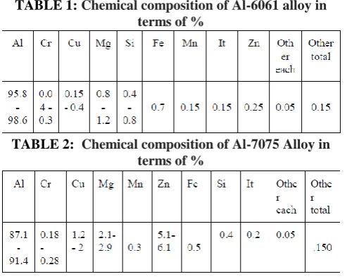
In this project first select the type of optimization to be done. Selection of optimization process is done by using design expert software.by this software we can select the type of optimization. In this project we have selected the Box-Behnkendesign. In this investigation, the metal plates of 6-mm thickness, Al – 6061 and Al – 7075, are welded. The work piece material is cut into required pieces by using hack saw which is electrically powered and the edges are grinded for removing the excess material which gives good welding properties. Composition and properties of the base metals are shown in the tables
.
[image:2.595.305.552.53.251.2][image:2.595.132.212.79.175.2]
TABLE 1: Chemical composition of Al-6061 alloy in terms of %
TABLE 2: Chemical composition of Al-7075 Alloy in terms of %
The base metals are processed into the required dimensions for the welding so that the welding is done properly. The dimensions are shown in figure. the plates of 6mm-thickness are taken and cleaned properly and should make slight groove on one edge of every plate. The groove is made to fill the filler material on the plates while welding to get good welding and mechanical properties. The experiment is done 15 times with different parameters changes according to design of optimization.
Properties Al6061 Al 7075
Modulus of elasticity 74-83 70-85
Relative density 2.6 2.7
Poisson’s Ratio 0.33 0.33
Hardness 35 65
Tensile strength(T)/ Compressive Strength
115(T)
220(T)
TABLE 3: Mechanical Properties of Al6061 and Al7075 Box–Behnken model (BBD) is an independent quadratic form with no embedded factorial or divisional factorial points where the parameter mixtures measure square at the midpoints of the vector space perimeters and midpoints. In the present study, the effects of the three freelance variables welding voltage, wire feed speed and gas pressure were examined through the implementation of the Box–Behnken test model and also the RSM. The application of statistical experimental design techniques in the production and optimization of welding that lead to increased improvements in weld strength. Experiments were established based on a BBD with three factors at three levels and each independent variable are coded at three levels between −1, 0 and +1. The coding of the variables was done by the following equation:
X=F(xi,xz) i = 1, 2, 3, ..., k
Where x is that the dimensional value of an independent variable; Xi is that the real value of a freelance variable; X z is that the real value of a variable
[image:2.595.314.534.372.540.2]International Journal of Innovative Technology and Exploring Engineering (IJITEE) ISSN: 2278-3075, Volume-9 Issue-1, November 2019
[image:3.595.341.511.64.331.2]variation for the dimensional value of the variable i.. The coded values for box-Behnken design are shown in table 4.
Table 4: Coded values for box-Behnken design
S No V F P
1 -1 -1 0
2 1 -1 0
3 -1 1 0
4 1 1 0
5 -1 0 -1
6 1 0 -1
7 -1 0 1
8 1 0 1
9 0 -1 -1
10 0 1 -1
11 0 -1 1
12 0 1 1
13 0 0 0
14 0 0 0
15 0 0 0
In coded values -1, 0, +1 are the intervals that shows how the parameters are maintained for the experiments. -1 represents for the lowest value that can be maintained. +1 represents for the highest value that can maintained.0 represents for the medium value of the parameters. Actual values, that represents the coded values are shown in table 5. The experiments are done according to the actual values. The operator should maintain the values and do the welding properly without any errors. Next step after completion of welding is to know the strength of the joint.to know the strength of the joint we have to know the tensile strength of the joint. Tensile strength can be known by universal testing machine is shown in figure 1. The pieces after welding fig 3, are cut to the required dimensions for the tensile testing.
Table 5: actual coded values
S No V F P V F P
1 -1 -1 0 210 2 8
2 1 -1 0 450 2 8
3 -1 1 0 210 10 8
4 1 1 0 450 10 8
5 -1 0 -1 210 6 6
6 1 0 -1 450 6 6
7 -1 0 1 210 6 10
8 1 0 1 450 6 10
9 0 -1 -1 330 2 6
10 0 1 -1 330 10 6
11 0 -1 1 330 2 10
12 0 1 1 330 10 10
13 0 0 0 330 6 8
14 0 0 0 330 6 8
[image:3.595.67.270.88.295.2]15 0 0 0 330 6 8
Fig 4: welded specimens
The welded pieces are cut into required dimensions by using wire cutting. Wire cutting is proper method for cutting the welded pieces.Fig 5 shows the testing specimens.
FIG 5: Testing specimens for tensile strength
Table 6: Tensile strength for the experiments:
S No V F P V F P TS
1 -1 -1 0 210 2 8 6.03
2 1 -1 0 450 2 8 8.83
3 -1 1 0 210 10 8 7.35
4 1 1 0 450 10 8 8.61
5 -1 0 -1 210 6 6 6.21
6 1 0 -1 450 6 6 8.18
7 -1 0 1 210 6 10 7.47
8 1 0 1 450 6 10 9.15
9 0 -1 -1 330 2 6 7.92
10 0 1 -1 330 10 6 7.66
11 0 -1 1 330 2 10 8.08
12 0 1 1 330 10 10 9.11
13 0 0 0 330 6 8 9.20
14 0 0 0 330 6 8 9.03
15
0 0 0
330 6 8
9.08 Developing an empirical relationship
[image:3.595.308.545.393.680.2] [image:3.595.56.283.467.759.2]Y= 1/4f(x1,x2,x3……….xk)
The second-order quadratic (regression) equation used to represent the response surface Y is given b
Y 1⁄4 b0 b1x1 b2x2 b3x3 b11x12 b22x22 b33x23 b12x1x2 b13x1x3 b23x2x2 b13x1x3 b23x2x3 b13x1x3 b23x2x3 b23 x2x3
T where b0 is the average response and b1, b2, b3 square measure regression coefficients based on various linear, interaction, and square factor terms. The constant value was measured using expert software design method. The significance of each constant determined by the student's t-test and p-values; the square measure given in Table 6. "Prob > F" but 0.0500 values mean that the square calculation of model terms is important. V, F, P, V2, F2, and P2 test critical template terms in this case. Values above 0.10 imply that the terms of the model are not significant. The findings for the second-order surface response model with multiple regression coefficients. the ultimate empirical relationship was created using only these coefficients, and also the developed final empirical relationship is given below:
TS=-11.20422+
V+F+P+V*F+V*P+F*P+V^2+P^2+P^2 kN
TS=-11.20422+0.057389+0.36000+1.82448-(8.02083E-004 ) -(3.020083E-004)+0.040312 kN
[image:4.595.320.524.158.369.2]Variance analysis (ANOVA) technique was used to testing the adequacy of the empirical relationship established. The level of trust stated during this investigation was considered to be 95 percent. The relationship is also considered adequate if the calculated value of the F quantitative relationship of the model developed does not exceed the quality tabulated value of the F magnitude relationship and the calculated value of the R quantitative relationship of the relationship developed should exceed the quality tabulated value of the R magnitude relationship for the desired confidence level. The design has been found to be satisfactory. the lack of fit F worth of 3.61 implies that the lack of fit is insignificant. Shown on fig 6.
FIG 6:
The layout of an experiment unit, the development of a mathematical model, the study of the optimal combination of input parameters and the diagrammatic representation of values. In order to obtain the influencing nature and optimized state of the system on TS, surface plots and contour plots that calculate square indications of achievable variable independence were established for the expected empirical
and 3 x-and y-axis parameters. Such contours of response should promote every area of the experiment within the prediction of the response (TS). The answer plot apex reveals as much TS as possible.A contour plot is created to visually show the area with the greatest strength. Such a plot will be additionally complicated for second-order responses compared to the simple sequence of parallel lines that may occur with first-order models.
IV. CONCLUSIONS:
1. To predict the tensile strength of MIG welded aluminum alloy joints using welding parameters at a confidence level of 95 percent, an empirical relationship was established. 2. Under the welding conditions of the welding voltage V=329.2, wire feed frequency F=8.67, gas pressure P=9.19 3, a peak tensile strength is obtained at a load of 9.32 kN. 3. Of the 3 process parameters investigated, the gas rate of flow and welding voltage and wire feed rate equally plays major role within the welding method.
International Journal of Innovative Technology and Exploring Engineering (IJITEE) ISSN: 2278-3075, Volume-9 Issue-1, November 2019
REFERENCES:
1. Rakesh Kumar1* and Gurinder Singh Brar(PhD Candidate,
IKGPTU, Kapurthala) Department of Mechanical Engineering, North West Institutions Group, Dhudike (Moga)-142001, Punjab, India. Mechanical Engineering Department, Guru Nanak Dev Engineering
College, Ludhiana, Punjab, India-141006. Corresponding
author-e-mail address: hod [email protected] Box, G. E. P., & D.
W. (1960). Some recent three-level models for quantitative variables
analysis. Engineering, 2, 455–475.
2. Chen, W., Huang, Y., Qi, J., Tang, M., Zheng, Y., Zhao, and others
(2012). Optimizing the extraction of phenolic compounds from areca
husk aided by ultrasound. Food Treatment and Conservation Paper, http:/dx.doi.org/10.1111/j.1745-4549.2012.00748.x
3. Dawson, P. L., & Dawson, R. R. (1998). Use surface reaction analysis to maximize the performance of the whole egg of ultrapasteurized water. Science of poultry, 77, 468–474.
4. Box–Behnken development and surface response methodology to model some Turkish coals N. Aslan*, Department of Engineering CebeciMining, University of Cumhuriyet, 58140 Sivas, Turkey Received on 21 February 2006; received in revised form on 1 June 2006
AUTHORSPROFILES
D.Manishchowdary has completed engineering from GITAM university Hyderabad Telangana during 2013-2017 with 2nd class. B.Tech project was on “Temperature distribution in friction stir welding of joining two dissimilar aluminum materials” Presently pursing masters in Design for manufacturing at GRIET, Participated in some of the major conferences conducted by institute of engineering (India).
Dr R. Karthikeyan, Professor of GRIET has