DESIGN AND DEVELOPMENT OF AN INTELLIGENT WIRELESS EMBEDDED SYSTEM
LIM YEE HWAI
This Report is Submitted in Partial Fulfilment of Requirements for The Bachelor Degree of Electronic Engineering (Computer Engineering)
Faculty of Electronic and Computer Engineering Universiti Teknikal Malaysia Melaka
vi
Dedicated to my beloved family, for your love and supports.
vii
ACKNOWLEDGEMENT
First and Foremost, I would like to express my sincere gratitude to my supervisor Dr. Wong Yan Chiew for her guidance, support and comment on the project. Her counsel and help during this project is important to me. Her guidance and support make my final year project can be done on time and successfully. Besides that, she also willing to take some of her time to listen the problems that I had meet in this project.
Besides that, I would like to thank to my fellow friends for their encouragement, commands on different aspects, and support on this project. Their commands make me have different ideas by considering on other aspects and field in order to completing this project.
viii
ABSTRACT
ix
ABSTRAK
x
TABLE OF CONTENTS
CONTENT PAGE
TITLE i
STATUS VERIFICATION FORM ii
STUDENT DECLARATION iii
SUPERVISOR DECLARATION iv
DEDICATION v
ACKNOWLEDGMENT vi
ABSTRACT vii
ABSTRAK viii
TABLE OF CONTENTS ix
LIST OF FIGURES xi
LIST OF TABLES xiii
LIST OF APPENDIX xv
LIST OF ABBREVIATIONS xvi
CHAPTER 1 ... 1
1.1 Project Background ... 1
1.2 Problem Statement ... 2
1.3 Objective ... 2
1.4 Scope ... 3
1.5 Thesis Structure ... 3
xi
2.1 Introduction ... 5
2.2 Basic working principle ... 10
2.3 Rectifiers ... 11
2.4 Transmitter ... 13
2.5 Receiver... 15
2.6 Wireless Power bank ... 18
2.7 Summary ... 18
CHAPTER 3 ... 19
3.1 Introduction ... 19
3.2 Work Flow ... 19
3.3 Block Diagram ... 20
3.4 Hardware Development ... 22
3.5 Summary ... 24
CHAPTER 4 ... 25
4.1 Introduction ... 25
4.2 Development Process ... 25
4.3 Result ... 29
4.3.1 Simulation Circuit from AC Power Supply to Power Bank ... 29
4.3.2 Simulation Circuit from Power Bank to Mobile Device ... 31
4.3.3 AC Power Supply to Power Bank ... 33
4.3.4 Power bank to Mobile Device ... 44
4.4 Project Cost ... 49
4.5 Discussion ... 50
4.6 Conclusion ... 51
CHAPTER 5 ... 52
5.1 Conclusion ... 52
5.2 Recommendation... 52
REFERENCES ... 54
APPENDIX I ... 57
xii
LIST OF FIGURES
Figure 2.1: Nikola Tesla and the Wardenclyffe tower ... 6
Figure 2.2: Operation between the transmitter and receiver ... 10
Figure 2.3: Half-wave rectification circuit ... 11
Figure 2.4: Full-wave rectification circuit ... 11
Figure 2.5: Transmitter... 13
Figure 2.6: Transmitter coil with circuit board ... 13
Figure 2.7: Receiver ... 15
Figure 2.8: IOS receiver and Android Receiver... 15
Figure 3.1: Flow chart of the project ... 20
Figure 3.2: Block diagram from AC power supply to power bank ... 21
Figure 3.3: Block diagram from power bank to mobile device ... 21
Figure 3.4: Acrylic sheet ... 22
Figure 3.5 Hex Cap Screw ... 22
Figure 3.6 Recessed Rubber Feet ... 23
Figure 3.7 Floor-Mounted Drilling Machine ... 23
Figure 3.8 Sewing supplies with threads ... 24
Figure 4.1 Voltage of transmitter coil ... 26
Figure 4.2 Connection of input power and ground ... 26
Figure 4.3 Transparent Acrylic sheet with four holes at the corner ... 27
Figure 4.4 Base station transmitter... 27
Figure 4.5 Connection of port ... 28
Figure 4.6 Wireless charging bag... 28
Figure 4.7 Schematic Diagram from AC power supply to Power bank ... 29
Figure 4.8 Transient Graph from AC power supply ... 30
xiii
Figure 4.10 Schematic Diagram from Power Bank to Mobile Device ... 31
Figure 4.11 Transient Graph from Power Bank ... 32
Figure 4.12 Transient Graph from Mobile Device... 32
Figure 4.13 Illustration distance between transmitter coil and receiver coil ... 35
Figure 4.14 Power of transmitter and receiver versus distance between transmitter and receiver ... 36
Figure 4.15 Peak voltage of transmitter at different distance between transmitter and receiver versus time... 37
Figure 4.16 Peak voltage of receiver at different distance between transmitter and receiver versus time... 38
Figure 4.17 Frequency of transmitter and receiver versus distance between transmitter and receiver. ... 39
Figure 4.19 Graph Voltage against distance between transmitter and receiver ... 45
Figure 4.20 a) Iphone device and b) Android Device ... 47
xiv
LIST OF TABLES
Table 2.1: Comparison between Inductive Charging, Resonance Charging and
Microwave Charging ... 8
Table 2.2: Comparison of advantages and disadvantages for inductive charging, resonance charging and microwave charging ... 9
Table 2.3: Comparison in terms of calculation between half-wave and full-wave rectifier ... 12
Table 2.4: Comparison between different types of transmitter ... 14
Table 2.5: Comparison between receiver for IOS and Android... 16
Table 2.6: Comparison between Mini USB and Micro USB ... 17
Table 2.7: Comparison between different types of receiver ... 17
Table 2.8: Comparison between wireless power bank ... 18
Table 4.1 Coil alignment of transmitter and the range and sensitivity of transmission ... 34
Table 4.2 Value of distance between transmitter and receiver, power of transmitter and receiver ... 36
Table 4.3 Relationship of distance between transmitter and receiver and the frequency of transmitter and receiver ... 39
Table 4.4 Condition of transmitter that affect the graph in oscilloscope ... 41
Table 4.5 Time to charge up the power bank by wired or wireless and the percentage of battery in power bank ... 42
Table 4.6 Distance between transmitter and receiver and the voltage and efficiency of charging ... 44
Table 4.7 Position of Mobile Device and the status level of battery ... 46
Table 4.7 Time to charge up two types of smartphone and the percentage of battery... 48
xv
LIST OF APPENDIX
Appendix No. Title Page
xvi
LIST OF ABBREVIATIONS
AC Alternating Current
DC Direct Current
1
CHAPTER 1
INTRODUCTION
In this chapter, we are explaining about the details of the project which is design and development of an intelligent wireless embedded system. Besides that, we also explained the background, problem statement, scope and chapter organization of this project.
1.1 Project Background
An embedded system is designed to perform a specific function which it is consists of computer software and hardware. Since the embedded system only performs a certain function, thus the embedded system usually is small size and cheap in order to increase its performance [1][2]. Wireless handsets such as mobile phones are one of the examples of embedded system have become part and parcel in our life. It is the fastest and the easiest medium of communication amongst people. However, it brings some advantages as well as disadvantages. The lifespan of mobile phone’s battery has always a problem for the users. Cables are required for power transmission between power outlets and mobile phones [3]. In order to solve this kind of problem, inductive charging method is introduced to charge up the Smartphone.
2
power supply and receiver is installing the devices [5]. This inductive charging system is electrically safe, waterproof and low maintenance. However, they have a weakness which is they consume more power that leads to more heat is generated, low efficiency, and the high cost of construction due to their complex circuit [6].
This project is to design and develop a wireless power system for charging a mobile phone and illustrate how magnetic induction is used to transfer the energy wirelessly. This wireless power system will be implementing inside a bag for the worker.
1.2 Problem Statement
Nowadays, users have more than one handheld device which resulting collection of bulky chargers. However, charging the device when away from the plug has turned into frustration for peoples. This is due to the device requires power outlets with wires. It is inconvenient for users to charge multiple devices with lots of wires whenever they go. Wireless inductive charging system has brought convenient for users to charge portable devices wirelessly. The wireless power transmission was done by applying the concept of magnetic induction. The aim of this project is to design and develop a wireless power system for charging a mobile phone and illustrate how magnetic induction is used to transfer the energy wirelessly.
1.3 Objective
1. To design a wireless charging system that can use to charge the mobile phone 2. To modify a wireless charging system into a customize compartment
3
1.4 Scope
Knowledge in electromagnetic induction is applied in the induction charging method. Transmitter and receiver are used in order to perform inductive charging. For making all the mobile phone can using this application, two different types of receiver were use, which is IOS and Android. For users to charge up their mobile phone at anytime and anywhere, there is a power storage have to be install inside the bag. In order to allow the mobile phone to charge automatically, the power bank is installed with a voltage controller, so that it will charging up once its power is lower than the threshold voltage and disable to charging when it passes the certain voltage. A prototype will be developed for the wireless charging system.
There are some parts not including in this project which increases the performance of wireless charging as efficient as contact with the wires and speed up the wireless charging. The cost of the applications also depends on the power storage, which means a higher power storage will costly the prototypes.
1.5 Thesis Structure
This thesis will include five main chapters which are an introduction, literature review, methodology, result and discussion and the conclusion and recommendations. Generally, chapter one will introduce the project background, objectives, problem statements, scopes of the project and the thesis structure.
Chapter 2 is describing the literature review of the project. We explained about every topology of components from the previous journal or articles which are related to the development of this project. Besides this, comparisons between the components have been included in this chapter.
4
Chapter 4 is the result and discussion for this project. All the results obtained from both hardware and software will be observed and recorded. Besides that, the output obtained from the experimental is comparing with the theoretical result.
5
CHAPTER 2
LITERATURE REVIEW
In this chapter, the comparison between different types of method charging, such as inductive charging, resonance charging and microwave charging are discussed. The required transmitter, receiver, power bank required is compared based on their properties and prices.
2.1 Introduction
6
Figure 2.1: Nikola Tesla and the Wardenclyffe tower
The wireless charging can be dividing into two major fields, which is near field and far field. The near field wireless charging method consists of inductive charging and resonance charging where areas the far field consists of the microwave charging [8]. These three types method of charging have different ways to operate as well as their specification.
Inductive charging used to transfer energy between two objects by using an electromagnetic field. Energy sent from the charging station through an inductive coupling to an electrical device [9]. This enables batteries of the mobile phone to be charge or the device to operate. The primary coils and the secondary coils in proximity combine to form an electrical transformer.
Resonance charging method is used for charging the device or items that required a large amount of power, such as an electrical car, laptop, or vacuum cleaner. In order to transfer the energy from one point to another point, both coils must be tuned into the same electromagnetic frequency.
7
message signal is transmitted through an antenna called slotted wave guide antenna. Then the receiver in the mobile phone will convert the microwave into power to charge the phone [10] [11]. The comparison between Inductive Charging, Resonance Charging and Microwave Charging are shows in Table 2.1.
8
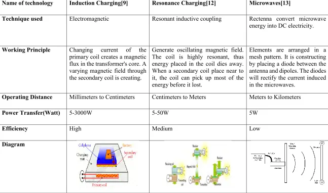
Table 2.1: Comparison between Inductive Charging, Resonance Charging and Microwave Charging Name of technology Induction Charging[9] Resonance Charging[12] Microwaves[13]
Technique used Electromagnetic Resonant inductive coupling Rectenna convert microwave energy into DC electricity.
Working Principle Changing current of the primary coil creates a magnetic flux in the transformer's core. A varying magnetic field through the secondary coil is creating.
Generate oscillating magnetic field. The coil is highly resonant, thus energy placed in the coil dies away. When a secondary coil place near to it, the coil can pick up most of the energy before it lost.
Elements are arranged in a mesh pattern. It is constructing by placing a diode between the antenna and dipoles. The diodes will rectify the current induced in the microwaves.
Operating Distance Millimeters to Centimeters Centimeters to Meters Meters to Kilometers
Power Transfer(Watt) 5-3000W 5-50W 5W
Efficiency High Medium Low
9
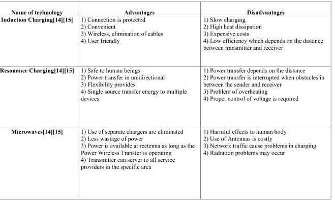
Table 2.2: Comparison of advantages and disadvantages for inductive charging, resonance charging and microwave charging
Name of technology Advantages Disadvantages
Induction Charging[14][15] 1) Connection is protected 2) Convenient
3) Wireless, elimination of cables 4) User friendly
1) Slow charging 2) High heat dissipation 3) Expensive costs
4) Low efficiency which depends on the distance between transmitter and receiver
Resonance Charging[14][15] 1) Safe to human beings
2) Power transfer in unidirectional 3) Flexibility provides
4) Single source transfer energy to multiple devices
1) Power transfer depends on the distance
2) Power transfer is interrupted when obstacles in between the sender and receiver
3) Problem of overheating
4) Proper control of voltage is required
Microwaves[14][15] 1) Use of separate chargers are eliminated 2) Less wastage of power
3) Power is available at rectenna as long as the Power Wireless Transfer is operating
4) Transmitter can server to all service providers in the specific area
1) Harmful effects to human body 2) Use of Antennas is costly