PERFORMANCE ANALYSIS ON MULTIPHASE VOLTAGE SOURCE INVERTER
Mohd Hafizzudin bin Ismail
Bachelor of Power Electronic and Drives
PERFORMANCE ANALYSIS ON MULTIPHASE VOLTAGE SOURCE INVERTER
MOHD HAFIZZUDIN BIN ISMAIL
A report submitte in partial fulfillment of the requirements for the degree of Power Electronic and Drives
Faculty of Electrical Engineering
SUPERVISOR DECLARATION
“I hereby declare that I have read through this report entitle “Performance Analysis On Multiphase Voltage Source Inverter” and found that it has comply the partial fulfillment for awarding the degree of Bachelor of Electrical Engineering (Power Electronics and drives)”
Signature : ...
Supervisor‟s Name : DR AUZANI BIN JIDIN
STUDENT DECLARATION
“I declare that this report entitle “Performance Analysis On Multiphase Voltage Source Inverter” is the result of my own research except as cited in the references. The report has not been accepted for my any degree and is not concurrently submitted in the candidature of any other degree”
Signature : ...
Student‟s Name : MOHD HAFIZZUDIN BIN ISMAIL
DEDICATION
Especially dedication is to my beloved mother Puan Hamimah bt Abdul Majid, my beloved father En Ismail bin Hassan, my sister and brothers beloved
For taking care of me and educating me all these while. Also thank for their continuous prayers until I became what I‟m now.
Also for my family Dr Auzani Bin Jidin
Thank you very much
And not forgetting to all my relatives
Especially Electrical Engineering (Power Electronics and Drives) batch 2009-2012 The success belongs to us all
ACKNOWLEDGEMENT
Assalamualaikum……
ABSTRACT
ABSTRAK
TABLE OF CONTANT
CHAPTER TITLE PAGE
SUPERVISOR DECLARATION DECLARATION
DEDICATION
ACKNOWLEDGEMENT ii
ABSTRACT iii
ABSTRAK iv
TABLE OF CONTENTS v
LIST OF FIGURE ix
LIST OF TABLE xii
1 INTRODUCTION
1.1 Project Background 1
1.2 Problem Statement 3
1.3 Objective 4
CHAPTER TITLE PAGE 2 LITERATURE REVIEW
2.1 Introduction 5
2.2 Generalized Sinusoidal PWM With Harmonic Injection 5
For Multi-Phase VSIs
2.3 Modeling Of Multiphase Voltage Source Inverter 6
2.4 Realization Of A Spwm Inverter For Multiphase 7 8 Induction Motor Drive
2.5 Theory Of 3-Phase And 5-Phase System 8
2.6 Sinusoidal Pulse Width Modulation(SPWM) 9
3 METHODOLOGY
3.1 Introduction 11
3.2 Project Methodology 11
3.3 FYP2 Flowchart 13
3.4 Project Phase 14
CHAPTER TITLE PAGE
4 DESCRIPTION OF THE EXPERIMENTAL SET-UP
4.1 Introduction 16
4.2 Ezdsp F28335 Digital Signal Processor (DSP)-Board 17
4.3 Altera Complex Programmable Logic Devices (CPLD) 19
4.4 Gate Drivers 21
4.5 Interface Circuit 23
4.6 Voltage Source Inverter 24
5 RESULTS
5.1 Introduction 25
5.2 Simulation Result 25
5.2.1 Spwm Waveform For 3 Phase And 5 Phase 25 Voltage Source Inverter
5.2.2 3 Phases And 5 Phase Voltage Source 26
Inverter In Matlab/Simulink
5.2.3 Generating SPWM In Matlab/Simulink Software 28 5.2.4 Current And Voltage For 3 Phase And 5 Phase 30
CHAPTER TITLE PAGE
5 5.3 Hardware Results 35
5.3.1 Current Ripple For 3-Phase VSI And 35 5-Phase VSI
5.3.2 Voltage And Current From Different 36 Frequency Of Switching
6 ANALYSIS AND DISCUSSION
6.1 Introduction 40
6.2 Analysis 40
6.3 Discussion 44
7 CONCLUSION AND RECOMMENDATION
7.1 Introduction 45
7.2 Conclusion 45
7.3 Recommendation 46
REFERENCES 47
LIST OF FIGURES
FIGURE TITLE PAGE
2.1 Three Phase System 10
2.2 Five Phase System 10
2.3 Basic Principles Of PWM 12
3.1 Flowchart Of The FYP2 15
3.2 Project Development 18
4.1 Complete Drive System 19
4.2 DS1102 Digital Signal Processor (DSP)-Board 20
4.3 Output Signal From Ezdsp 21
4.4 Altera FPGA 22
4.5 Output Signal From FPGA 23
4.6 Gate Drivers Circuit 24
4.7 Output Signal From Gate Driver Circuit 25
4.8 Interface Circuit 26
4.9 Output Signal From Interface Circuit 26
FIGURE TITLE PAGE
5.1 3-Phase SPWM 29
5.2 5-Phase SPWM 29
5.3 3-Phase VSI Simulation Block Diagram 29
5.4 5-Phase VSI Simulation Block Diagram 30
5.5 3-Phase Voltage Source Inverter Connection 30
5.6 5-Phase Voltage Source Inverter Connection 31
5.7 Simulation Using IQ-MATH 31
5.8 SPWM For 5-Phase Inverter In Simulation 32
5.9 SPWM For 3-Phase Inverter In Simulation 32
5.10 Phase Voltage For 5-Phase Multiphase Voltage Source Inverter 33 (Voltage Versus Time)
5.11 Phase Voltage For Three Phase Voltage Source Inverter 34 (Voltage Versus Time)
5.12 Total Harmonic Distortion For 3-Phase Voltage 35
5.13 Total Harmonic Distortion For 5-Phase Voltage 35
5.14 Total Harmonic Distortion For 3-Phase Current 36
5.15 Total Harmonic Distortion For 5- Phase Current 37
5.16 3-Phase Current For Hardware 38
5.17 5-Phase Current For Hardware 39
5.18 SPWM For 3-Phase VSI 40
FIGURE TITLE PAGE
5.20 Voltage And Current Output For 2KHz 41
5.21 Voltage And Current Output For 3KHz 41
5.22 Voltage And Current Output For 4KHz 41
6.1 Intersection Point For 3-Phase Inverter 44
6.2 Intersection Point For 5-Phase Inverter 44
6.3 Effect Of PWM To Current Ripple For 3-Phase Inverter 45
6.4 Effect Of PWM To Current Ripple For 5-Phase Inverter 45
6.5 Output Voltage For 3-Phase Inverter 46
LIST OF TABLE
TABLE TITLE PAGE
CHAPTER 1
INTRODUCTION
1.1 Project Background.
The electric motor is important to our lives. Many machinery uses an electric motor in it operation no matter on high operation, medium operation and low operation. Nowadays, many motors use an inverter to convert the DC voltage and enter the inverter to convert the DC voltage into an AC source and supply to the motor. An inverter, the switching of the motor is to make the AC motor run with AC source. For this project, the multilevel voltage source inverter is used to run the motor. From the previous study, multilevel inverter has many advantages on voltage/current ripple, total harmonic distortion (THD) and low power dissipation on power switches. The important thing on multilevel inverter is a the switching scheme. Sinusoidal Pulse Width Modulation (SPWM) is chosen to make the switching scheme for this multilevel inverter.
(ASDs), uninterruptible power supplies (UPS), static var compensators, active filters, flexible AC transmission systems (FACTS), and voltage compensators, which are only a few applications. For sinusoidal AC outputs, the magnitude, frequency, and phase should be controllable.
According to the type of ac output waveform, these topologies can be considered as voltage source inverters (VSIs), where the independently controlled AC output is a voltage waveform. These structures are the most widely used because they naturally behave as voltage sources as required by many industrial applications, such as adjustable speed drives (ASDs), which are the most popular application of inverters. Similarly, these topologies can be found as current source inverters (CSIs), where the independently controlled ac output is a current waveform. These structures are still widely used in medium-voltage industrial applications, where high-quality voltage waveforms are required. Static power converters, specifically inverters, are constructed from power switches and the ac output waveforms are therefore made up of discrete values. This leads to the generation of waveforms that feature fast transitions rather than smooth ones.
For instance, the ac output voltage produced by the VSI of a standard ASD is a three-level waveform. Although this waveform is not sinusoidal as expected, its fundamental component behaves as such. This behavior should be ensured by a modulating technique that controls the amount of time and the sequence used to switch the power valves on and off. The modulating techniques most used are the carrier-based technique (e.g. sinusoidal pulse width modulation, SPWM), the space-vector (SV) technique, and the selective-harmonic-elimination (SHE) technique.
inverter. Variable number of pulse width modulation systems are used to generate a variable voltage and frequency.
1.2 Problem Statement.
Many types of inverter nowadays only changing the DC source to a 3 phase system and to the load. In this project, dc source will be converted into five phase AC source and supply to the load. In this modern world, many researchers make a researcher on making a new inverter like a multiphase source inverter using the additional phase like a 5 phase voltage source inverter. If the motor runs with 3 phase source, it becomes normal but if 1 of the 3 phase supply broken, motor will run with unbalance load. After a few times the motor will trip because the motor overheating. Researcher gets an idea to make a multiphase voltage source inverter to run an induction motor because when motor using multiphase voltage source inverter, the motor also can run if 1 phase of the source broken. In this project, the 5 phase RL load will drive with 5 phase voltage source inverter. It will show what will effect to the load voltage and current when increasing the phase to the load and voltage source inverter.
1.3 Objective
The main objective of the project is
1) To analyze the performance of multilevel inverter in term of current ripple and total harmonic distortion (THD).
2) To construct the switching scheme of the multiphase inverter using a
Matlab/Simulink and Ezdsp.
1.4 Scope
In order to achieve this objective, several scopes had been outlined.
i. Matlab/Simulink software and Ezdsp software will be performed on
computer and also Ezdsp platform device is used.
ii. The switching sinusoidal pulse width modulation (SPWM) for the multiphase
inverter were programed in Matlab/Simulink software.
iii. The difference between 3 phase and multiphase inverter were simulated in Matlab/Simulink.
CHAPTER 2
LITERATURE REVIEW
2.1 Introduction
This chapter will discuss overall of the previous research about this project and what is the opinion from previous research can use for this project. In this chapter also will discuss about the theory of 3 phase and 5 phase system.
2.2 Generalized Sinusoidal PWM With Harmonic Injection For Multi-Phase Vsis
research based on motor controller. In space vector modulation, the voltage reference is a most important because that kind of reference is use to make decision on vector choosing. Multiphase voltage source inverter also have a problem when running a motor and that is called low order voltage harmonic, this kind of harmonic will make the stator current harmonic increase [1].
That is why the switching for multiphase inverter always different and keep on researching. When a multiphase inverter supplied with a sinusoidal PWM switching, we must mind that the output of the voltage source inverter do not have a low order stator harmonic [1]. The sinusoidal pulse width modulation and space vector modulation become a famous technique on control the speed of ac motor.
2.3 Modelling Of Multiphase Voltage Source Inverter
Power circuit of multiphase voltage inverter is shown in figure above and the dc link input is considered constant. For figure above, the load will connect with star connection. The multiphase inverter is simulated in vector transformation and the voltage drop is neglected. When a space vector modulation apply on multiphase voltage inverter, each sector represented with a d and q transformation just like x and y axis on three phase inverter. Generally, number of vector for multiphase voltage source inverter represented
n
2 . Thus, for a five phase voltage source inverter, there have 32 vector including 2 zero vector [2]. The important thing on multiphase inverter, the pairing of the switching device must ON or OFF for one time. Second things must be remind, the rms voltage output must same with a d and q for a reference voltage for a space vector modulation technique.
make a high on harmonic on output voltage for multiphase voltage inverter [2]. So, this two technique is apply to make the output voltage of voltage source inverter similarly like a sinusoidal in addition to make a switching scheme for a multiphase voltage source inverter. However, output voltage of voltage source inverter cannot be produce 100% because the switching of gate make a losses for the system.
2.4 Realization Of A Spwm Inverter For Multiphase Induction Motor Drive
Conventionalthree phase motor usually use a three phase source from a three phase voltage source inverter. Development on many type of power converter make a new idea to develop a converter that have more than three phase. Example of advantage of multiphase power converter is a produce a high voltage from a low DC source. For a decade researching is make to settle a problem that occurred in high voltage application. For a multiphase inverter, there a many type of switching technique can be apply for an example sinusoidal pulse width modulation and space vector modulation. The objective for all studied on multiphase voltage inverter is to generate a output voltage of inverter similarly sinusoidal wave and increasing the performance on total harmonic distortion (THD). Today, the multiphase inverter become more popular when the inverter come out with many advantage on performance of the load that the inverter drive [3]. The multiphase voltage source inverter have 25% improvement on produce a sinusoidal output voltage [3]. For 3 phase inverter drive, the space vector is a popular technique, but when space vector and sine PWM applied on multiphase inverter, the result almost same on all parameter like a voltage output, total harmonic distortion.
voltage source inverter. For a 360 plane, 512 of vector becomes a problem on divide a
degree for each vector [3]. Many problem will occurred when space vector applied on multiphase voltage source inverter especially on complexity of space vector algorithm. When a inverter changing on phase, the old space vector algorithm cannot be use and new algorithm must create. For SPWM, the switching algorithm cannot be a problem when the inverter phase is changing. The original algorithm can be use when a inverter phase is changing [3]. SPWM technique is most easy technique to generate a PWM.
2.5 Theory Of 3 Phase And 5 Phase System
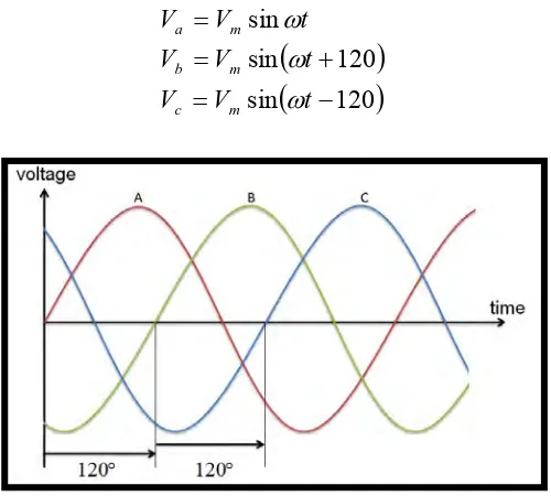
Five phase system is not much different than a three phase system. Theoretically, a five phase system differ only in term of phase with other phases. Phase shift of five phase system was 72 degree and 120 degree for three phase system. This difference will be more clearly seen when the process to produce a sinusoidal pulse width modulation (SPWM) in which each phase in the system will be contrasted with a triangular wave. For three phase system, this process will be easier because the phase difference is large. Figure below shows SPWM for three phase and five phase that have been simulated in matlab/simulink software. For a 3 phase system, this instantaneous voltage is followed.
120
[image:24.595.199.449.493.718.2]sin 120 sin sin t V V t V V t V V m c m b m a