Article:
Ruddle, R.A., Savage, J.C.D. and Jones, D.M. (2003) Levels of control during a
collaborative carrying task. Presence: Teleoperators & Virtual Environments, 12 (2). pp.
140-155. ISSN 1054-7460
https://doi.org/10.1162/105474603321640914
[email protected] https://eprints.whiterose.ac.uk/ Reuse
See Attached
Takedown
If you consider content in White Rose Research Online to be in breach of UK law, please notify us by
University of Leeds, UK
Justin C. D. Savage Dylan M. Jones
School of Psychology Cardiff University, UK
Presence,Vol. 12, No. 2, April 2003,140 –155
©2003 by the Massachusetts Institute of Technology
Abstract
Three experiments investigated the effect of implementing low-level aspects of mo-tor control for a collaborative carrying task within a VE interface, leaving participants free to devote their cognitive resources to the higher-level components of the task. In the task, participants collaborated with an autonomous virtual human in an im-mersive virtual environment (VE) to carry an object along a predefined path. In experiment 1, participants took up to three times longer to perform the task with a conventional VE interface, in which they had to explicitly coordinate their hand and body movements, than with an interface that controlled the low-level tasks of grasping and holding onto the virtual object. Experiments 2 and 3 extended the study to include the task of carrying an object along a path that contained obstacles to movement. By allowing participants’ virtual arms to stretch slightly, the interface software was able to take over some aspects of obstacle avoidance (another low-level task), and this led to further significant reductions in the time that participants took to perform the carrying task. Improvements in performance also occurred when participants used a tethered viewpoint to control their movements because they could see their immediate surroundings in the VEs. This latter finding demon-strates the superiority of a tethered view perspective to a conventional, human’s-eye perspective for this type of task.
1 Introduction
A key characteristic of skilled behavior is that it is executed with various degrees of control by the cognitive system. Some activities require deliberate (or “controlled behavior”) by which is meant moment-to-moment monitoring and adjustment; others require little conscious intervention and may be “run off” in an automatic fashion (or “automatized behavior”) with little need for conscious feedback in the governance of the progress of the skill. Typically, in a complex environment there is an interplay of automatic and controlled pro-cesses that can be envisioned as a hierarchy of control; at the highest level are those activities that involve planning, involving the strategic deployment of attention and effort, while at the lower level are quasi-autonomous activities, typically highly overlearned behaviors (that is, learned to an asymptotic level of achievement and thereafter executed repeatedly). There is by now ample evi-dence for this position, as this scenario has been observed both as individuals develop skills from infancy onwards and in the deployment of skills in complex settings. (See Broadbent, 1977, for a discussion.)
During a person’s everyday life in the real world, certain activities such as walking and grasping objects are generally delegated to the lower levels of
trol (Craik, 1966). Automation of these activities is pos-sible due, in part, to the flexibility with which we can move and the sensory feedback that we obtain. In VEs, however, feedback is of lower fidelity, and some impor-tant sensory information (such as sound and haptics) is often completely missing, so it follows that more com-ponents of a task will require a high level of cognitive control. This provides an opportunity for algorithms that take over the lower-level components of a task to be implemented in a VE’s interface software.
This paper uses the task of two people carrying a long pole to investigate the effects of different levels of con-trol. Three experiments were performed to compare a conventional interface with interfaces in which the low-level operations of grasping an object, holding an ob-ject, and avoiding obstacles were performed by software. First, however, the background to the study is explained in more detail.
2 Two-Person Carrying
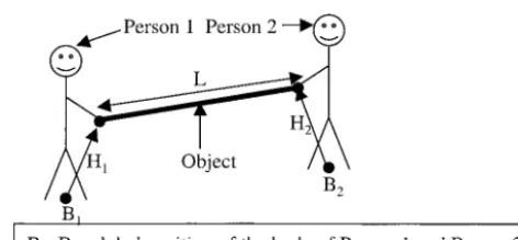
Two-person carrying is an example of a task in which people interact in a collaborative, rather than competitive, manner (Ferrand & Guiard, 1995). The people work towards an agreed goal, the expectation of which can be supported by verbal communication en route. If we consider the constraints of the real world, several factors become evident. First, the task becomes one of two people moving through the environment while connected by a rigid link (the object). Second, if we assume that each person grasps the object at a partic-ular position (for instance, at one end of the object), then the degrees of freedom (DOFs) that are involved may be simplified to those for the global position and orientation of each person’s body and the position and orientation of their hands relative to their body. The distance between the hands of one person and those of the other participant equals the length of the object (the rigid link criterion; see figure 1). Third, people typically carry an object by holding it in a comfortable position (such as to expend the minimum physical effort). Fourth, the movements that the people make can be divided into those that take place at two different levels
of control. At a high level are the movements that are concerned with the general direction and speed of travel, whereas at a low level are the small adjustments in body and hand position that are required to satisfy the rigid link criterion and to maneuver around obsta-cles. These small adjustments are automatic and may take place without deliberate attention in response to forces transmitted through the object and visual infor-mation about the environment and the other person’s movements.
It is perfectly possible to design and build a VE in which users can collaborate to carry a virtual object. In immersive environments, there is a one-to-one corre-spondence between the physical and virtual movements of a user’s hands relative to their body, so interaction in this respect can be considered to be “natural.” How-ever, problems arise in keeping hold of a virtual object that is simultaneously being manipulated by another user, and in negotiating any obstacles that lie along the path that the users are traveling. The application of dual levels of control to these two problems is outlined in the following sections.
2.1 Grasping Virtual Objects
When carrying or manipulating an object in a VE, the range of movements involved can be quite large, occupying the volume of a 2⫻2⫻2 m cube that is cen-tered on each user. Current devices (such as the
[image:3.630.317.553.92.201.2]ToM), although suitable for some collaborative tasks (Basdogan, Srinivasan, & Slater, 2000), are not able to provide haptic feedback over a large volume. In a carry-ing task, this means that users are not able to feel forces “transmitted” though a virtual object and, instead, have to rely solely on visual feedback to coordinate their hand and body movements and to maintain the rigid link criterion.
We consider two options for the design of a carrying interface, the first of which is a conventional VE inter-face. With this, the users can move the virtual pole only when they are both “holding” it, which means that the users’ virtual hands must lie within some tolerance of the pole so that the rigid link criterion is satisfied. If the separation between the users’ hands is either too large or too small, then the criterion is not satisfied, and, in effect, the pole is no longer being carried jointly by the users and movement has to be (momentarily) disal-lowed. Movement recommences when the criterion is next satisfied. With this conventional type of interface, the users have to devote significant attentional resources to maintaining the rigid link criterion, meaning that this aspect of their motor behavior involves a much higher level of control than it does in the real world.
The second option uses a simple software algorithm to emulate the two levels of control. Low-level compo-nents of the task are controlled by the user interface software, leaving the users to perform high-level con-trol, as in the real world. For a carrying task, the algo-rithm works as follows. The intention of a user to carry an object becomes known as soon as they grasp it. Simi-larly, if two users grasp the object, collaborative interac-tion can be inferred until one of the users makes an in-put to release the object. When the users are
collaborating, the interface software maintains the rigid link criterion by making small adjustments in the users’ hand (or body) positions, leaving the users free to de-vote the majority of their attention to the high-level task of traveling through the environment.
2.2 Collisions with Obstacles
A complication arises when collaborative carrying has to be performed in an environment that contains
obstacles. In the real world, obstacle avoidance of this nature is usually trivial but, in VEs, such avoidance takes a great deal of time and attention, even when users are operating on their own (Ruddle & Jones, 2001). Of course, collision response algorithms can be imple-mented that automatically guide users around obstacles (Jacobson & Lewis, 1997; Xiao & Hubbold, 1998), but a difficulty arises from the fact that the process of guid-ance involves software-controlled modifications to the position of a user’s virtual body. In collaborative carry-ing, guidance of one user around an obstacle may actu-ally move the other user to a colliding position whereas, previously, they were collision free. Thus, automatic obstacle avoidance is not wholly compatible with situa-tions in which the movements of one user affects those of another. This leads to a further potential enhance-ment for the low-level capability of the interface software.
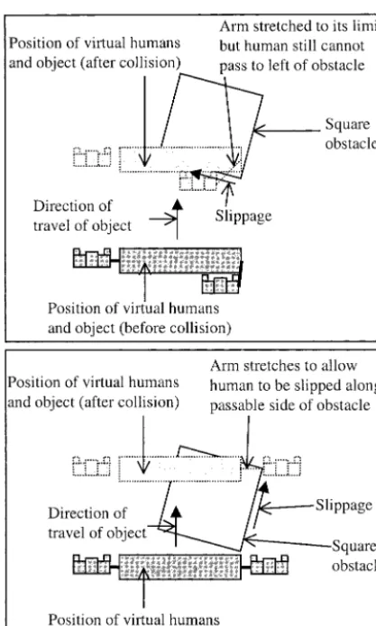
however, always help a user get around an obstacle in a collaborative VE. (See figure 2.) If the obstacle is small then it is passable on both sides, but, if it is large, the direction in which the users are traveling will dictate the sides on which the obstacle is passable. This can lead to the first user being guided by the VE software along an impassable side, either forcing them to retrace their steps or the second user to adjust their path.
2.3 View Perspectives
The preceding portion of this paper dealt with the motor components of two low-level tasks: grasping an object and obstacle avoidance. However, both of these are affected by limitations a user has in their view of a VE, and that view is dictated by the angular field of view (FOV), the position (origin) of the view, and the mech-anism used to vary the view’s position and orientation. Immersive VEs are usually viewed from a first person (“human’s-eye”) perspective, but the impoverished FOV of most head-mounted displays (HMDs) places a severe restriction on how much of the virtual human’s immediate surroundings can then be seen in a single view. For example, the Virtual Research VR4 has a 48⫻36 deg. FOV, which is a typical specification for an HMD but corresponds to a window of only 0.62⫻0.45 m at arm’s length (0.7 m). This is smaller than many objects that people carry and, for collaborative carrying, is particularly restricting because it prevents one user from simultaneously seeing both their virtual hands and the virtual body of the other user.
One solution to this problem is to make the VE’s geometric (graphical) FOV substantially greater than that of the HMD’s optics. However, although this has been performed in some experimental studies (Ruddle, Payne, & Jones, 1999), the distortion that is an inevita-ble consequence carries with it the risk of increasing the incidence of VE sickness, and, even when sickness is not manifest, for safety’s sake user immersion should be fol-lowed by a period of readjustment for visuo-motor co-ordination. A second solution is for a user to adopt an “over the shoulder” (tethered) view perspective, which allows a user to see their immediate surroundings in the VE at the expense of the detail of any object they may be holding in their hands. Such tethered views have been implemented in a number of VE systems (Hind-marsh, Fraser, Heath, Benford, & Greenhalgh, 2000) but not, to our knowledge, with an HMD. Addition-ally, there is also no published research on the effects of tethered versus human’s-eye view perspectives with any type of VE display.
[image:5.630.62.271.92.440.2]Evidence that has a bearing on the issue of view per-spectives comes from some quite different domains of
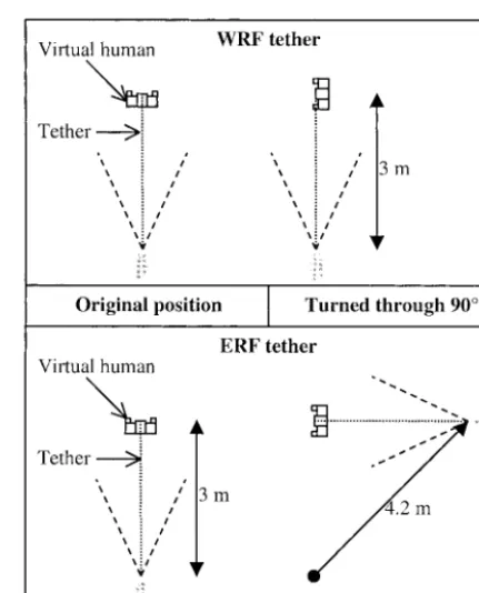
application, namely geographical navigation, submarine warfare, and aviation (Aretz, 1991; Hooper & Coury, 1994; Levine, Marchon, & Hanley, 1984; Wickens & Prevett, 1995). Here the various view perspectives are divided into those that use an ego-referenced frame (ERF) and those that use a world-referenced frame (WRF; see figure 3). At one extreme is the view people have of an environment from their own eyepoint (a hu-man’s-eye view), and at the other is the constant orien-tation, plan view perspective used in north-up maps. In between are tethered views, which can adopt either ref-erence frame. The factor that distinguishes between ERF and WRF perspectives is the orientation that is used; the former are constant relative to the viewer, but the latter are constant relative to the environment as a whole. This means that, if a WRF tether is attached to a virtual human, the view position does not change when the human turns around, but with an ERF tether the view position changes considerably. (See figure 4.)
ERFs are more effective than WRFs for local guidance tasks (such as choosing a direction of travel at a junc-tion) (Wickens & Prevett, 1995) because the orienta-tion of the display is the same as that of the user (the mapping of left and right is consistent). It follows that an ERF tether is likely to be more effective than a WRF tether for the control of a virtual human. Another con-sideration is that the amount of a VE that is visible at a virtual human’s position increases with the length of the tether, but, with an ERF tether, this also magnifies any jitter in the tether position that is produced by
uninten-tional changes in the ERF’s orientation. The main cause of this is sensor noise: 1 deg. of jitter causes a 50 mm change in the position of a 3 m tether, and leads to vi-sual discomfort and eye strain.
3 Experimental Outline
The following experiments investigated the effects of controlling some low-level aspects of motor behavior from within a VE’s interface software. Conceptually, the task used in the experiments involved two people carry-ing a long pole, although for experimental purposes the role of the second person was taken by an autonomous virtual human. Experiment 1 compared a conventional interface, in which participants had to perform both the low- and high-level aspects of control themselves, with an interface in which the software took over the
[image:6.630.312.528.90.357.2]low-Figure 3. Ego- and world-referenced view perspectives.
[image:6.630.60.214.96.228.2]level components of grasping and retaining a hold on the pole. Experiment 2 introduced obstacles to the path along which participants had to carry the pole. Two in-terfaces (rigid arm and elastic arm) were compared. Both of these automated grasping and holding, but the elastic arm interface also facilitated obstacle avoidance. Experiment 3 compared the same two interfaces as ex-periment 2, but using a tethered view perspective. It was predicted across all three experiments that increases in the amount of low-level control performed by the interface would lead to a reduction in the time partici-pants took to perform the carrying task. However, no a priori predictions could be made about the magnitude of the differences. Interest in experiment 3 centered on the usability of a tethered view perspective, which has never before been assessed in an immersive VE.
4 Experiment 1
Each participant performed the task using three interfaces. Two of these were conventional VE inter-faces in which participants had to retain their grasp by keeping their virtual hand within a certain tolerance of the end of the pole. One of these interfaces used a small (75 mm) tolerance, and the other used a large (225 mm) tolerance. With both, error feedback was provided using rubberbanding, which gave the impression that a participant’s hand was stuck to the object using weak glue. In combination, these conditions are referred to as sticky-smallandsticky-large,respectively. With the third interface, the participant’s hand was permanently and inelasticallyattachedto the object by the VE software. For videos of all three conditions, visit http:// www.comp.leeds.ac.uk/royr/video/.
4.1 Method
4.1.1 Participants. Twelve participants (three men and nine women) took part in the experiment, and their ages ranged from 20 to 31. All the participants volunteered for the experiment and were paid an hono-rarium for their participation.
4.1.2 Materials. The VE software was a C⫹⫹
Performer application that was designed and pro-grammed by the authors and ran on a SGI Maximum IMPACT workstation. A Virtual Research VR4 HMD was used, and head-tracking was performed using a Pol-hemus FASTRAK sensor and the MR Toolkit. Images were displayed in stereo in the HMD, and the interpu-pilary distance was adjusted for each participant. The application update rate was 12.5 Hz and, given that the peripherals and graphics ran on the same, single-processor workstation, overall latency was approximately 80 ms.
The VE contained a textured floor, the path to be followed (a line), the virtual human (a 50th percentile man), the object, a 0.2 m radius cylinder (the pant’s body), and a hand (a 3D model of the partici-pant’s right hand; the left hand was not shown). The object was 2 m in length, had a square cross section (75⫻75 mm), and was gray. It was rigidly attached to the virtual human and carried at a height of 1.1 m above the floor.
Participants followed the same path in every trial. This was 31 m in length, contained 60, 90, and 120 deg. right and left turns, and defined the route taken by the virtual human. (It moved as if it were on rails.) This ensured that each participant carried the object along the same path. At each left turn, the virtual human piv-oted while the participant moved, and at each right turn it was the opposite way around. Figure 5 shows a gen-eral view of the VE, with the path and one of the sets of obstacles used in experiments 2 and 3.
participants had to pivot. A slight visual inconsistency was that the VE showed only participants’ right hands although they physically held the box in both hands, which helped make movements of the box (hence the virtual hand) more precise and lessened fatigue when compared with one-handed interaction.
The attached hand interface worked as shown in fig-ure 6. The magnitude of the movement that was al-lowed to take place in each frame was determined as follows. First, the raw movement that participants made with their right hand was calculated as the sum of the movements of their body through the VE and of the box (hand) sensor relative to the HMD sensor. The magnitude and direction of the resultant (allowed) movement were then calculated from the dot product of the raw hand movement and the direction of the ob-ject’s path. The participants’ right hands always re-mained attached to the end of the object. Their body cylinder was moved by the algorithm so that spatial rela-tionship between their virtual body and hands was the same as in the real world (that is, compatibility of physi-cal and virtual movement was maintained).
[image:8.630.321.525.90.230.2]In the sticky hand conditions, movement was calcu-lated and portrayed as follows. The raw movement of a participant’s right hand was calculated in the same way as for the attached hand condition. If this lay within the tolerance (small or large) of any point along the path that was taken by the participant’s end of the object, the object was moved to that position and the rubberband-ing lines were displayed. (See figure 7.) These “con-nected” the participant’s hand to the object and stretched, as if made of strands of glue, when the hand moved. If the participant’s hand was always within toler-ance, the lines were permanently visible. If the partici-pant’s hand lay outside the tolerance, the object did not move and the lines were hidden. During pilot testing, a modification was made to the algorithm to improve its usability. If the object did not move in a frame, all translationary movements of the participant’s body were also disallowed, but rotational movements were permit-ted. The exception to this was if the body translations were towards the participant’s end of the object, in which case participants were moved using a rapid con-trolled movement algorithm (Mackinlay, Card, & Rob-ertson, 1990). The overall effect of this modification was that the participants were prevented from uninten-tionally wandering away from the object but were able to reposition themselves relative to the end at which they grasped it.
[image:8.630.60.300.91.277.2]Figure 5. Scene inside one of the VEs used in the experiments. Visible are the path, the virtual human, the object, a participant’s virtual body (the white cylinder) and right hand (on the extreme right of the horizontal object), and a set of circular obstacles (the gray cylinders). The obstacles were present only in experiments 2 and 3. In experiments 1 and 2, a participant’s viewpoint was vertically above their virtual body, giving the view shown in figures 7 and 12.
4.1.3 Procedure. Participants were run individu-ally and took approximately 1.5 hr. to complete the ex-periment. After this, symptoms of VE sickness were monitored using the Short Symptom Checklist (SSC; Cobb, Nichols, Ramsey, & Wilson, 1999). For all three experiments only minor symptoms occurred, so these data are not reported here.
The experimenter first demonstrated how the at-tached hand interface worked using a plan view, and then a within-VE (human’s-eye) perspective. Then they demonstrated the sticky-large and sticky-small interfaces using the within-VE perspective. Following that, the participant performed seven trials (three practice trials and four test trials) with each of the three interfaces. The practice trials were performed in order of increasing difficulty (attached, sticky-large, and then sticky-small interface). After all three interfaces had been practiced, the participant performed the test trials, with the order in which the interfaces were used balanced using a Latin Square design.
Trials were expected to be completed quickest with the attached hand interface and slowest with the sticky-small interface. However, the primary purpose of the study was to determine the magnitude of the hypothe-sized performance difference.
4.2 Results
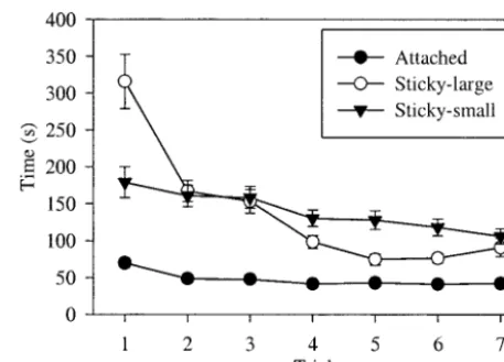
For all of the results, interactions are reported only if they were significant. Effects of learning were investi-gated by analyzing participants’ time data in the practice and test trials separately for each interface. Analyses of variance (ANOVAs) that treated the trial number as a repeated measure showed there were learning effects for the attached,F(6, 11)⫽14.53,p⬍.01, sticky-large, F(6, 11)⫽28.57,p⬍.01, and sticky-small interface, F(6, 11)⫽4.86,p⬍.01. (See figure 8.) The first prac-tice session with the sticky-large interface took a particu-larly long time to complete because this was always the first time that participants had used either of the sticky interfaces.
The remainder of the data that are reported here are for the test trials (trials 4 through 7). The mean time that participants took to complete the test trials was di-vided into the time taken for each type of path segment (straight, left turn (the virtual human pivoted), or right turn (participants pivoted)) and analyzed separately us-ing repeated measures ANOVAs. There were effects of interface for straight segments,F(2, 11)⫽59.74,p⬍
.01, segments when the virtual human pivoted,F(2, 11)⫽27.34,p⬍.01, and when participants pivoted, F(2, 11)⫽20.90,p⬍.01. (See figure 9.)
The time data show that participants took much longer to complete trials when they used the sticky
[image:9.630.61.300.92.277.2]in-Figure 7. The sticky hand interface used in experiment 1, showing the rubberbanding lines that indicate the participant’s hand is within the tracking tolerance of the end of the object.
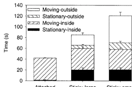
[image:9.630.314.543.93.257.2]terfaces than when they used the attach hand. To inves-tigate this difference, we divided the time taken in each trial into periods when participants were stationary (not attempting to translate) or moving, and periods when their hand was inside or outside the rigid link criterion tolerance from the object. With the attached interface, participants’ hand was classified as always being inside the tolerance because the algorithm kept it attached to the object. The time taken in each period is shown in figure 10. A repeated measures ANOVA showed that participants spent significantly less time stationary with the attached hand interface than with the other two in-terfaces,F(2, 11)⫽2.63,p⬍.01. Participants’ hands were outside the tolerance for less time in the sticky-large condition than in the sticky-small for both periods when participants were attempting to move,F(1, 11)⫽
77.58,p⬍.01, and when they were intentionally sta-tionary,F(1, 11)⫽4.93,p⬍.05.
Finally, the mean angles between participants’ bodies and the path were calculated to give an indication of the efficiency of their body movements in the three interface conditions. Movements were most efficient when this angle was 0 deg. (participants moved tangential to the path). This was performed separately for straight seg-ments and for segseg-ments where the virtual human piv-oted and analyzed using a two-factor, repeated measures ANOVA. (Segments where the participant pivoted were
excluded because no body movements were required.) The analysis showed main effects of interface,F(2, 11)⫽7.86,p⬍.01, and segment,F(2, 11)⫽10.61, p⬍.01. The means for the straight segments and seg-ments where the virtual human pivoted were 20 and 29 deg. (attached), 38 and 42 deg. (sticky-large), and 31 and 37 deg. (sticky-small).
4.3 Discussion
In effect, the attached hand algorithm took over the low levels of control that were involved in perform-ing the carryperform-ing task and allowed participants to main-tain their grasps on the virtual object without conscious effort. In terms of efficiency in human performance, the superiority of this to the sticky-hand interfaces was dra-matic. Participants learned very quickly and moved along the path with an efficiency of more than 90% (cos(a)⫽0.925, whereawas the mean angle between their body and the path). By contrast, participants took twice as long to complete the trials with the sticky-large interface and almost three times as long with the sticky-small interface. The differences between the interfaces were significant for all three types of path segment, but grew in magnitude with increases in the complexity of movements that participants had to make along the path (stationary versus straight line versus curved).
[image:10.630.317.548.93.246.2]Analysis of the time that participants spent stationary
[image:10.630.60.290.93.251.2]Figure 9. Mean time spent in each type of path segment during the test trials (experiment 1). Error bars indicate SE.
and moving, and inside and outside the algorithm toler-ance, shows what participants were attempting to do during the time that caused the difference between the interfaces. With both sticky algorithms, participants spent a substantial amount of time stationary, and this caused most of the difference between the sticky-large and attached hand algorithms. Almost all of the addi-tional difference between the small and sticky-large algorithms took place when participants were at-tempting to move but had their hand in a position that was outside of the tolerance.
This experiment showed the very substantial benefit that accrued from building some simple intelligence into the interface software, even though only a simple carrying task was being performed. The remaining ex-periments in this article used a more difficult carrying task, with obstacles placed along the path, to further investigate the implementation of low-level control al-gorithms in interface software.
5 Experiment 2
Experiment 2 investigated the rigid and elastic arm variants of low-level control. (See subsection 2.2.) With both variants, participants’ right hands were per-manently attached to the end of the object, as for the attached hand condition of experiment 1. With the elas-tic arm variant, parelas-ticipants were guided around the ob-stacles by the VE software. Two different types of VE were used, one containing small, circular obstacles (0.2 m radius) and the other containing larger obstacles that had a square (1.1⫻1.1 m) cross section. The path that participants followed was arranged so that each square obstacle was passable only on one side. For illustrative videos, see the web site mentioned in section 4.
5.1 Method
5.1.1 Participants. Twelve participants (five men and seven women) took part in the experiment, and their ages ranged from 17 to 35. All the participants volunteered for the experiment and were paid an
hono-rarium for their participation. None had taken part in experiment 1.
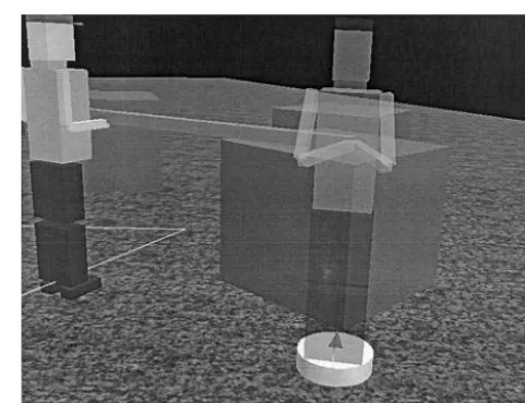
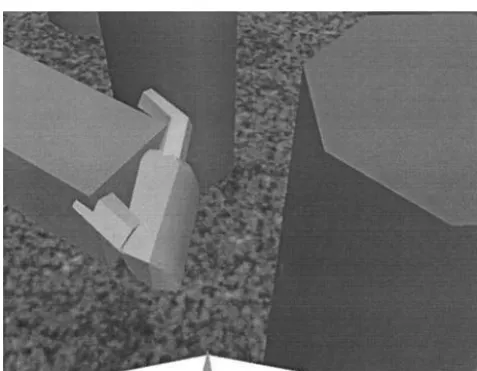
5.1.2 Materials. The same hardware and soft-ware was used as in experiment 1. The VEs were identi-cal to the one used in experiment 1, except for the addi-tion of the obstacles. Ten different sets of the square obstacles were created. Figure 11 shows an example of one of these, viewed using the tethered perspective of experiment 3. The orientations of the obstacles were different in each set, meaning that the sequence of pass-able sides (right or left) also differed. In each trial of the square condition, one of the sets was chosen at random. The circular obstacles were passable on both sides, so only one set was created. (See the earlier figure 5.) Par-ticipants’ actual (that is, human’s-eye) view of this VE is shown in figure 12.
[image:11.630.312.553.91.276.2]The physical interface (three FASTRAK sensors and the box) was identical to experiment 1. When a partici-pant was not in collision with an obstacle, the rigid and elastic arm interfaces both worked in the same way as the attached hand interface of experiment 1. When the
participant collided with an obstacle, the interfaces worked in different ways. With the rigid arm interface, the participant could continue moving only if the body was moved to a noncolliding position. As their hand was attached to the end of the object by the interface algorithm, the easiest way of continuing was to move a hand towards the obstacle, causing the body to move in the opposite direction, a technique that was easily mastered.
The elastic arm interface automatically slipped the participant around the obstacle by allowing the compo-nent of participants’ movement that was tangential to the surface of the obstacle to take place. Thus, partici-pants would be unable to move only if they attempted to travel perpendicularly into an obstacle. The slip algo-rithm was well suited to the simple geometry of the ob-stacles used in the experiment, but a force field algo-rithm would be more appropriate for complex shapes because it helps prevent users from becoming “trapped” in concave regions (Xiao & Hubbold, 1998). To ac-commodate the slippage, participant’s right arms were allowed to stretch, and, once the obstacle had been passed, returned to its physically compatible position
using a rapid controlled movement algorithm (Mackin-lay et al., 1990). The amount of permissible stretch was limited, preventing any participant from moving their virtual right hand more than 0.674 m from the center of their body. (This is the arm length of a 50th percen-tile man; Kroemer, 1987). With this limit, the partici-pant could pass on either side of the circular obstacles but on only one side of the square obstacles. The pass-able side differed from obstacle to obstacle (see previ-ously) and was dictated by the position and orientation of each square obstacle relative to the path that the par-ticipant had to follow. (The autonomous human was constrained to a fixed path, and moved as if it were on rails, thereby constraining the movements of the partici-pants’ virtual human.) If the participant tried to pass on the “wrong” side of a square obstacle, they were slipped around the obstacle until the elastic limit was reached; the participant then had to turn around and backtrack to the passable side of the obstacle. Thus, the two VEs exemplified situations in which arm elasticity was always helpful and where it was, potentially, counterproductive.
5.1.3 Procedure. Participants were run individu-ally and took approximately 1.5 hr. to complete the ex-periment. After this, and as a precautionary measure, symptoms of VE sickness were monitored for 1 hr., us-ing the SSC.
The experimenter first demonstrated how the two interfaces worked and the problems that could occur when obstacles were being negotiated. Next, a partici-pant practiced using one interface in one type of VE (for example, rigid arm and the circular obstacles) and then completed four carrying trials. Then they per-formed the practice and trials with the other type of ob-stacles, and then they used the other interface (for ex-ample, elastic arm) to perform the practice and trials with both types of obstacle. The orders in which partici-pants used the two interfaces and, within each interface, the two types of obstacle were counterbalanced. Partici-pants performed fewer trials with each interface than in experiment 1 because in that experiment the attached hand interface required little training.
[image:12.630.61.300.92.277.2]Two hypotheses were proposed. With the circular obstacles, trials were expected to be quickest with the
elastic arm interface. However, with the square obsta-cles, participants’ performance with the elastic arm was predicted to deteriorate relative to the rigid arm inter-face because they would sometimes be guided around the wrong side of obstacles.
5.2 Results
The data were analyzed using similar types of ANOVA to experiment 1. Effects of learning were in-vestigated by analyzing participants’ time data separately for each combination of interface and obstacle. Re-peated measures ANOVAs showed there were learning effects for the rigid-circular,F(3, 11)⫽902.48,
p⬍.01, and elastic-square conditions,F(3, 11)⫽3.49, p⬍.05, but not for the rigid-square,F(3, 11)⫽1.80, p⬎.05, and elastic-circular conditions,F(3, 11)⫽
0.53,p⬎.05. (See figure 13.)
Inspection of the time data showed that most of par-ticipants’ learning occurred during the first two trials. The remainder of the data that are reported here are the mean data for the remaining trials (trials 3 and 4). The data were analyzed using two-factor (interface⫻ obsta-cle) repeated measures ANOVAs.
Analysis of the mean time that participants took to complete the trials showed main effects of interface, F(1, 11)⫽7.82,p⬍.05, and obstacle,F(1, 11)⫽
9.64,p⬍.05, and there was also a significant interac-tion,F(1, 11)⫽28.91,p⬍.01. (See figure 14.) As before, the mean time was then divided into the time taken for each type of path segment and analyzed sepa-rately. For the straight segments, there were effects of interface,F(1, 11)⫽3.92,p⬍.05, and obstacle,F(1, 11)⫽10.61,p⬍.01, and a significant interaction,F(1, 11)⫽15.03,p⬍.01. For segments when the virtual human pivoted, there was an effect of interface,F(1, 11)
⫽16.31,p⬍.01, but not of obstacle,F(1, 11)⫽0.04, p⬎.05. However, there was a significant interaction, F(1, 11)⫽20.97,p⬍.01. There were no obstacles positioned at the points where participants pivoted, and the time taken for this part of the path was similar in all four conditions. Figure 15 shows the data for all three types of segment.
Differences in the time participants took to perform the trials in each condition could be caused by the effi-ciency of their movement or the time they spent in colli-sion with the obstacles. The former was measured by the angle between the participants’ bodies and the path, and an ANOVA showed a main effect of interface,F(1, 11)⫽8.51,p⬍.05, but not of obstacle,F(1, 11)⫽
4.17,p⬎.05. (See figure 16.)
[image:13.630.60.297.89.259.2]Analysis of the time that participants spent in collision showed a main effect of interface,F(1, 11)⫽11.01, p⬍.01, but not of obstacle,F(1, 11)⬍0.01,p⬎.05.
[image:13.630.315.535.95.246.2]Figure 13. Mean trial time during experiment 2. Error bars indicate SE.
However, there was a significant interaction,F(1, 11)⫽
34.81,p⬍.01. (See figure 17.) With both interfaces, 41% of the collision time was spent colliding with the impassable side of the square obstacles.
5.3 Discussion
As predicted, the elastic arm produced a substan-tial time advantage (60%) over the rigid arm with the small (circular) obstacles. With the former, participants only had to travel in their general intended direction
and the collision response algorithm negotiated the ob-stacles for them. With the latter, participants had to ex-pend a substantial amount of time and attention on the task of obstacle avoidance, and it was this that ac-counted for the time difference between the two inter-faces. With the square (partly impassable) obstacles, par-ticipants’ performance was similar with the two
interfaces. In other words, and again as predicted, if we compare the square obstacles with the circular obstacles, performance with the elastic arm decreased relative to the attached hand. The elastic arm algorithm took over more of the low-level tasks from the participants than did the rigid arm algorithm and, overall, the elastic arm was clearly superior.
[image:14.630.61.286.90.258.2]There was, however, considerable room for improve-ment. The minimum time in which a participant could complete a trial was 39 sec. (The path was approximately 39 m long, and the maximum speed of movement was 1.0 m/sec.) Even in the most efficient condition (elastic-circu-lar) participants took 38% longer than this, and in all three of the other conditions participants took at least double the minimum time. A prime cause of this is likely to have been the impoverished FOV, which made it difficult for participants to see where they should travel to negotiate the obstacles. A solution is to use a tethered view perspec-tive, because this would let participants see more of a vir-tual human’s immediate surroundings. To investigate this,
[image:14.630.314.535.93.248.2]Figure 15. Mean time spent in each type of path segment during the post-learning trials of experiment 2. Error bars indicate SE.
Figure 16. Mean angle between participants’ virtual body and the path in the post-learning trials with human’s-eye (experiment 2) and tethered view perspectives (experiment 3). Error bars indicate SE.
[image:14.630.61.286.323.473.2]experiment 3 repeated experiment 2 but with a tethered view perspective. In all other respects, the two experiments were identical.
6 Experiment 3 6.1 Method
6.1.1 Participants. Twelve participants (five men and seven women) took part in the experiment, and their ages ranged from 20 to 28. All the participants volunteered for the experiment and were paid an hono-rarium for their participation. None had taken part in the other experiments.
6.1.2 Materials and Procedure. The experi-ment used the same hardware, software, interface de-vice, and VEs as experiment 2. Compared with experi-ment 2, the only difference in the content of the VEs was that the participants’ virtual body cylinders and hands were replaced by a transparent model of another virtual human. (See figure 11.) Participants viewed the VE from a 3 m ERF tether that was attached to the transparent virtual human. (For videos, see the afore-mentioned web site.) The direction of the tethered view was the same as the direction of movement of this vir-tual human, as measured by a participant’s waist sensor. (The origin of the tether was 3 m behind the virtual human.) This meant that, by turning their head, the participant could look around without moving the posi-tion of their viewpoint. To reduce jitter, the posiposi-tion of the tether’s origin was calculated using a five-value, moving average of the heading reading provided by the waist sensor. The experimental procedure was the same as in experiment 2.
The tethered view allowed participants to see obsta-cles that were in the immediate vicinity of “their” (the transparent) virtual human. This was predicted to re-duce the amount of time that participants spent in colli-sion with the obstacles, when compared with experi-ment 2, indicating the superiority of a tethered view perspective. For the same reason, the differences be-tween the rigid and elastic arm interfaces, and the
circu-lar and square obstacles were expected to be reduced, compared with experiment 2.
6.2 Results
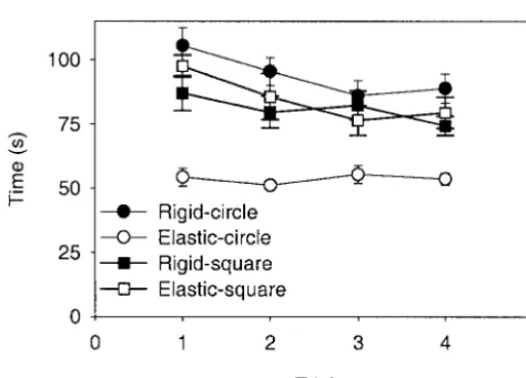
The data were analyzed using the same types of ANOVA as experiment 2. Effects of learning were inves-tigated separately for each combination of interface and obstacle. Repeated measures ANOVAs showed a learn-ing effect for the rigid-circular condition,F(3, 11)⫽
2.83,p⫽.05, but not for the elastic-circular,F(3, 11)⫽0.20,p⬎.05, rigid-square,F(3, 11)⫽1.47, p⬎.05, or elastic-circular condition,F(3, 11)⫽1.94, p⬎.05. (See figure 18.)
The remainder of the data that are reported here are the mean data for the two post-learning trials (trials 3 and 4). Two types of analysis were performed. First, the data for experiment 3 were analyzed using repeated measures ANOVAs. Then data for the human’s-eye (experiment 2) and tethered (experiment 3) view perspectives were com-pared using mixed-design ANOVAs that treated the view perspective as a between-participants factor.
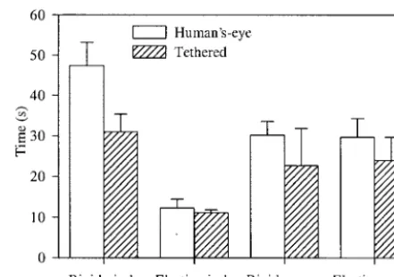
[image:15.630.315.551.91.261.2]Analysis of the mean time that participants took to complete the trials in experiment 3 showed no effect of interface,F(1, 11)⫽3.61,p⬎.05, or obstacle,F(1, 11)⫽1.96,p⬎.05, but there was a significant interac-tion,F(1, 11)⫽33.17,p⬍.01. Analysis of these data
for the two experiments showed that participants were significantly quicker with the tethered perspective than the human’s-eye perspective to perform the trials in the rigid-circular condition,F(1, 22)⫽4.81,p⬍.05, but there were not significant differences for the other com-binations of arm and obstacle. (See figure 14.)
The efficiency of participants’ movement was mea-sured by the angle between their body and the path. A repeated measures ANOVA of the data from experiment 3 showed a main effect of interface,F(1, 11)⫽15.84, p⬍.01, but not of obstacle,F(1, 11)⫽1.30,p⬎.05. However, there was a significant interaction,F(1, 11)⫽
10.02,p⬍.01. There were no significant differences between the tethered and human’s-eye view perspec-tives. (See figure 16.)
Analysis of the time that participants spent in collision during experiment 3 showed a main effect of interface, F(1, 11)⫽4.83,p⫽.05, but not of obstacle,F(1, 11)⫽0.17,p⬎.05. However, there was a significant interaction,F(1, 11)⫽37.53,p⬍.01. The percentage of the time spent colliding with the impassable side of the square obstacles was 44% with the rigid arm inter-face and 28% with the elastic arm. Analysis of these data for the two experiments showed that participants spent significantly less time in collision with the tethered per-spective than the human’s-eye perper-spective in the rigid-circular condition,F(1, 22)⫽5.13,p⬍.05, but there were not significant differences for the other combina-tions of arm and obstacle. (See figure 17.)
6.3 Discussion
The tethered view perspective proved straightfor-ward to use. The lag between a participant’s body move-ments and changes in their view position, caused by the technique used to reduce jitter, did not increase the levels of VE sickness from which participants suffered when com-pared with experiment 1 and 2. (In all three experiments, only minor symptoms occurred.) Use of a more sophisti-cated smoothing algorithm would reduce this lag and make a further improvement to the interface.
The pattern of results was similar to experiment 2 (for example, most time spent in collision in the rigid-circle condition and least time in the elastic-square condition),
but, as predicted, the differences between the four con-ditions were reduced. For all the types of data reported above, and all four interface/obstacle conditions, partic-ipants performed more quickly (or efficiently) with a tethered view perspective than with a human’s-eye view. However, the differences were small in magnitude and only significant for the rigid-circular condition (the car-rying time and collision time data).
7 General Discussion
In the real world, the movements that people make can be divided into those that require a high level of control and are the result of specific thoughts (such as “where do I want to carry an object?”), and those that take place at a low level and are largely automatic (such as stepping around obstacles or adjusting your hand position to compensate for the movements of an-other person). However, deficiencies in technology, par-ticularly in haptics, movement interfaces, and visual dis-play systems, mean that low-level aspects of motor control make substantial demands on our cognitive sys-tem in VEs. The result is that trivial real-world tasks such as carrying an object with another person are ex-tremely difficult to perform in a VE if a conventional interface is used. Fortunately, the virtual versions of such tasks can be made considerably easier if the inter-face software takes charge of some, or all, of the low-level components of interaction.
some-times caused participants to slide down the impassable side of an obstacle.
It is well known that most current desktop and HMD VE displays provide a severely impoverished FOV. A number of designers have counteracted this by imple-menting a tethered view perspective (Hindmarsh et al., 2000), which allows a user to see both themselves and their immediate surroundings in a VE. Until now, the only evidence in support of a tethered view has been anecdotal and subjective. As an example, some visitors to our laboratory have commented that the tethered view, in many respects, feels more natural than a hu-man’s-eye, even though it involves adopting an “out of body” viewpoint. Data from the present study now show that this type of view can also lead to improve-ments in objective measures of performance, and can usefully be applied to immersive VEs, not just those that use a desktop display. Also of importance are the fact that viewpoint jitter with the HMD was overcome using a simple orientation smoothing algorithm.
Finally, the present study used a simple carrying task, as was necessitated by the nature of the investigations that were being performed. Further studies are in progress involving the collaboration of two actual users and tasks that require the simultaneous carrying and manipulation of objects around obstacles. To support research in this area, the development of a taxonomy of motor operations and their levels of control is planned.
Acknowledgments
This work was supported by grant GR/L95496 from the En-gineering and Physical Sciences Research Council, and per-formed while Roy Ruddle was employed in the School of Psy-chology at Cardiff University.
References
Aretz, A. J. (1991). The design of electronic map displays.
Human Factors, 33,85–101.
Basdogan, C., Ho, C., Srinivasan, M. A., & Slater, M. (2000). An experimental study on the role of touch in shared virtual
environments.ACM Transactions on Computer-Human Interaction, 7,443– 460.
Broadbent, D. E. (1977). Levels, hierarchies, and the locus of control.Quarterly Journal of Experimental Psychology, 29,
181–201.
Cobb, S. V. G., Nichols, S., Ramsey, A., & Wilson, J. R. (1999). Virtual reality-induced symptoms and effects (VRISE).Presence: Teleoperators and Virtual Environments, 8,169 –186.
Craik, K. J. W. (1966).The nature of psychology.Cambridge: Cambridge University Press.
Ferrand, T., & Guiard, Y. (1995). Fitts’ law in cooperative two-person aiming. In B. G. Bardy, R. J. Bootsma, and Y. Guiard (Eds.), Studies in perception and action III
(pp. 65– 68). New Jersey: Erlbaum.
Hindmarsh, J., Fraser, M., Heath, C., Benford, S., & Green-halgh, C. (2000). Object-focused interaction in collabora-tive virtual environments.ACM Transactions on Computer-Human Interaction, 7,477–509.
Hooper, E. Y., & Coury, B. G. (1994). Graphical displays for orientation information.Human Factors, 36,62–78. Jacobson, J., & Lewis, M. (1997). An experimental
compari-son of three methods for collision handling in virtual envi-ronments.Proceedings of the Human Factors and Ergonomics Society 41st Annual Meeting1273–1277.
Kroemer, K. H. E. (1987). Engineering anthropometry. In G. Salvendy (Ed.),Handbook of human factors(pp. 154 –168). New York: Wiley.
Levine, M., Marchon, I., & Hanley, G. (1984). The place-ment and misplaceplace-ment of you-are-here maps.Environment and Behavior, 16,139 –157.
Mackinlay, J., Card, S. K., & Robertson, G. G. (1990). Rapid controlled movement through a virtual 3D workspace.
Computer Graphics, 24,171–176.
Ruddle, R. A., & Jones, D. M. (2001). Movement in clut-tered virtual environments.Presence: Teleoperators and Vir-tual Environments, 10,511–524.
Ruddle, R. A., Payne, S. J., & Jones, D. M. (1999). Navigat-ing large-scale virtual environments: What differences occur between helmet-mounted and desk-top displays?Presence: Teleoperators and Virtual Environments, 8,157–168. Wickens, C. D., & Prevett, T. T. (1995). Exploring the
di-mensions of egocentricity in aircraft navigation displays.
Journal of Experimental Psychology: Applied, 1,110 –135. Xiao, D., & Hubbold, R. (1998). Navigation guided by