WINDOWS ASSEMBLY
LANGUAGE & SYSTEMS
PROGRAMMING
16- and 32-bit low-level programming
for the PC and Windows
2nd edition
bY
Barry Kauler
Lecturer, Edith Cowan University M.Sc.(EE), C.Eng.
All rights reserved. No part of this publication may be reproduced, stored in a retrieval system, or transmitted in any form or by any means, electronic, mechanical, photocopying, recording, or otherwise, without prior written permission of the Publisher. In this book, many of the designations used by manufacturers and sellers to distinguish their products may be claimed as trademarks. Due acknowledgement is hereby made of all legal protection. WindowsTMis a trademark of Microsoft Corporation.
Disclaimer. Whilst due care has been taken in the preparation of this book, no responsibility is accepted for any inaccuracy, loss or damage to data, or consequential loss or damage. The content of the Companion Disk is not guaranteed to be exactly as described.
This edition published by R&D Books / Miller Freeman ISBN: 087930474X
DISTRIBUTION: USA
Publishers Group West P.O. Box 8843 Emeryville, CA 94662 Tel: (800) 788-3123 Fax: (510) 658-1834
UK and Europe
McGraw-Hill Publishing Co. Shopper&angers Road Maidenhead
Berkshire SL6 2QL United Kingdom
Tel: 0800 810800 or 01628 502500 Fax: 01628 770224
e-mail: [email protected] Latin America
ID International
126 Old Ridgefield Road Wilton, CT 06897 USA Tel: (203) 834-2272 Fax: (203) 762-9725
Canada
Publishers Group West Canada 543 Richmond Street West Suite 223
Toronto, Ontario M5V lY6 Canada
Tel: (416) 504-3900 Fax: (4 16) 504-3902 Asia
Longman Singapore 25 First Lok Yang Road Singapore 2262
Tel: 65 268 2666 Fax: 65 268 7023
Editorial & Marketing Oftice R&D Books
1601 West 23rd Street, Suite 200 Lawrence, KS 66046
Contents
Ch.
Preface
Page xi
1 CPU Architecture 1
Preamble ...1
Power-up the PC ... 2
The System Files... 3
Number Systems ... 6
Registers and Memory . . . 9
MemoryMapofthePC . . . 12
The CPU & Support Chips ... 12
Conventional and Extended Memory ... 14
Segments ... 14
Real Mode ... 17
DOS Real Mode Programming ... 18
DOS Protected Mode Programming ... 18
Coding Restraints ... 20
Inside the 286/386l486/etc. ... 2 1 CPU Registers ... 22
Instructions ... 23
Real and Protected Modes ... 25
Memory Management ... 25
Segmentation Only... 25
Shadow Registers . . . 26
Descriptors . . . 28
386 Paging... 28
Virtual-86 . . . 29
Contention Issues ... 3 1 Privileges.. . . 31
I/O Privilege ... 3 1 Task Switching ... 32
Interrupts ... 3 3 Real Mode Interrupts ... 33
Protected Mode Interrupts ... 34
Postamble ... 36 ..I
Ch. Page
2 Basic Assembly Language 37
Preamble ... 3 7
Stack Instructions ... 38
Transfer of Control... 39
Conditional Jump ... 43
Addressing Modes ... 44
Segment Registers ... 46
String Instructions ... 47
Arithmetic Instructions ... 50
Logical Instructions ... 54
Code and Data Labels ... 56
Code Labels ... 56
Data Labels ... 58
Accessing Data ... 5 8 Pointers . . . 59
LES, LDS, and LEA Instructions ... 60
Local Data ... 62
Type Override ... 63
Structures . . . 65
Label Equates . . . 66
Postamble ...67
3 Opening Windows 69 Preamble ...69
DOS versus Windows Programming ... 70
Internal Differences ... 7 1 Building a Windows Application ... 72
Library Functions ... 72
The Mechanics of Assembling and Linking ... 73
The Link Step ... 74
Two Steps for Resources ... 74
Windows Programming Mechanics ... 75
Objects ... 75
Handles ... 76
Instances ... 76
Messages ... 77
C Syntax ... 78
Message Loop ... 78
Callback Functions... 79
V
Ch. Page
4 The Bare Bones 85
Preamble ... 85
Getting Started ... 86
Tools Required . . . 86
Source Files . . . 89
Resource and Definition Files . . . 89
Message Format . . . 90
Make File ... 91
Development Cycle . . . 92
Application Structure . . . 94
Preliminary Code . . . 94
Startup Code . . . 96
WINMAIN{) . . . 98
Callback Function . . . 102
5 High-Level Assembly 109 Preamble ... 109
Include Files ... 109
Microsoft versus Borland ... 110
Skeleton Analysis ... 111
.MODEL Directive... 119
Private and Global Data ... 120
MASM versus TASM Scope ... 121
TASM’s @@ ... 121
Life of Automatic Data... 122
Assembling and Linking ... 123
MASM6 versus TASM ... 125
WINDOWS Qualifier ... 126
Prototypes ... 127
Callback Design . . . 129
Other Incompatibilities ... 130
MASM Assembling and Linking ... 13 l MASM6 Program Listing ... 132
6 Program Design 137 Preamble ...137
Object Addressing ... 138
Calling a Function ... 138
Early Binding ... 14 1 Late Binding ... 142
Ch. Page
Assembly Language Binding ... 145
Use of THIS ... 145
Interfacing with C++ ... 147
Compiling to ASM O/P ... 147
In-Line Assembly ... 148
In-Line DOS and Don’ts ... 149
The ASM Stub ... 150
Compile and Assemble Steps ... 15 1 The Amazing 9-Line Program ... 153
A Skeleton Program ... 154
Overrides . . . 156
Kickstart . . . 157
Message Handling . . . 157
The WINDOW Object ... 158
WINMAIN ) . . . 162
Callback ... 165
MA=( ) . . . 168
Inheritance . . . 171
Getting it Together ... 175
Postamble ... 178
7 PC Hardware 179 Preamble ... 179
CPU bus ... 179
Control Bus ... 180
Address Decoder... 182
I/OPorts . . . 183
I/O Instructions ... 184
Keyboard Interface... 184
AT-Class Keyboard Port Enhancements ... 186
PC Expansion Buses ... 187
Industry Standard Architecture (ISA) ... 188
Peripheral Connect Interface (PCI) ... 19 1 Postamble ... 194
8 BIOS, DOS, & Windows Low-Level Services 195 Preamble ... 195
BIOS and DOS Services ... 197
Standard DOS Interrupts ... 200
DOS Protected Mode Interface (DPMI) ... 203
vii
Ch.
9
10
11
Page
Windows Functions ... 207
Thunking ... 219
Generic Thunking . . . 219
More Win95 “Improvements” ... 222
Device I/O Control . . . 222
Dynamically Loadable Drivers ... 223
Threads ... 223
Memory Mapped Files ... 224
Postamble ... 224
Direct Hardware Access 225 Preamble ... 225
Initialisation ... 226
Addressing Segments ... 227
Direct Video . . . 229
Restore Video ... 23 1 Change Video Mode ... 232
A Direct-Video Text-Mode Routine ... 232
Call REPAINTSCREEN . . . 234
Ordinal Coordinates . . . 235
To and From Text Mode ... 236
Video Output Issues ... 237
MessageInput . . . 238
Experimenting ... 239
A Direct-Video Window Program ... 239
I/O Ports ... 244
Real-Time Events 249 Preamble ... 249
TSRs ...250
Hooking a Vector . . . 251
Service Routine (ISR) ... 253
Testing . . . 255
Hardware Interrupts ... 256
XT Hardware Interrupts . . . 256
AT Hardware Interrupts ... 257
Windows’ Standard Mode Hardware Interrupts ... 258
Interrupt Handler Code... 260
Enhanced Mode Hardware Interrupts ... 263
Direct Memory Access ... 264
Figure 1.12: Memory management. 386 CPU
pz?ii
1 G D T - r e g i s t e r t\
This is the internal format of the segment registers (selectors) CS, DS, etc.
* = 0 if pointing to the GDT, * = 1 if pointing to
an LDT.
r PI =
requestedprivilege level.
Each entry in an LDT or the GDT is called a
“descriptor” & has they address of a segment.
1
Actua 1 memory
LDT. task 1
LDT, task 2 . . . task 3, etc.
program segment data, code, or stack
A s s o c i a t i o n The next step in this saga is that the CPU can use the selector in b e t w e e n the CS register to index into the current LDT and get the actual d e s c r i p t o r address, or more correctly the descriptor, of the code segment. ands/radow The IP register (or EIP) will have the offset into that segment from r e g i s t e r which the CPU wiII fetch the instruction.
28 Windows Assembly Language & Systems Programming
The CPU will only have to look in the shadow register to find out the starting address of the segment (plus some other information) and can then go ahead and put together the full 32-bit address for fetching the instruction.
The CPU will add the base address to the offset IP and get a 32-bit address that can be put onto the address bus.
Descriptors
I have introduced the descriptor as being an entry in the GDT or LDT. There are various types of descriptors, but the most common is the normal addressing type that we have been discussing so far.
Each descriptor is 8 bytes in size, and Figure 1.13 shows what a normal descriptor looks like.
Figure 1.13: Descriptor format.
64 55 47 39 15 0
base+ # access base limit
I Size of Normally set “Base” is the address segment. to zero on the of the segment.
286.
“Base+” extends the base segment addressing beyond 24 bits. “#“extends the limit beyond 64K.
AC&?SS field The access byte in Figure 1.13 has various flags and codes. It has a two-bit DPL field (Descriptor Privilege Level) that determines the privilege level of the segment. It has P (Present) and A (Accessed) bits that are used for moving the segments in and out of memory. There are R (Read) and W (Write) bits that set constraints on reading and writing the segment. There is also the C (Conforming) bit and ED. The latter is set if the segment is a stack.
I go into the description of the descriptor in far greater detail in Chapter 12.
386 Paging
What’s wrong with segments?
Page tables and control registers
Linear address
I’ll look first at the one built on top of the desriptor tables. From our program point of view it Iooks just like the segmentation mechanism with the GDT and LDTs. The only difference is that the CPU secretly stores the segments in actual memory not in one contiguous chunk, but all over the place as 4Kpage.s.
Why go to this trouble? The operating system has trouble bringing segments in and out of memory because they are all different sizes - if a new segment is to be brought in, space must be found for it, but space released by a segment that has vacated its spot may not be the right size. This is a real problem for the operating system, and it ends up with lots of little unused gaps everywhere. Inefficiency.
By transparently parcelling the segment up into lots of little pages all the same size and storing them wherever there is a space, the mismatch of segment sizes is no longer a problem. We know that a space vacated by a departing page will be exactly the right size to take a new page. No problem.
Well, there is one. To achieve this, more translation tables are required, called page tables. The CR registers are used to address these, and the page tables are kept in memory just like the descriptor tables.
The CPU has various extra registers for maintaining the paging mechanisms, most importantly, CR3, which contains the base address of the Page Table Directory.
Just for the record . . .
The address computed from the descriptor table, now renamed the linear address (as it is no longer the final physical address), is divided into fields, with bits 22 to 31 being an index into a page-table directory that gives the address of a particular page table. Bits 12 to 21 are the index into this second table, which contains the final address. Bits 0 to 11 are unchanged and become part of the final address.
You will come across the words linear address later in the book. Note that sometimes the words virtual address are used in various books to mean the same thing, though there is a distinction. The linear address is that 32-bit address that would be the physical address if page tables didn’t get in the way.
Virtual-86
30 Windows Assembly Language & Systems Programming
Paragraph addresses are back!
Vhtual
This mode is fascinating. It also does away with selectors and brings physical segment (paragraph) addresses back into the segment registers! Thus we come full circle, but with a vital difference.
Although the 16-bit segment address is back, and once more programs designed to directly manipulate segment registers can do so. The CPU does compute a 20-bit address consisting of paragraph address plus offset, but this is not put on the external address bus. Instead, it is processed via page tables, that is, translated to some other 32-bit address then put onto the address bus.
Once again, this paging is transparent to the programmer, but it does mean that the program, data, etc. are not where you think them to be judging from the segment registers.
[image:39.513.55.401.291.514.2]Virtual-86 mode is useful not just for emulating the old XT computer, but is the very foundation of Windows Enhanced mode. True, each virtual machine will have an addressing limit of lM, but Windows can create many of these (Figure 1.14).
Figure 1.14: Virtual Real mode.
Appar-ent 1M address
i space.
1 Virtual XT PC
I
Virtual XT PC386 PC
Jbe upper8 Instead of putting the 20-bit linear address onto the address bus, as
bits of the for Real mode, virtual-86 mode uses the upper 8 bits of this linear address as a lookup in the current page table - note that the table address are entry contains the base address of the page, which is combined remapped with the lower 12 bits of the linear address to form the actual32-bit address. It is this final 32-bit address that the CPU puts out
Four
privilege
levels
IOPL f i e l d
IN,
OUT, CL!,
and ST/
So what happens if your program writes directly to video RAM at segment B800? This is up to the operating system, which most likely will create virtua1 screens for each task, setting them up anywhere it wants to in RAM.
Contention Issues
There are various things to think about under this heading, but I have at this stage just addressed the issues of privileges, I/O, and task switching.
The topics are brought up at various points through the book, so look in the Index for other page references.
Privileges
The dpl field in the descriptor defines the privilege level of that segment. Also you will see back on page 27, Figure 1.12, that the selector has a requested privilege level (rpl).
Because it is a 2-bit code, there are four possible levels, zero being the most privileged. The kernel of the operating system will operate up here (zero), while your lowly program will reside at a lower privilege level.’
Your program’s level is basically reflected in what the rpl is set to, and this must be numerically equal to or less than the segment’s dpl to allow access to that segment - otherwise the CPU exits to an error routine and the dreaded UAE (Unrecoverable Application Error) dialog box appears, and that’s the end of your program!
I/O Privilege
Privilege levels do have some impact on I/O. If you look at the FLAGS register (see page 244), you’ll find 2 bits that hold the Input/Output Privilege Level (IOPL). Your application must have a privilege level numerically equal to or less than this to be able to perform I/O. With Windows, the IOPL field is set to zero, most privileged.
However, it is possible for the operating system to give permission for certain I/O to occur, even though the application doesn’t have the right privilege. I/O access involves use of the IN and OUT instructions and control of the interrupt flag by CL1 and ST1 ’ Windows 3.0 runs WinApps at level 1, DOSApps at level 3, and DLLs at level 1. Windows 3. I
32 Windows Assembly Language & Systems Programming
PUSHF, POP/
Changing Lors
lask State Segment
instructions. The interrupt flag is in the FLAGS register and when cleared, prevents hardware interrupts from occurring.
If the application has sufficient privilege to perform direct I/O, it can also set and clear the interrupt flag. Although a Windows program does not have the privilege of direct I/O, Windows does allow it, to an extent. If I/O is attempted, the CPU goes to a Windows error (exception) routine, which does have the privilege to do what it wants - the routine allows CL1 and ST1 (clear or set interrupt flag instructions) but does not let PUSHF or POPF instructions affect the interrupt flag. This is something to be aware of and a possible source of incompatibility with old DOS code. It also means that an IRET from an interrupt routine may not set the flag as it was prior to the interrupt.
For more information on I/O, refer to page 244.
Task Switching
Considering the complications of multitasking, I sometimes wonder if it is all worth it. Perhaps a more effective solution would have been multiple CPU-boards, each single-tasking. Anyway, we are stuck with the current situation.
Changing from one task (program) to another is a matter of changing to a new LDT,’ which involves the CPU looking into the GDT and getting the new LDT’s address.
However, the “state” of the task about to be suspended must be saved, and the “state” of the incoming task must be restored. This state consists of the CPU and coprocessor registers plus various memory pointers and values, and an incredible time overhead is involved to save and restore this lot.
The CPU has to maintain a special segment for each task, called the Task State Segment (TSS), into which all of this goes. Then, of course, the CPU must keep track of where these TSSs are, so it maintains descriptors for the TSSs in the GDT. Thus the GDT contains more than just descriptors for the LDTs.
Interrupts
Real mode interrupts
Like everything else, Protected mode interrupts are a whole new ball game. First, let’s review the mechanism in Real mode.
The standard method of doing I/O and file and memory management, plus a heap of other operations, was by the BIOS and DOS interrupt services. These are accessed from an application program by means of the INT instruction, with this syntax:
INT n :software interruDt
MT-2 lb, fbe
main DOS service
Windows functions
Interrupt Vector Table (/VT)
where “n” is an integer (whole number) from zero to FF (hex). The usual procedure is that certain registers have to be loaded prior to the INT, depending upon the particular service, and many of the services have subfunctions, usually selected by a value in the AH register.
The most important of these is INT-2lh (h = hexadecimal), which is the main DOS service, with dozens of subfunctions.
A comprehensive list is to be found in my previous book. In this one you’ll find extra INT services especially relevant to Windows. It is not that we do away with INT services entirely with Windows, it’s just that many of the BIOS and DOS services are designed for DOS and the Real mode and are no longer appropriate.
We access the Windows services by CALL instructions, not INTs, and from the CPUs point of view there is a difference. Windows’ services, or functions, do all that many programmers would want, though we dig a little deeper in this book and also show how useful the INT services can be.
Real Mode Interrupts
Interrupts, whether from an external source (hardware) or generated internally by the program (software), cause the same reaction in the CPU:
1. The CPU pushes the current Instruction Pointer (IP), Code Segment (CS), and FLAGS register onto the stack.
34 Windows Assembly Language & Systems Programming
3. The CPU then loads the FAR address into its CS:IP registers and commences execution of the service routine.
4. Interrupt routines always terminate with an IRET instruction, which has the effect of popping the three values saved on the stack back off, into CS, IP, and FLAGS. Thus the CPU carries on as before, as though nothing had happened.
IRET Note that when a CALL instruction executes, it works in a similar
instruction way, but a FAR CALL only saves CS and IP on the stack, not the FLAGS. Also, if it is a NEAR CALL, only IP is saved on the stack. In addition, the routine called must terminate with RET, not IRET, as the latter pops three values off the stack (expecting FLAGS to be on there as well).
CALL to an Incidentally, a useful point arises from what I have written above.
ISR You can use the CALL instruction to call the BIOS and DOS services, despite the fact that they terminate with an RET:
PUSHF
CALL rou tinename ;push flags on stack.
Structure of the /VT
Interrupt Descriptor
Table (ILIT)
That is, you push the FLAGS on beforehand, using a special instruction, PUSHF (there is also a POPF). You do need to know the address of the routine that you are calling, however, since it doesn’t make use of the IVT, as INT does.
Protected Mode Interrupts
Just as segment registers no longer represent real addresses, so too the interrupt mechanism no longer uses the Interrupt Vector Table (IVT). Interestingly, when Windows is running, the IVT is still there, but our applications don’t use it. It is still used by Windows, but that’s another story.
So, just where is this IVT? Have a look back at page 11. The IVT sits in RAM right down at OOOO:OOOO, occupying the first 1024 bytes. It is set up by the BIOS startup routine and filled in by DOS also.
Using INT within WinApps
Redirection oflDTto/VT (Protected mode to Real mode)
Virtua/
MS
There is a fascinating outcome of this. From within a Windows application, you can have an INT instruction - let’s say that you want to call the BIOS INT-1Oh service, which controls the video adaptor. INT-1Oh is not a service that Microsoft would want you to call from your application, since all control of the video should be done by the Windows functions - but you can do it.
A warning here: some services will crash if called while in Protected mode, and others will behave strangely.
Microsoft has in some cases provided alternative BIOS and DOS services, written especially to run in Protected mode, and when your program executes, say, INT-2lh/AH = 35h, the CPU will look up that entry in the IDT (not the IVT) and get the address. Thus it is very easy for Microsoft to substitute its own services into the IDT.
In many cases (probably most) Microsoft services have not been substituted, and execution goes to the original BIOS or DOS service. Although the Real mode services may in some cases manipulate addresses in the form segment:offset, which will cause the code to crash if the CPU is running in Protected mode, Windows gets around the problem by switching the CPU into Real mode, or into virtual-86 mode, then calling the service.
For such cases, the entry in the IDT points to a special handler, which, apart from changing the CPU to Real mode, must also convert any pointers from selector to segment value. Then the handler will have to look in the IVT to get the address of the Real mode service.
Thus, even the services in the BIOS-ROM will work. At least they will return without crashing the system (in most cases), though whether they do what you want is another matter.
Note however, that there is a difference in accessing interrupts from a 32-bit compared with a 16-bit Windows application. This is a complicated issue and is developed in Chapter 16.
Another fascinating thought occurs about virtual-86 mode, which uses the IVT, but in plural. Although there is an IVT at actual physical address OOOO:OOOO, each virtual-86 task will have its own copy of the IVT, which appears to be at OOOO:OOOO but is paged anywhere. You need to be aware of this proliferation of IVTs if you want to hook a vector.
36 Windows Assembly Language & Systems Programming
Postamble
2
Basic Assembly
Language
Preamble
Content of this chapter
This chapter contains an introduction to assembly language for the x86 family of processors. The focus is on 16-bit programming. Later chapters will expand this to 32-bit programming.
Real mode 16-bit programming can be considered an essential step up the ladder of understanding, climbing through 16-bit Protected mode, toward 32-bit Protected mode programming.
Chapter 4 puts this knowledge to use in a first 16-bit Windows application.
Discussion relates to the Microsoft and Borland assemblers, though of course there are other compatibles.
38 Windows Assembly Language & Systems Programming
fnitiafisation of the stack
P u r p o s e o f the stack
*.. t e m p o r a r y
s t o r a g e
,,a C A L L / R E T
*.* interrupt m e c h a n i s m
Stack Instructions
The computer maintains a stack somewhere in memory. DOS will set the Stack Segment register SS when your program is loaded, and the Stack Pointer SP will be initialised to FFFEh, or some value that means the stack is empty. The stack is used by the computer and by your program. For example, whenever an interrupt occurs the CPU pushes the IP, CS, and FLAGS onto the stack, so that when the interrupt routine is finished (terminated by an IRET instruction) the CPU will pop these values back into the respective registers and continue from where it left off.
Thus the stack is used to hold register values to enable the CPU to return from an interrupt and also from a procedure CALL.
However you can make use of the stack in your program, by means of the PUSH instruction, which pushes a 16-bit value onto the stack, and POP, which pops the top value off the stack into a register or memory location. Also PUSHF and POPF can be used to push the FLAGS onto the stack and pop them off.
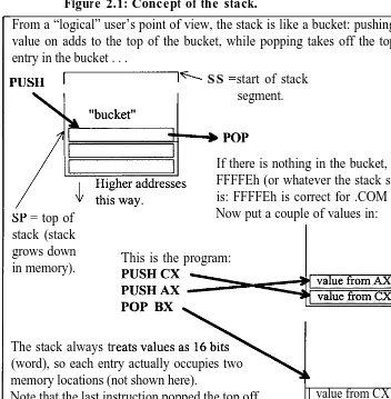
Whoa! This is a lot to think about! I’ve just stated above that there is a memory area called a stack, that it is used by the CPU to store register values for interrupt and CALL-instruction execution, and it is used by the PUSH and POP instructions. You may find it extremely helpful at this point to visualise what is happening. Look at Figure 2.1 and examine the effect of the PUSH and POP instructions.
In Figure 2.1 you see two instructions, PUSH and POP, that you can use in your program. You can push values onto the stack, and take them off again - why? - one reason is that it serves as a convenient temporary storage.
I also mentioned that the stack is used by the CALL instruction -this is one of the “transfer of control” instructions and is described in the next section.
I mentioned that interrupts also use the stack - again, explanation is deferred.
Figure 2.1: Concept of the stack.
From a “logical” user’s point of view, the stack is like a bucket: pushing a value on adds to the top of the bucket, while popping takes off the top entry in the bucket . . .
PUSH _% SS = start of stack
segment.
If there is nothing in the bucket, SP= FFFFEh (or whatever the stack size is: FFFFEh is correct for .COM tiles). SP = top of
stack (stack grows down in memory).
Now put a couple of values in:
This is the program:
The stack always tr
(word), so each entry actually occupies two memory locations (not shown here).
Note that the last instruction popped the top off the stack, into BX.
value from CX I
The stack is a temporary storage area, whose actual address we don’t need to know. It does have a limitation: when SP=O the stack is full.
Transfer of Control
40 Windows Assembly Language & Systems Programming
The CPU executes the instructions sequentially - that is, one after the other in order of increasing addresses - but can also jump out of sequence.
LOOP, JMP, The topic of this section is those instructions that cause execution
[image:49.507.49.404.154.440.2]CALL. /NT. to go to some other place in the program. The main ones are: JX . . LOaP, Jh4P, CALL, I&T, and Jx. in this section we will examine CALL, JMP, and Jx. LOOP and INT are examined a little bit later:
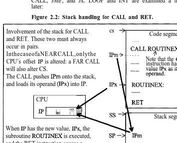
Figure 2.2: Stack handling for CALL and RET. Involvement of the stack for CALL
and RET. These two must always occur in pairs.
cs :
Code segment . . . . .
InthecaseofaNEARCALL,onlythe IPm 3 . . . .CALL RYTINEX CPU’s offset IP is altered: a FAR CALL Note that the instruction has theCALL
will also alter CS. value IPx as its
The CALL pushes IPm onto the stack, and loads its operand (IPx) into IP.
CPU
IPI, .,.;,; ‘_::
Stack segment When IP has the new value, IPx, the
subroutine ROUTIAEX is executed, and the RET instruction causes a return to the caller, by popping IPm off the stack, back into IP.
SP+ IPm . . . . . . . .
Figure 2.2 illustrates how the CALL and its companion RET use the stack. The basic idea is that the value in the Instruction Pointer, IP, is always the next instruction to be executed, so when “CALL ROUTINEX” is executing, IP will have IPm in it. Since the value in IP has to be changed to the subroutine, IPx, the return value has to be saved somewhere: hence the stack is used to save IPm. The RET instruction must always be placed at the end of a procedure, as it pops the top off the stack, back into IP.
FAR and NEAR
Code labels
Code /abeIs with MASM, TASM, DEBUG
What is DEBUG?
compiler translates the high-level source code to machine instructions.
This topic does need some careful thought. Any CALL, RET, or JMP instruction can be a FAR or NEAR jump. What this means is that if the jump is NEAR, the jump is only within the current code segment; that is, only the IP is altered, as per Figure 2.2.
A FAR jump or call, however, can be to anywhere in the entire 1M address range, as both CS and IP are altered. In Figure 2.2, the procedure ROUTINEX is shown as being in the same code segment as the CALL instruction, but it could be somewhere entirely different. Obviously, if ROUTINEX is in a different code segment, then both CS and IP in the CPU would have to be changed to the new values.
Note that it also logically follows that the original values of CS:IP, immediately after the CALL, would both have to be saved on the stack, and RET would have to restore both of them at the end of the procedure.
Note that with what is called 32-bit programming, the distinction between NEAR and FAR just about disappears.
One thing that you will notice from Figure 2.2, is that I used a code label, ROUTINEX, to name the start of the procedure. This is basically what you expect to be able to do in any high-level language, and you can also do this in assembly language. A code label marks, or identities, that point in the code, hence a CALL was able to be made to that place.
With a professional assembler, such as the Borland TASM, or Microsoft MASM, these labels are a normal part of writing a program, but DEBUG is a different story.
DEBUG CANNOT HAVE LABELS!
With DEBUG any instruction that transfers control to another address must contain the actual offset.
What is DEBUG? It is a program that comes with DOS, and from the DOS prompt you will only have to type the name of the program to execute it. DEBUG.EXE is a way of becoming familiar with the instruction set - it allows you to try out the instructions and put together simple programs.
These examples show that DEBUG must have an actual address, not labels:
MOV CX,9
PLACEl: I*this is at 113 (say) MOV AX,0
LOOP 113
-arbitrary instr I
42 Windows Assembly Language & Systems Programming
ibbP PLACE1 ;using a l a b e l .
JMP instructiofl
SHORT, NEAR, and FAR
However, by writing the code in “proper” assembly language, we do not need to know actual addresses. The second example here shows how a proper assembler can have a symbolic address marker, in this case PLACE1 .
In Figure 2.2, we looked at a CALL instruction, but there is also a JMP (jump) instruction that transfers execution to the address specified in its operand in the same manner as the CALL instruction, but with a major difference: no return address is saved on the stack. This is because JMP is used when you do not want execution to come back.
It was also explained above that the CALL can be NEAR or FAR, but the JMP can be SHORT, NEAR, or FAR.
The example code below shows a JMP to a label. Usually, an assembler defaults to a NEAR jump, as the destination is usually in the same segment.
jmp PLACE1
PLiCEl: ;code l a b e l .
mov ax,0 ;arbitrary i n s t r u c t i o n .
[image:51.508.101.362.401.482.2]At this point, it is instructive to consider how the assembler will assemble this .lMP instruction into memory. Obviously, it has to be converted to “machine language”, or binary bits. That is what any compiler or assembler does.
Figure 2.3: Generation of machine code, NEAR jump. Increasing
addresses downward
In Figure 2.3 you can see the basic scenario. The first one (or sometimes two) memory location(s) contain the instruction-code, or operation-code, often referred to as the op-code, that identifies this as a JMP instruction (or whatever), while the following zero or more bytes are the operand.
FAR JMP
SHORT JMP
Range of a SHORTjump
byte addressing, meaning that each address addresses a one-byte (8 bit) memory location.
Therefore, the operand requires two memory locations, as shown in Figure 2.3 as operand-low and operand-high. The Intel x86 convention is that the low-half of the value is stored at the lower address.
It is also useful to note that if the IMP is a FAR jump, that is, to another code segment, the operand of the instruction will have to contain the destination CS:IP, which is two 16-bit values. Hence it would be 32 bits.
The FAR jump would assemble as the one-byte (or two) op-code, followed by a one-word IP then one-word CS value. Note that the FAR jump can also jump within the current code segment but is slightly inefficient because it is a longer instruction, taking a little longer to execute and using more memory.
The IMP instruction has one interesting difference from the CALL: it is able to perform a SHORT jump. This is shown in Figure 2.4:
Figure 2.4: SHORT jump machine code.
Iancrcesiey Operation-code
. Fl downward Operand
\1
This reduces the instruction down to the one-byte (g-bit) op-code followed by a one-byte 2%complement displacement. This displacement allows jumps to be only +127 to -128 about the current IP position.
In some circumstances, the assembler will automatically make the jump SHORT, but it can also be forced to, by means of the
SHORT directive.
Conditional Jump
44 Windows Assembly Language h Systems Programming
and the conditional jump instructions can be used to test the flags and jump accordingly.
Below is a summary of the conditional jump instructions: JZ ,.jump if previous result was 0
JNZ ;jump if previous result not 0
JGrea ter ;this means "if the SIGNED difference is positive"
JAbove ;this means "if the UNSIGNED difference is positive" JLess ;this means "if the SIGNED difference is negative" JBelow ;this means "if the UNSIGNED difference is negative" JCarry ;assembles the same as JB.
When using these instructions, you do not enter the part in italics.
Signed and Note that when comparing two values, we need to distinguish
unsigned between whether the values are unsigned or 2’s complement.
compare Here are simple examples:
ADD AX,VALl
JZ ZERORESULT ;jumps if previous result=O(zero-flag ; set) &1;, AX,56 *compare instr.
JA ABOVE56 ljumps if AX>56
ivariations . . .
JNC place1 *jump if Carry flag=0 JE place1 isame as JZ ("Equal")
JAE place1 ;unsigned jump, if above or equal. JBE place1 I*unsigned jump, if below or equal.
The ADD instruction, given as an example above, is explained a little further on. Ditto for the CMP instruction.
Note that "ZERORESULT", "ABOVES~", and "placel" are code labels, chosen to have meaningful names.
Addressing Modes
Obviously, the instructions of your program will be accessing registers and memory, and the mechanisms by which this is done are called the addressing modes.
The best way to show this is by example: VALl DW 0
MOV Ax,VALl I*direct addressing mode.
MOc/ The humble MOVe instruction is the equivalent of the LoaD-Act insfrucfio~ and STore-Ace instructions of the 6800 CPU, for those who have had exposure to that beastie. It simply moves a value from one place to another, in this case copying the value of BX to AX.
Register &
Because only registers are involved in the first instruction of theimmediate
above example, this is called register addressing.addressing
The same MOV instruction appears again on the second line, but note that a value is specified this time. This value is NOT an address; it is an immediate value that is loaded into AX. This is called immediate mode addressingDirect
Now this is different. The square brackets of the third instructionaddressing
signify “the contents of’ and it is the contents of address 567 thatis loaded into AX (there is a qualification to the above comment, as the example loads the AX register, which is 16 bits, from a memory location, which is 8 bits).
Note too that with an assembler (not primitive DEBUG though) any address can be replaced by a label, so if you had defined address 567 as being represented by label VALl (for example), then this would do the same thing:
Both of these are called direct addressing.
[Jsyntax
Do note one point about syntax. The last instruction could have square brackets around VAL 1, and it would be interpreted exactly the same by the assembler (TASM or MASM).Indirectand
Indirect addressing is somewhat more abstract. It means that theindexed
contents of the operand are used as the address. So, the content ofaddressing
BX is the address from which the value is fetched into AX:mov ax, [bxl -indexed addressing mode. mov ax, [bx+51
j$ mov ax, [bx+si+51
That just about covers it, except that indirect addressing does have some options, as shown in the last two instructions above.
The first one adds the contents of BX to 5, and the result is the address, while the second example adds the contents of BX, SI, and 5 to form the address. This modified form of indirect addressing is called indirect plus displacement if a constant is specified, or indexed indirect if two registers are specifed.
Restrictions
Note that we often just label these various indirect modes under onindexed
the title of indexed addressing.46 Windows Assembly Language & Systems Programming
Note also, that there are restrictions on the combinations of registers allowed within the brackets: you can have SI or DI, but not both, and you can have BX or BP, but not both. No other registers are allowed.
Segment Registers
Another thought: how do you access data in DS, the data segment? This is the place to keep data, so obviously your program must be able to get to it. Simple: most instructions automatically reference the DS.
For example, the listing below shows how VALl is defined and referenced:
.DATA
VALl DB 0 I-in data segment. .&E
mov ax,VALl *in code segment.I
Later, you will see more details on how to use the assembler, so don’t worry about that side of things. Suffice to say that you can define a label in the data segment and reference it from the code segment.
When the program is assembled, the address of VALI will be put into the operand of the MOV instruction: note however that this is an offset relative to the DS.
Most importantly, when your program is executed, it must have DS set to the beginning of the data area, as the MOV instruction will automatically use DS to compute the physical address.
Sometimes, especially with pop-up and interrupt routines, the program may be entered with DS not set correctly, so you have to take care of that at the beginning of the program.
Segment override
Although the MOV instruction in the above example automatically referenced the DS register, it is possible to override this. For example you could have data in the code segment, so your program would have this:
.DATA
.&DE
jmp place1
VALl DB 0 ;data d e f i n e d i n c o d e s e g m e n t . placel:
Some notes on this: . COM format l
ES register
C o n c e p t o f the string iflstructions
W/B pos ffix .
In the case of .COM programs CS = DS = SS, so the question of override doesn’t arise normally. With a .EXE program, data could be kept in the code segment, as long as execution jumps around it: but note also that OS/2 and other operating systems that operate the 286 and 386 CPUs in Protected mode, may be very unhappy with data kept in the code segment/s. Sometimes data is kept in a segment pointed to by ES (or FS and GS in the 386), so ES override might be useful in this situation. The BP register, although a general-purpose register, is treated by the assembler as an offset into the stack segment, SS, by default. Thus, if you want to use BP to access data in segments pointed to by DS or ES, an override is required.
String Instructions
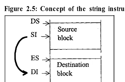
This group of instructions are designed for moving blocks of data from one place in memory to another, and some of them are for searching through and comparing blocks of data. The word “string” does not necessarily imply text, but any block of data. Mostly you will use the string instructions responsible for moving data around, such as MOVS, LODS, and STOS. Basically, you have the source block in one part of memory and the destination somewhere else, and you have to set certain registers to point to these source and destination areas before using the string instruction.
The string instructions have an “implied” addressing mode, in that they use certain predetined registers, as shown in Figure 2.5. Figure 2.5 is a picture of memory. DS:SI is where the data is, and ES:DI is where it’s sent.
MOVSB, for example, would read a single byte from DS:SI, copy it to ES:DI, and automatically increment both SI and DI, so that the next time the instruction is executed the next byte will be copied.
48 Windows Assembly Language & Systems Programming
Figure 2.5: Concept of the string instructions.
Auto-increment
Directiofl flag, DF
REP
prefix
String operations make use of SI and DI to point to the source and destination strings respectively, and they are automatically updated each time the string instruction is executed.
There is a direction flag, DF, that is cleared by instruction CLD, and set by instruction STD. If DF is clear, the string instruction will automatically increment SI and/or DI to point to the next byte or word, and if DF is set they will be decremented. It is normal to operate on a string starting from the lowest address in memory, so use CLD before a string operation (this is the default for the 80x86 family anyway).
DF is one bit of the FLAGS register, shown on page 244. CLD and STD are described in the Appendices.
REP is a prefix, placed on the same line and before a string instruction. It means “check if CX = 0, if not perform the string instruction, decrement CX, then start again”. Example:
mov cx,str_length
rep movsb ;repeat with cx = count.
A variation on this is REPNE, which is basically the same but will also terminate if the zero-flag is set.
REP variations are summarised in the Appendices.
LOOP Note that the LOOP instruction can do much the same as REP.
instruction Again, CX is decremented before CX is compared with zero, so MOVSB will be executed exactly the number of times originally loaded into CX. The loop will terminate with CX = 0. There are some variations on the basic LOOP instruction: have a look in Appendix A.
again: I*code loop does same as above. movsb
l o o p a g a i n I*loop i s a n a c t u a l i n s t r u c t i o n .
One warning with LOOP is don’t initialise CX to zero before entering the loop, as it will then loop around 65,000 times!
When to use LOOP rather than REP? LOOP is not restricted to the string instructions because it is an instruction in its own right, whereas REP is only an instruction prefix designed to work with the string instructions. LOOP can be used wherever a program loop is required, and more than one instruction can go inside the loop: though note that LOOP can only do a SHORT jump.
MOVSB, Transfer contents (byte or word) of source-pointer DS:SI to MOVSW location specified by destination-pointer ES:DI (hence the name
Source-Index and Destination-Index).
CMPSB, These instructions compare bytes or words pointed to by ES:DI CMPSW and DS:SI and set flags for use by J-condition instructions. For
example, to use CMPSB with REP: mov cx,str_length
rep cmpsb
jnz difference fnd
-This example will compare the two strings until the end of the string (set by value in CX) OR until a non-equal comparison is reached (in which case CX will point to the position in the string at which the difference was found, and the zero-flag will be clear). SCASB, Use these instructions to compare AL or AX with the value SCASW pointed to by ES:DI. Note: they are most often used with REPNE.
A typical use is:
.setup DS to beginning of PSP (will be for COM files & at lstart of EXE prog). else use ES override....
mov al,lt/U'
mov di,080h ;length of tail in PSP mov cx, [dil ;(could use override) mov di,08lh ;command-tail in PSP.
;we will assume that ES is set to the start of the PSP--;should be for EXE & COM files.
REPNE SCASB
50 Windows Assembly Language & Systems Programming
Command- The code searches the DOS command-tail in the PSP (see Figure
tine tail 1.8) to see if there is a “switch” (“/” followed by a letter).
If the loop terminates without finding a slash, CX will equal zero, so the special conditional jump instruction, JCXZ, which tests if CX = 0, can be used to detect that no slash was in the string.
Because the string-instruction automatically increments DI each time, at termination DI will point to the next character past the last one tested. If the slash was found, this next character will be the switch.
LODSL?, LODSW
STOSB, STOSW
Note that Windows 3.x and 95 applications still have a PSP.
The value in the location pointed to by DS:SI is loaded into AL or
AX. SI is automatically incremented (+/-1 if LODSB, or +/-2 if LODSW).
The value in AL or AX is stored at the location pointed to by ES:DI. DI is automatically incremented (+/-1 if STOSB, or +/-2 if STOSW).
STOS and LODS are most useful for video access, as the format of video-RAM in text-mode requires every odd byte to be an attribute character:
; . . . setup ES:DI.... . . . setup DS:SI.... r&v c x , s t r i n g l e n g t h mov ah,attribiite
. . .
n e x t c h a r :
lodEb ;char-->AL
s t o s w ;AX-->destination.
l o o p n e x t c h a r
; . . .t h i s c o d e w i l l s e n d c h a r a c t e r s t o t h e s c r e e n
Arithmetic Instructions
PREREQUISITES
These include addition, subtraction, multiplication, and division. I expect you to have a working knowledge of the principles of binary arithmetic: unsigned binary numbers,
2's complement binary numbers, radix conversion among hex/binary/decimal. For example, suppose I ask you to express -2 as a 32-bit binary number, and also as a
32-bit hexadecimal number. Can you do it? If the answer is yes, then you do have a few clues, so read on. Otherwise look back at Chapter 1, and consolidate with further
CW The CMP instruction has already been introduced but involves
instruction arithmetic comparisons, so it will be considered again here.
The example below subtracts 127 from AL, and the result sets the appropriate flags. Decimal is the default with an assembler, unless an “h” is appended to designate hex. DEBUG can only have hex. We will treat 127 as being decimal in this case.
=mP al, 127 ;hypothetical s u b t r a c t .
The CMP instruction can be followed by a conditional jump that jumps or doesn’t jump depending upon the flags.
Although CMP subtracts the two values, it is only done hypothetically, and the two operands are left unchanged. CMP doesn’t care whether the number is unsigned or 2’s complement -it just subtracts them. It is the same for all the add-ition/subtraction arithmetic instructions - it is up to the programmer to decide how to treat the operands and the result.
z’s This point can be clarified. Since the above example is dealing
c o m p l e m e n t with S-bit operands, the range of values depends upon whether we
versus are treating them as 2’s complement or unsigned number:
u n s i g n e d
Unsigned : 0 <-> 255 o r 00 C--> FF in Hex. 2's compl: -128 <--> +127 o r 80 c--5 7F in Hex.
So if AL = 128, the example CMP instruction will give a hypothetical result of:
128 - 127 = 1, i.e., the result is +l, or in binary 00000001.
Obviously AL is greater than 127, but that is only if you treat the numbers as unsigned. As a 2’s complement number, 128 is actually -128!
Unsigned : O-C->127, 128c-->255 or OO-7F,80-FF in Hex. 2's compl: O<->127,-128<-~-1 or OO-7F,80-FF in Hex.
So from a 2’s_complement point of view, AL is less than the operand 127. That is why there are different conditional jump instructions for signed and unsigned numbers.
Following the “CMP AL, 127”, we could have any one of the following, depending upon how we want to treat the number: J A l a b e l *jump if AL above 127, unsigned.
52 Windows Assembly Language & Systems Programming
JL label ;jump if AL less than 127, signed.
This can be a point of confusion for novice programmers, so be careful. It is a good policy to stick with unsigned compares, unless you have particular reason to do otherwise.
N E G This is strictly for 2’s complement numbers - it changes the sign instfuctiofl of an operand. For this example, the result will be -127 in AL:
mov al,127 neg al mov al,-127
A useful point to note about the assembler is that you don’t ever have to calculate the binary or hex negative 2’s complement number; just put a minus sign in front and the assembler will do the conversion. The last line shows this.
/NC, D E C (INCrement, DECrement). These two do what their names i n s t r u c t i o n s suggest; add 1 to an operand or subtract 1 from it.
Since we have specified an 8-bit operand in the examples below, if INC goes beyond 255 (FF hex), then it will simply roll around and start from zero. Ditto, but the opposite, for DEC.
inc al dec al
A D D , S U B Recall from the above notes that ADD/SUB arithmetic instructions hstmctions don’t know whether your operands are 2’s complement or unsigned numbers - that interpretation is up to you. The size of the operands are important in these calculations, and the instruction determines that from the operands themselves.
SUB works just like CMP, setting the same flags (and so can be followed by a conditional jump), but the subtraction is not hypothetical - the result of the subtraction is left in AX.
add al,127 sub al,127
These instructions can handle numbers bigger than 16 bits. Of course so can the 386, since it has 32-bit registers, but for now 1’11 assume I only have 16-bit registers and I want to add numbers that could possibly have a 32-bit result.
ADC, SBB instructions
DAA, DAS
For this example we have two 32-bit values in BX:AX and DX:CX. The two lower halves are added, leaving the result in AX. The ADD instruction will set the carry flag if the unsigned result is greater than the limit (FFFF hex).
ADC means ADd-with-Carry, and adds the carry flag bit plus DX, to BX, with the result in BX. Thus the total result is in BXAX. For subtraction of 32-bit numbers, the principle is the same, and there is an appropriate instruction: SBB (SuBtract with Borrow). For addition and subtraction of BCD numbers, you need to use DAA and DAS.
The operation of DAA (Decimal Adjust for Addition) is shown pictorially in Figure 2.6. It corrects the result of adding two BCD (packed decimal) values. Operates on the AL register. If the rightmost four bits of AL have a value greater than 9 or the half (auxiliary) carry flag is 1, DAA adds 6 to AL and sets the half-carry flag. If AL contains a value greater than 9Fh or the carry flag is 1,DAA adds 60h to AL and sets the carry flag.
Figure 2.6: Decimal arithmetic.
8 5 h e x (these numbers are 50 hex
+20 hex packed BCD) -21 hex (these numbers arepacked BCD)
DAS (Decimal Adjust for Subtraction) is the opposite of DAA. After subtracting two numbers, perform DAS operation on AL. If the rightmost 4 bits have a value greater than 9 or the half-can-y flag is set, DAS subtracts 6 from AL and sets the Carry Flag.
Ml/L, D/v, There are two groups of multiply and divide; MUL and DIV for MJL, /D/V unsigned numbers and IMUL and IDIV for signed numbers.
One problem we have with multiply is that two 16-bit operands can produce a result up to 32 bits long. Thus in the case of CPUs with only 16-bit registers, the result may have to reside in two registers. The MUL instruction uses AL and AX, or AX and DX, by default.
mu1 bl mu1 bx
54 Windows Assembly Language & Systems Programming
The first example makes the assumption that the other operand is in AL, so the result will appear in AX. The second example makes the assumption that the other operand is in AX, and the result will be in DX:AX.
Division has problems of its own. The dividend (the operand to be divided) is in either AX or DX:AX, and the divisor is in any other register or variable (8 or 16 bits).
d i v bl ;ax/bl --> a h a n d a l . d i v b x ; d x : a x / b x --> dx and ax.
The first example assumes the dividend to be in AX and puts the result in AX in this format: AH = remainder (left over), AL = quotient (result).
The second example specifies a 16-bit divisor, which assumes that the dividend is in DX:AX and the result in DX:AX as follows: DX = remainder, AX = quotient.
A feature built into the CPU is that if there is an error in the calculation, a certain interrupt is generated, and DOS displays an appropriate error message. In the case of DIV, it is possible for the quotient to be too big for AL or AX - DOS will abort your program with a “division overflow” message.
Logical Instructions
Logical instructions basically work on individual bits rather than complete numbers. They relate back to boolean algebra, and as with the arithmetic instructions, I assume a certain background knowledge. You should have a basic understanding of the boolean AND, OR, EXCLUSIVE-OR, and NOT functions.
AN.., TEST AND performs a logical AND on corresponding bits in two operands, leaving the results in one operand.
mov a1,01001000b
and al, OOOOlOOOb ;answer a l = OOOOlOOOb
TEST is just like AND but only does the operation hypothetically and doesn’t change the operands (this is very similar in concept to the relationship between SUB and CMP).
OR OR performs a logical OR operation on two operands. mov al, OlOOlOOOb
O K a1.00001000b :result a l = OlOOlOOOb
XOR XOR performs a logical EXCLUSIVE-OR on two operands.
mov a1,01001OOOb
xor a1.00001000b :result al = OlOOOOOOb
NOT
NOT complements all bits in an operand (this is not a 2’s complement conversion - see NEG).mov a1,01001000b
not al ;result al = 1OllOlllb
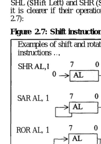
[image:64.507.77.251.263.511.2]SHL, SHR SHL (SHift Left) and SHR (SHift Right) do what they suggest, but it is clearer if their operation is viewed diagrammatically (Figure 2.7):
Figure 2.7: Shift instructions. Examples of shift and rotate instructions . . .
SHR AL,1
SAR AL, 1
ROR AL, 1
RCR AL, 1
The example of SHR moves all bits in AL one place to the right, and a 0 into the most significant bit (MSB). Note that the least significant bit (LSB) goes into the carry flag, CF.
56 Windows Assembly Language h Systems Programming
A limit with the 8088/8086 is that the “count” operand can only be a value of 1 if in immediate mode, as shown in Figure 2.7. If the shift is to be more than 1 bit, a count value must first be moved into CL:
mov cl,3
Sk-X al,cl *shift, 3 bits right.
SAR
ROL, ROR
RCR, RCL
Note that the shift operations can also be on 16-bit (and 32-bit) registers.
SHL does exactly the opposite of SHR, moving zeros into the LSB and the MSB out to the carry flag.
SAR (Shift Arithmetic Right) works like SHR, except it maintains the sign. This is most useful for signed numbers. Refer to Figure 2.7.
ROL (Rotate Left) and ROR (Rotate Right) work similarly to the shift instructions, except what falls out is rotated around back in the other end. Refer to Figure 2.7.
Thus the contents are never lost, but circulate around the register. ROL is the mirror-image of ROR, sending the MSB to the carry flag and back around to the LSB.
RCR (Rotate through Carry Right) and RCL work as per ROR and ROL, except the path of the bits goes through the carry flag. See Figure 2.7.
Code and Data Labels
Labels are potentially an area of enormous confusion, so I review them here very carefully. Labels can be used to mark a “place” in the code or to name some data. They are introduced back on page 41.
Code Labels
In the case of a code label, the syntax is that it should start in column 1 and be suffixed with a colon ” : “, as in this example: . . . .
jmp place1 . . . .
placel: . . . . .
*jumping to somewhere in the program. I
Code labels equate to their address
NEAR and FAR
Procedures
When the assembler assembles the source code, it replaces "jmp placeI" with the operation code for a IMP (jump) instruction, followed by the address place1 as the operand to the instruction. Thus the assembler equates place2 to the offiet it is marking. This is a vital point: the assembler simply replaces all occurrences of place1 in the code with the offset address it equates to.
Normally we would be jumping within the current code segment, so place1 equates to an “offset” from the start of the segment; that is, the IP value of that point in the code. A jump within the segment is called a NEAR jump.
Note that it is also possible to jump between segments, which would be a FAR jump, and I have elaborated on this later in the book.
Another very important point is that any transfer-of-control instruction, such as a IMP or CALL, can have various addressing modes. These modes are encoded by the assembler as part of the instruction operation code. The above IMP example would be what we call immediate addressing, as the operand itself is used as the target address to jump to. Addressing modes have been introduced on page 44.
Another kind of label is the procedure name, as shown here: . . . .
call routine1 . . . .
routine1 PROC
. . . . . r e t
r o u t i n e 1 ENDP
*calling
I a p r o c e d u r e . *the p r o c e d u r e .
Ibody g o e s i n h e r e . *must h a v e e x p l i c i t r e t . I
PROC and Procedures allow you to organize code into structured modules, ENDP that can be called from a main procedure. In some languages they are called subroutines. A function is a special case of a procedure that returns a value via a register. For example, C functions return a value in the AX register or DX:AX register pair (though when writing C programs you don’t know this underlying mechanism of the registers).
58 Windows Assembly Language & Systems Programming
Data Labels
Data labels define constant or variable data, including numerical values, strings, arrays, and pointers.
strl DB V'messagelV,O ;defining an ascii string. varl DW56 ;define word, 16 bits. ptrl DW789
var2 DDO ;define doubleword, 32 bits. aryl DB64 DUP(0) I*array of 64 bytes.
Normally we would think of data as belonging in the data segment, where the code normally expects to access it, but it could just as easily be defined in the code segment, amongst the code, or in the stack. Chapter 4 explores the use of the stack for holding data. Segment override is introduced on page 46.
DB, Define Byte, DW, Define Word, and DD, Define Doubleword, define 8-, 16- and 32-bit data respectively. For example, vad is a 32-bit value of 0. "aryl" shows the use of the DUPlicate directive, which causes the assembler to assemble 64-byte-size values initialized to 0.
Now for the key points: the assembler equates a data label to its address, just as for code labels. However, depending on the instruction, it assembles a non-immediate (i.e., direct, see page 45) addressing mode into the instruction operation code (op-code). This difference is vital.
mov AX,varl *referencing a data label.I mov AX,placel ;referencing a code label.
Major The above examples show the difference. At execution time the
distinction second MOV instruction will move the actual address of place1
between code into a, while the other MOV instruction will use a
and data non-immediate mode, moving not the address varl, but its content. labels Thus, although "MOV ~~,varl" assembled with the address of
varl as the operand to the instruction, at execution-time the instruction looks at the content of that address. Make sure you have grasped this distinction before continuing.
Accessing Data
text string (above), and labelled it “strl”. The assembler equates strl to the starting address of the string.
mov AX, strl ;loads contents.
mov AX, OFFSET strl ;loads address.
OFFSET Unfortunately, because the assembler has assembled the first
override MOV instruction as non-immediate-addressing, the first MOV here would only load the first two ASCII characters (“me”) into AX (two characters are fetched because the destination is AX, which is a 16-bit register).
This is not what we want. We want to load the starting address of the string into AX. What we have to use is an override directive that forces the instruction into an immediate addressing mode. Thus the second example will load the actual operand into AX, which is the required address.
SEG Note too that you can get the segment value where that string is
override stored (which would normally be the data segment), by this override:
mov AX, SEG strl ;load segment address.
OFFSET and SEG only work for static data; that is, data that is defined in the data or code segments. It is possible to have dynamic or automatic data that is created during execution on the stack or heap: getting the addresses of this data involves other techniques, discussed on page 60 (and in Chapters 4 and 5).
Pointers
Data labels can also be pointers. This means that the data content is itself an address. Earlier, I defined “ptrl DW 789”, but the treatment of the content “789” is up to the program. Consider these examples:
c a l l p t r l I-calls address pointed to. c a l l p l a c e 1 ;calls placel.
Immediate “call ptrl” at execution-time will not jump to the ptrl data in
versus non- the data segment - obviously that wouldn’t make sense. No,
immediate since the CALL instruction has assembled as a non-immediate
mode CALL addressing mode, even though the operand of the instruction is the