Article
Enabling Technology and Proof-of-Concept
Evaluation for RAN Architectural Migration toward
5G and Beyond Mobile Systems
Rony Kumer Saha
a,* and Yamazaki Kosuke
bWireless Platform Laboratory, KDDI, Research, Inc., Japan
E-mail: a[email protected] (Corresponding author), b[email protected]
Abstract. In this paper, we address two major issues regarding architectural migration of
radio access network (RAN). Firstly, an overview and explicit interpretation of how different enabling technologies over generations are brought up and coordinated for migration from a distributed, to a centralized, and then to a virtualized RAN for 5G and beyond cellular; and secondly, the proof-of-concept (PoC) evaluation to understand the feasibility of these enabling technologies, are addressed. In doing so, we first give an overview of major enabling technologies and discuss their impact on RAN migration. We then evaluate the PoC of major enabling technologies proposed mainly for 5G CRAN, namely functional split options, TDM-PON systems, and virtualization techniques using a mobile CORD based prototype in LTE systems with ideal fronthauls. PoC experimental results with split options 2 and 5 are presented and compared using TCP and UDP traffic. Experimentally, it is shown that the throughput improvement is significant for TCP as compared to UDP with virtualized BBUs, which are about 30%-40% and 40%-45% higher in mean throughputs respectively in downlink and uplink with split 5 than that with split 2. Finally, we point out the major experimental limitations ofPoC and future research directions.
Keywords: CRAN, migration, proof-of-concept, 5G and beyond, mobile, functional split,
enabling technology, evaluation.
ENGINEERING JOURNAL Volume 23 Issue 3
Received 27 December 2018 Accepted 1 March 2019 Published 31 May 2019
1.
Introduction
1.1. Background and Related Work
In mobile communication systems, ever-increasing user demand of high data rate and diverse service profile, and operator demand of high network capacity and low cost per bit, causes radio access networks (RANs) to evolve considerably over time and generations. Several technologies have been proposed and implemented over generations to address RAN evolution. For example, until existing fourth generation (4G), RAN is considered as distributed where each base station (BS) is integrated with both the baseband and radio functionalities, and both control-plane (CP) and user-plane (UP) are tightly coupled. However, to gain advantages from the cooperation among BSs such as interference management and radio resource scheduling, for example, recently, the baseband unit (BBU) is proposed to be separated from the radio frequency (RF) functionalities, which results in a centralized RAN (CRAN).
Likewise, to overcome the limitation of the coupled C-plane and U-plane (C-/U-plane) from low resource utilization because of serving both C-/U-plane by the same BS, the separation of C-/U-plane is proposed for the fifth generation (5G) mobile networks [1-2]. Further, functional split in CRAN through splitting baseband functionalities of CRAN and leaving some of them from the centralized unit (CU) to the distributed (DU) to reduce high bandwidth in fronthaul (FH) transport network has been proposed [3]. Furthermore, virtualization techniques [4] can help serve multiple traffic sessions. Because of that, on top of the existing CRAN architecture, virtualization techniques can be introduced to satisfy diverse 5G service requirements cheaply and flexibly by employing open source software such as Mobile-Central Office Re-architected as a Datacenter (MCORD) where MCORD is based on CORD that can change existing mobile networks.
Besides, time-division multiplexed passive optical network (TDM-PON) [5] can help reduce the network cost since an optical fiber can be shared at an optical line terminal (OLT) by DUs of a CRAN in multiple small cells. Hence, the realization of CRAN using TDM-PON can help procure access lines cheaply to serve multiple services in order to address the ultra-densification of small cells in 5G networks. Moreover, to achieve ultra-high data rate at the user end (e.g., > 100 Gbps per user) in beyond 5G systems, existing digital radio-over-fiber (DRoF) is not suitable [6] since the bandwidth demand of DRoF system increases with the number of antennas and types and the amount of carrier bandwidth. To address this issue, recently analog transmission over FH has been proposed where instead of digital baseband signals, analog RF signals over FH are transmitted. This transmission technique is termed as analog radio-over-fiber (ARoF).
Numerous experimental studies have been performed to evaluate the feasibility of these aforementioned enabling technologies through proof-of-concept (PoC) evaluation in real time RAN experimental set-ups. In line with so, various experimental studies have been carried out for 5G CRAN by introducing different functional splits [7-8], TDM-PON systems [9], virtualization techniques [10-12], and RAN slicing [13-14]. Furthermore, to address an ultra-high data rate demand per user in beyond 5G cellular, more than 60 Gbps level transmission in the experimental level using ARoF has been reported by now [15]. However, most research works on these major enabling technologies for migration from a distributed to a centralized, and then to a virtualized RAN for 5G and beyond cellular have mainly addressed them separately in terms of either presenting their concepts, applications, performance evaluations, or experimental validations.
Hence, an explicit clarification on how these enabling technologies are brought up and coordinated among each other over generations to enhance RAN architecture further is not obvious in the existing literature. In addition, because of lack of accessories and support systems, PoC evaluation to understand the feasibility of each enabling technology flexibly and cost efficiently in open source software platforms such as MCORD in relevance with RAN enhancement is not immediate. In this paper, we aim to address these two major issues.
1.2. Contribution
software architecture of the proposed virtualized CRAN (vCRAN) based on MCORD in section 4. We then present experimental configurations of the proposed vCRAN with an external FH delay emulator and discuss a number of PoC evaluation scenarios, which concern with BBU configurations, presence or absence of TDM-PON systems, and external delays and packet losses in the FH, as well as the experimental physical setup of vCRAN in section 5. In section 6, PoC experimental results with multiple functional split options, namely 3rd generation partnership project (3GPP) split options 2 and 5, for each evaluation scenario discussed
in section 5 are presented and compared using transmission control protocol (TCP) and user datagram protocol (UDP) traffic in both the uplink (UL) and downlink (DL). Finally, we point out a number of experimental limitations of the PoC evaluation and future research directions in section 7 and conclude the paper in section 8.
1.3. Declaration
This paper is an extended version of the works [16-17] originally presented partly in 2018 IEEE 29th Annual
International Symposium on Personal, Indoor, and Mobile Radio Communications (PIMRC), Bologna, Italy, 9-12, Sep. 2018 [16] and in 2018 IEEE Globecom’18 Workshop on Cloudified Architectures for 5G and beyond Systems, Abu Dhabi, 9-13 Dec. 2018 [17]. Both conference articles [16-17] have been used as the basis of this new journal version, which differs mainly from [16-17] in terms of enhancement of background material, expansion of discussion, and inclusion of new problems and results. More specifically, section 3 is based on [16], sections 4-6 are based on [17], and the remaining sections are newly included. Conference materials used in terms of texts are rewritten whenever necessary, and several figures are reused almost with no modification but citation. Finally, this paper is written as such that readers will find it self-contained, detailed, and more insightful in contrast to its conference versions [16-17].
2.
Overview of Enabling Technologies for RAN Migration toward 5G and Beyond Cellular
In this section, major enabling technologies employed to migrate RAN towards 5G and beyond are discussed briefly.
2.1. Centralization of Radio Access Network
The envisaged user demands, including high data rate, diverse service profile, and seamless quality of service (QoS) experienced between indoor and outdoor environments, for next-generation mobile networks (NGMN) (e.g., 5G and beyond mobile networks) cause to rethink whether or not to continue with the existing decentralized network architectures in 4G cellular that leads to scale small cell (SC) base stations (SCBSs) with the number of user equipments (UEs) and the traffic volume per unit area [18]. These cause to increase the network operational cost and generate severe inter-cell interference, for example, and necessitates considering centralized or cloud access network architectures. In CRAN, because of the centralized processing feature, the radio resource scheduling can be benefitted from efficient interference management, and radio resources of different BSs can be shared with each other whenever necessary. A pool of BBUs with centralized processors is separated from the respective DUs and is located in a CU by a link called FH in CRAN [19]. An FH can be ideal and non-ideal based on its bandwidth and latency demands, which operates on protocols such as common public radio interface (CPRI).
2.2. CRAN Functional Split Architecture and Deployment Scenario
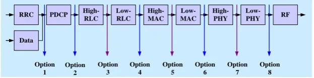
Figure 1 shows the recommended functional split options between the CU and DU by 3GPP for evolved universal terrestrial radio access (E-UTRA). As shown in the figure, based on how much functionalities we would leave between the CU and DU, there are 8 functional split options leveled as 1, 2,…, 8 have been proposed by the 3GPP for CRAN. As split options are chosen from a higher to a lower layer, e.g. from split 2 to split 8, the demand of the FH bandwidth requirement increases, i.e. the lowest with split 2 and the highest with split 8. Further, split options 6 and above demand tight latency requirement, whereas split options 4 and below demand loose latency requirement.
Fig. 1. Proposed 3GPP functional split options in CRAN for downlink [3].
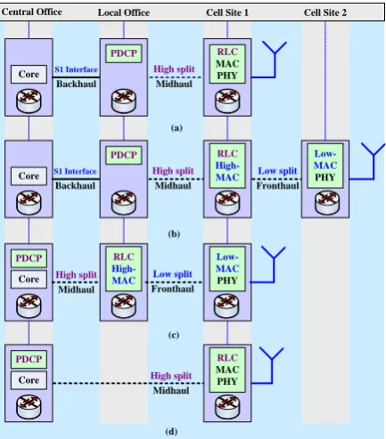
It is important to note that based on the split option and the number of functional splits considered in a CRAN, a number of network deployments for 5G and beyond can be made. For instance, Fig. 2 shows a number of deployment scenarios based on the 3GPP functional split options 2 (i.e., packet data converge protocol (PDCP)/radio link control (RLC)) and 5 (i.e., split medium access control (MAC)) when considering either a single or multiple splits in a CRAN. Hence, deployments in Figs. 2(a) and 2(d) consider only a single functional split option, i.e. split option 2; whereas multiple split options, namely split options 2 and 5 are considered for the deployments in Figs. 2(b) and 2(c). Note that in Fig. 2, the core network is considered to locate at the central office. Furthermore, for upper layer splits such as split 2, upper layer functionalities, e.g. PDCP, can be located either at the central office as shown in Figs. 2(c) and 2(d) or a local office as shown in Figs. 2(a) and 2(b).
Note that these network deployments with splits 2 and 5 in Fig. 2 can also be carried out similarly with other 3GPP functional split options. Also, for multiple split options, the link existing for the low split is called FH, and the link existing for the high split is called midhaul. However, for a single split option not having upper layer functionalities resided at the core network, the link existing for such a split is called backhaul as shown in Figs. 2(a) and 2(b). Since each of these split options has a direct impact on the performance of CRAN, namely the reduction in cost and simplicity of DUs, it allows flexibility to network operators to find appropriate functional split options compliant to a diverse set of 5G service requirements.
2.3. Control-plane and User-plane Decoupled Architecture
5G and beyond cellular networks will see increasing use of very dense deployments of BSs where user terminals will be able to connect to multiple transmission points simultaneously. Hence, it would be favorable and beneficial for the next generation radio access terminals (RATs) to base the architecture on the separation of CP and UP functions. This separation would imply to allocate specific CP and UP functions between different nodes. There are two basic architectures identified for UP-CP splitting, namely a flat UP-CP separation architecture where there is a clear separation of UP-CP functions same as the separation of LTE functions, and a hierarchical UP-CP separation architecture where UP and CP are not separated for the functions used in LTE.
In existing mobile networks, the tight coupling of C-/U-plane limits the flexibility in network operation and performance management, e.g. keeps switching the transmit power of an SCBS on even though no user data is available to communicate through the network. This results in poor resource utilization by consuming unnecessary power. Hence, as mentioned earlier, following the flat UP-CP separation architecture, the CP and UP are decoupled such that UP BSs can be managed for their transmit powers based on traffic demands of their users. Such a decoupled CP and UP architecture is termed as CP and UP decoupled architecture (CUDA) [1-2]. The CUDA can address the bandwidth and latency limitations of a FH in CRAN [21] such that all control signaling and system broadcasting data can be delivered to UEs by high power nodes, i.e.
RRC PDCP High-RLC
Low-RLC
High-MAC
Low-MAC
High-PHY
Low-PHY RF
Data
Option 2
Option 3
Option 4
Option 5
Option 6
Option 7
Option 8 Option
macrocell BSs (MCBSs), and high-speed user data services to UEs by low power nodes, i.e. SCBSs such as RRHs, which can be switched on and off based on the active data traffic requests. Hence, MCBSs are incorporated into traditional CRANs by decoupling the CP and UP. This architecture is termed as heterogeneous CRAN (HCRAN) [22].
Fig. 2. 5G and beyond cellular networks deployment scenarios with functional split options 2 and 5. When the PDCP is located away from the central office: (a) single split (3GPP PDCP/RLC split) and (b) dual-split (3GPP PDCP/RLC high split and intra MAC low split). However, when the PDCP is located at the central office: (c) dual-split (3GPP PDCP/RLC high split and Intra MAC low split and (d) single split (3GPP PDCP/RLC split).
2.4. CRAN Virtualization and Slicing Mechanism
5G and beyond mobile networks need to be highly flexible to support a diverse set of demands and service requirements. To address such high flexibility, realizing an end-to-end slicing through network core to RAN can play a crucial role. Further, to minimize network latency, the best location to install equipment of BSs is the local office such that with an increase in latency, more BSs can be aggregated. But, installing equipment at local offices is constrained by the limitation of space and power supplied to them. On the contrary, to reduce capital expenditure (CAPEX) and operational expenditure (OPEX) by aggregating BSs, the best location to install equipment is the regional central office. To address such issues, RAN virtualization and RAN slicing can help by optimizing the network location to install equipment under constraints, including space, CAPEX, and OPEX.
In a vCRAN, all hardware are interconnected and interacted via backhaul networks and managed by XOS orchestrators. All functionalities of RAN (from layer 1 to layer 3) and evolved packet core (EPC) are virtualized as virtual network functions (VNFs) that move network functions of both RAN and EPC out of dedicated hardware devices into software and run on one or more virtual machines (VMs) on top of the hardware. OpenStack provides this software with an open-source software platform for cloud computing. Both RAN and EPC controllers run on open network operating system (ONOS) that provides the CP with a software-defined network (SDN) once employed. The whole network is sliced based on service (e.g., Internet-of-things (IoT), Enhanced mobile broadband (eMBB), and ultra-reliable low latency communications (URLLC) requirements and XOS helps combine tasks into workflows so that the provisioning and management of various components and their associated resources can be automated.
Core
Core PDCP
Core PDCP
PDCP
Backhaul
S1 Interface
Midhaul High split
RLC MAC PHY
Core
PDCP
Backhaul
S1 Interface
Midhaul High split
RLC High-MAC
Fronthaul Low split
Low-MAC PHY
Midhaul High split
Fronthaul Low split RLC High-MAC
Low-MAC PHY
Midhaul High split
RLC MAC PHY
Central Office Local Office Cell Site 1 Cell Site 2
(a)
(b)
(c)
[image:5.595.190.407.140.387.2]2.5. TDM-PON Systems in CRAN FH
Passive optical network (PON) technology is an economical candidate to deploy small cells such as RRHs densely to boost the capacity of 5G and beyond mobile networks. The most widely used multiplexing technique in PON is time-division multiplexing (TDM) since optical components can be kept relatively simple and cheap. Because, an optical fiber can be shared at an OLT by RRHs, TDM-PON can help reduce the network cost. Moreover, TDM-PON has the property that decreases the network cost as the number of subscribers increases. Hence, the realizations of CRAN using TDM-PON can help procure access lines cheaply, resulting in a cost-effective mobile FH (MFH), in order to address the ultra-densification of small cells in 5G and beyond networks. It is to be noted that for a time-division duplex (TDD) system, the wireless bandwidth for a UE is allocated flexibly in the same frequency band. A TDD system uses different wavelengths in upstream and downstream. Further, neighboring RRHs in a TDD system are time synchronized that use the same wireless frame index in order to avoid the signal collision. This is because the total fiber length from one optical network unit (ONU) to the OLT may differ from the other.
2.6. Dynamic Placement of CU and Core Network
Unlike 4G where the core network is located statically at the central office, the placement of core network functionalities in 5G and beyond needs to be dynamic in order to adapt with a diverse set of service requirements. For example, low latency services require the core network, i.e. EPC, to move ahead toward the radio interface such that the core network functions can be located at the local office. Similarly, when considering splitting of the CP and UP of the EPC, the locations of CP and UP also vary with service requirements.
Since different functional split options are constrained from different latency and bandwidth requirements, the placement of the CU from DUs also varies. For instance, lower layer functional split options are susceptible to the tight latency requirement, resulting in the CU needs to be placed at the local office instead of the central office. On the other hand, the latency requirement can be relaxed for services such as non-real time IoT so that the CU could be located far away from a DU, e.g. at the central office. Such dynamic functional splits in FH based on service requirements demand virtualization of servers so that different functional splits can be placed and configured at different locations (e.g., central office and local office). Hence, as explained before, virtualization of network functionalities at the CU and Dus can help manage such dynamic switching between virtual servers at different locations according to service requirements.
2.7. Analog and Digital FH
The FH transport network in CRAN has a significant impact on performances of 5G and beyond cellular networks. In current CRAN data is transported over FH using digital transmission techniques. If the optical fiber is used as the physical transport media for FH, and the baseband signal is transmitted by sampling over FH, such type of transmission technique is referred to as DRoF. However, currently used transmission protocol such as CPRI in CRAN FH using DRoF cannot be able to support FH data rate of 5G and beyond networks. This is because, CPRI is a constant rate transmission technique, which suffers from high fixed FH data rate (e.g., an FH data rate of about 16 times as that of a user data rate is required [6]) and latency requirements with an increase in user data rate. Though such constraint can be overcome by baseband functional splitting between the CU and DU as explained earlier, the expected data rate per user particularly for beyond 5G systems cannot be addressed since the bandwidth demand of a DRoF system increases with the number of antennas and types and the amount of carrier bandwidth.
3.
RAN Architectural Migration toward 5G and beyond Cellular
In this section, we present RAN architectural migration from 4G to the upcoming 5G and beyond mobile networks by pointing out how the enabling technologies discussed in the previous section are employed over time and generations to enhance the capabilities of RAN in order to address both operators’ and users’ demands. Note that since we are interested in RAN evolution from now and onwards, the following discussion on RAN architectural migration considers the existing 4G cellular system as a baseline.
3.1. 4G Mobile RAN
Figure 3 shows network architectural migration from the current 4G to the prospective 5G and beyond mobile networks. Existing 4G RAN is distributed where each BS is integrated with both the baseband and radio functionalities (Fig. 3(a)). Recently, centralization of baseband functionalities has been implemented to gain advantages from centralized scheduling and cooperation among BSs by separating the BBU from the RF functionalities, resulting in a CRAN (Fig. 3(b)). However, because of insufficient access line capacity, the LTE system cannot become able to serve required high user throughput demand. This insufficient capacity arises from the fact that existing CRAN uses CPRI protocol for the FH to transport data between the BBU and RRH. CPRI is based on digital transmission of baseband signals, which costs about 16 times a user data rate [6] to transport data over the FH.
3.2. 5G Mobile RAN- Phase 1
To address the aforementioned problem of requiring the excessive access line capacity as compared to a user data rate, some of the CRAN functionalities, particularly the lower layer ones, have been proposed to move from the BBU to the radio access node, i.e. RRH. Further, the core network of 4G has been proposed to split into CP and UP for flexibility in network management. Furthermore, to address such issues as reducing the processing delay in order to serve mission-critical services, some of the applications are moved from the application servers to the access network for fast processing (Fig. 3(c)). It is to be noted that in phase 1 of 5G, several remote radio units (RRUs) can be aggregated to a central unit, also termed as radio access unit (RAU), that works as a point of local aggregation, i.e. aggregation unit (AU), of baseband data from several UEs through RAUs. AU incorporates all the baseband functionalities in CRAN as shown in Fig. 3(b). The functionalities of UEs to control baseband data can be centralized and located alongside the mobile-edge computing (MEC) and UP of the core network as shown in Fig. 3(c). MEC, CP, and UP of core networks and CU, all can be implemented in commercial off-the-shelf (COTS) servers, whereas AUs are implemented partially in COTS server. Also, 4G networks operate on below 6 GHz irrespective of the centralization of RAN. However, 5G phase 1 will operate on above 6 GHz or mmWave bands in addition.
3.3. 5G Mobile RAN- Phase 2
Since 5G is expected to serve services with diverse requirements, in terms of, for example, bandwidth and latency, in order to serve each service type, a set of physical BSs may need to be set. This can be addressed by introducing virtualization technique to CRAN such that by virtualizing functionalities of each CRAN, multiple VMs can be generated in the same physical hardware for the BBU and the RRH. Hence, instead of the physical BBU, multiple VMs, i.e. virtualized BBUs (vBBUs), can serve multiple types of services simultaneously through slicing and moving certain RAN functionalities appropriately from any vBBUs to its RRH corresponding to each service requirement. This results in as well a reduction in cost from the physical set-up and an improvement in flexibility by changing the size and the number of VM instances per physical server using the software. Figure 3 also shows the network architectural migration from phase 1 to phase 2. Phase 2 differs mainly from phase 1 by the fact that virtualization of all the functionalities of RAN, i.e. RAN slicing, is considered for any functional split options in CRAN. In Phase 2, protocol stacks as a central unit are considered to place anywhere according to service requirements on a cloud platform.
access of a large number of machine-type devices of the envisioned 5G IoT scenario. mMTC based services include sensing and metering [26]. Because of a diverse set of requirements from one to another, each service category imposes a diverse set of requirements on networks to support it, and the traditional closed-form solutions, i.e. one network architecture configuration/hardware for all, is no more effective. This results in adaptive and automatic architectural reconfiguration using the same hardware for a diverse set of quality of services simultaneously by slicing the same hardware employing virtualization techniques.
As shown in Fig. 3(d) for 5G phase 2, the phase 1 architecture of 5G networks changes with a change in use case category, i.e. eMBB, voice, mMTC, and URLLC. For example in order to manage many transmission and reception points (TRPs) for beamforming at a high frequency to support eMBB, layer 2 (L2)/layer 3 (L3) CU is placed at the local office, whereas L1 functionalities are left with the AU. Further to reduce U-plane traffic and pre-caching spot services using mmWave, U-plane of 5G core and MEC reside at the local office as well. However, when serving eMBB at low frequency, to overcome inter-cell interference effect and to make AUs simple with least functionalities, a tight interworking between neighbor cells are supported locally by moving all L1, L2 and L3 functionalities of the CU to the local office in order to impose coordinated multi-point (CoMP) techniques on nearby TRPs to reduce interference effect. Like operating at high frequencies, U-plane of core networks when operating at low frequency is placed at the local office to reduce network overhead and the C-plane of the core network is left at the central office.
Further, because mMTC services are delay tolerant, CU does not need to place at the edge network. Rather, CU can be placed only with L3 functionalities at the central office to get the advantage of high FH delay by leaving L2 and L1 functionalities to the edge nodes to reduce transport overhead and minimize cost by centralizing equipment. Along with CU, both CP and UP of the core network are also placed at the central office. Furthermore, to support URLLC services, UP of 5G core networks and MEC can be considered at the local office to address low latency. CU with L1 to L3 functionalities is placed at the local office to address any redundant links and its management for high reliability. Note that for conventional voice services, because of centralized Internet Protocol (IP)-based multimedia services (IMS), CU is placed at the central office. Further, both L1 and L2 functionalities are left with the access unit to address stringent delay requirement from real-time voice communications. Hence, to create a flexible and scalable 5G network, virtualized RAN (vRAN)/ RAN slicing is carried out in phase 2. Like 5G phase 1, 5G phase 2 will operate as well on above 6 GHz or mmWave bands.
3.4. Post 5G Mobile RAN
However, serving multiple services simultaneously for each UE demands high data rate per user in the wireless access interface between an RRH and a UE, which causes to increase further the access line capacity. Such a situation can be addressed by providing analog radio transmission over fiber instead of CPRI based digital transmission so that electrical signals can be converted directly to their optical equivalents without employing any digital conversions. Note that the chromatic dispersion effect because of optical fiber transmissions in analog transmission systems, the effective bandwidth at the receiving end is reduced. This can be overcome by employing parallel transmitter architecture utilizing both intensity modulation (IM) and phase modulation (PM) [6] by taking advantage of their complementary relationship between IM and PM to provide a flat response over a high-frequency bandwidth by covering intermediate frequency from dispersion-induced RF power fading effect. In such situation, UEs are served by small aperture antennas within a short distance to provide for example more than a hundred of Gbps data rate per UE using a high capacity ARoF line over a long distance, expected for post 5G by 2030 (Fig. 3(e)). Note that in research level, more than 60 Gbps level transmission using ARoF has been reported by now.
4.
A Prototype of MCORD Based vCRAN Software Architecture
4.1. Head Node Virtual Machine
All the head node services are running inside a VM using vagrant on top of libvirt/qemu/kvm hypervisor. The operating system (OS) running in the VM is Ubuntu 14.04. The VM is named as prod. The original ARM64 porting of MCORD 2.0 is based on CORD-in-a-Box concept, under which the whole MCORD system is running in one machine through many VMs. Compute nodes are moved to physical machines for better performance and avoiding nested VMs. But, head node services remain in a VM.
4.2. Management Network
The management network is a vagrant created VM. All the services inside prod are connected to the management network, and all the hosts connected to it have their IP address, assigned through the Dynamic Host Configuration Protocol (DHCP) server. The DHCP server is running inside prod. The Domain Name System (DNS) server running also inside prod resolves hostnames of all machines. The head node’s physical network interface eth1 is added to the virtual bridge, represented as br in the diagram. The eth1 interfaces of all the compute nodes are also connected to the management network through a management network switch.
4.3. Metal-as-a-Service
Metal-as-a-Service (MaaS) is open source software. The MaaS service is used to automatically setting up and provisioning new compute nodes. Both compute nodes 1 and 2 are set up and provisioned by the MaaS. There are several Docker containers running inside prod for the MaaS to provide functions such as adding IP addresses assigned by the DHCP server to any compute nodes as a new record in the DNS server, in addition to adding newly added compute nodes to ONOS/cordvtn for the connections and flows of Open vSwitch (OvS).
4.4. OpenStack Kilo
OpenStack Kilo, the 11th release of OpenStack, is used in setting up CORD. OpenStack services deployed in
CORD are ceilometer, keystone, rabbitmq-server, 59agios, mongodb, openstack-dashboard, neutron-api, nova-cloud-controller, glance, and percona-cluster. Each service is running as a lightweight lxd container with a full filesystem and IP address. OpenStack services are deployed by juju software.
4.5. XOS
XOS is the core of the CORD system. The input to the XOS is Topology and Orchestration Specification for Cloud Applications (TOSCA) yaml file to describe all services and networks. XOS converts all this information to the necessary steps in order to configure other parts of the CORD system. XOS provides web Graphical User Interface (GUI) to most functions, e.g. checking status. XOS services are running as multiple docker containers inside prod. XOS creates all the networks inside neutron described in TOSCA profile. Each network type is synchronized to ONOS-CORD/cordvtn application in order to set proper flows for the OvSs.
4.6. ONOS CORD and Fabric
4.7. vBBU/vEPC and FH Switch/PON
The vbbu slice is defined in MCORD TOSCA inside which virtualized BBU1 (vBBU1) and vBBU2 instances are created. vBBU1 uses virtual local area network (VLAN) tag 100, and vBBU2 uses VLAN tag 200 to transmit traffic to respective RRHs. However, virtualized evolved packet core (vEPC) and media server instances are created inside the vmme slice defined also in MCORD TOSCA. The FH switch is configured to allow 802.11Q VLAN tagged traffic to transfer from compute node 1 to the OLT-PON with a VLAN tag stripped for each vBBU. When the traffic comes from the OLT-PON, it tags the traffic with the matched VLAN tag either 100 or 200 based on the packet’s source MAC address.
Fig. 3. Network architectural migration from the current 4G to the prospective 5G and beyond mobile networks [16].
5.
Experimental Configuration, Evaluation Scenario and Physical Set-up of vCRAN
In this section, we now present the experimental configuration, evaluation scenario, and the physical set-up of the proposed vCRAN for the PoC evaluation.
Figure 5 shows experimental configurations for the evaluation of the PoC for the proposed vCRAN with an external FH delay emulator. We carry out PoC evaluations in two cases, namely, in case 1, a TDM-PON is not considered in the FH (i.e., only Ethernet fabric is present) and in case 2 a TDM-PON is considered between the FH switch and RRHs. A real BBU along with a real EPC and two vBBUs are created in compute node 1. In compute node 2, a vEPC and a virtualized application server (vAPP) are created. We consider mainly three PoC evaluation scenarios as follows, which are configured by killing either the real BBU or any vBBUs.
(1) only the real BBU operates
(2) both vBBU 1 and vBBU 2 operate simultaneously (3) either vBBU 1 or vBBU 2 operates
An external delay emulator is inserted on the FH such that it can be either common to both vBBUs in compute node 1 for scenario 2 or applied to any vBBUs for scenario 3 or the real BBU for scenario 1. To evaluate the impact of the TDM-PON, a TDM-PON is also inserted on the FH for scenario 2. Both TCP and UDP traffic are evaluated for each of the above evaluation scenarios in UL and DL. Data packets are generated using the iperf command in the UE for UL, and either the EPC or vEPC for DL. Figure 6 shows
4G Core BBU 4G UE Metro Network Access Network (a) Application Servers RRH Backhaul In te rn et 4G Core 4G UE Metro Network Access Network Application Servers (b) BBU RRH (RF) Aggregation Unit (RF plus Functions corresponding to 3GPP split options)
5G UE Metro Network Access Network 5G Core (C-plane) Application Servers (c) B as eb an d
BBU Functional Split (e.g., 3GPP split options from 1 to 8)
R A U R R U R R U R R U S ep a ra ti o n o p ti o n
Implemented partially in COTS Server Fronthaul Mobile Edge Computing 5G Core (U-plane) Central Unit Implemented in COTS Server Backhaul D ec o u p li n g C -p la n e an d U -p la n e C-plane U-plane Regional Applications or Cache In te rn et Implemented in COTS Server 5G Core (C-plane) Mobile Edge Computing 5G Core (U-plane) Central Unit (L2/L3) Aggregation Unit (RF/L1) 5G UE Metro Network Access Network eMBB (High Frequency) Aggregation Unit (RF/L1/L2) 5G UE Metro Network Access Network mMTC 5G Core (C-plane) Mobile Edge Computing 5G Core (U-plane) Central Unit (L1/L2/L3) Aggregation Unit (RF) 5G UE Metro Network Access Network URLLC Aggregation Unit (RF/L1/L2) 5G UE Metro Network Access Network Voice IMS 5G Core (U-plane) Central Unit (L3) 5G Core (C-plane) Application Servers Application Servers Application Servers 5G Core (U-plane) Central Unit (L3) 5G Core (C-plane) Internet or Dedicated Networks
5G Core (C-plane) Mobile Edge Computing 5G Core (U-plane) Central Unit (L1/L2/L3) Aggregation Unit (RF) 5G UE Metro Network Access Network eMBB (Low Frequency) Application Servers (d) Central office Local office Cell site Device Service The Internet In te rn et Post 5G Core (C-plane) Post 5G UE Metro Network Access Network (e) BBU Antenna End In te rn et Post 5G Core (U-plane) RRH (RF) ARoF DRoF DRoF DRoF DRoF DRoF DRoF DRoF
Post 5G Services (>100 Gbps)
4G (DRAN) 4G (CRAN) 5G (Phase 1) 5G (Phase 2): Full 5G Network and Network Slicing Post 5G
Application Servers
Now 2020 2025 2030
[image:10.595.71.527.204.451.2]the physical set-up for the configurations shown in Fig. 5. We use three generic servers termed as head node, compute node 1, and compute node 2. Recall that the head node incorporates MCORD to control functionalities of vCRAN. The real BBU is virtualized with the RAN functionalities corresponding to the functional splits 2 and 5. Two virtualized BBUs, namely vBBU 1 and vBBU 2, are generated in compute node 1; whereas a vAPP and a vEPC are generated in compute node 2. Each vBBU is logically connected to an RRH and is separated from the other when running simultaneously using a distinct VLAN tag in their respective transmitted packets over the FH so that packets of any vBBUs correspond to only the preconfigured RRH for any functional splits.
In the following, we discuss the physical connectivity flow between network equipment using numeric values as shown in Fig. 6. Compute node 1 and compute node 2 are connected to the FH switch (points 1 and 2). The FH switch is connected to the Ethernet port 1 of the delay emulator when the emulator is common to both vBBUs (point 3). The Ethernet port 2 of the emulator is then connected to the OLT of the TDM-PON (point 4), the output of which is then inputted to a splitter via an optical fiber (point 5). Each of the three output ports of the splitter (point 6) is connected to an ONU via an optical fiber link (point 7). Each ONU is then connected to an RRH (point 8). Each RRH is connected via two RF cables to a universal serial bus (USB) Dongle (point 9) inserted on a personal computer (PC) that jointly operate as a UE (point 10).
In DL, either TCP or UDP data packets are generated using iperf in the vEPC, which then pass through their preconfigured vBBU. From compute node 1, packets then follow the path of the physical connectivity flow described above to reach its UE. Similar to DL, TCP and UDP packets are generated at each UE using iperf in UL, which then follow exactly the same but a reverse transmission path to that of DL to reach the vEPC. However, for the real BBU, data packets are generated using iperf in the EPC and pass through the real BBU in DL. From the real BBU to a UE, packets follow the same physical connectivity flow as above. Like vBBUs in UL, packets are also generated in a UE using iperf in UL and follow the same but reverse transmission path to that of DL to reach the EPC through the real BBU. In Table 1, system and radio specifications and parameters for the PoC are given.
Fig. 4. A prototype of the software architecture of the proposed MCORD based vCRAN [17].
Head Node VM prod juju ceilometer glance keystone percona-cluster nagios neutron-api nova-cloud-controller openstack-dashboard rabbitmq-server mongodb lxd containers config-generator ip-allocator harvester provisioner MaaS docker containers MaaS Service ONOS CORD cordvtn XOS sync sy n c sy n c DHCP Server DNS Server ONOS Fabric br Flows Flows
Compute Node 1
vBBU 2 vBBU 1
OvS
Compute Node 2
Media Server vEPC
OvS
Spine/leaf switch control
[image:11.595.67.528.414.651.2]Fig. 5. Experimental configurations of the proposed vCRAN with an external FH delay emulator for the PoC evaluation; (a) case 1: when the TDM-PON system exists between the FH switch and RRHs; (b) case 2: when the fabric exists between the FH switch and RRHs. The delay emulator is connected between points a and b when it is common to both vBBUs, and between points c and when it is present for a single vBBU, i.e. vBBU1 [17].
Fig. 6. The physical set-up of the vCRAN for the PoC evaluation. Numeric values in the figure represent the flow of connectivity in DL, for example [17].
Fronthaul Switch
Compote Node 1 Management Switch Controller (Head Node)
b
L2 Switch
Fronthaul
Fabric
c d e
a
OLT
Fronthaul
ONU 1
ONU 2
ONU 3
Splitter
TDM-PON System
a c
d e RRH 1 RRH 2 RRH 3 UE 1
UE 2 UE 3
Delay Emulator a b
Compote Node 2
vBBU1
vBBU2
BBU EPC
vEPC vAPP c
d e
Delay Emulator
c c
[image:12.595.72.530.79.246.2] [image:12.595.71.527.332.673.2]6.
PoC Experimental Results with Multiple Functional Splits of vCRAN
In this section, we present PoC experimental results with functional split options 2 and 5 for each of the three evaluation scenarios discussed in section 5. Impact of virtualization of physical BBUs as well as consideration of TDM-PON system, external delay, and packet loss in the FH is evaluated for each functional split option and compared their performances with each other using both TCP and UDP traffic in both UL and DL.
6.1. Maximum Transmit Bandwidth for TCP and UDP Traffic
In order to set the default maximum transmit bandwidth for TCP and UDP in both DL and UL, we first investigate how the received throughput is affected by the change of the transmit bandwidth. Figure 7 shows the received throughput response for a single vBBU without considering any TDM-PON systems as well as external delays in the FH with split 2. From Fig. 7, it can be found that the received UDP throughputs in both UL and DL increase proportionately up to the transmit bandwidth of 20 Mbps and 70 Mbps respectively, which remain invariant for any higher values than these ones. Since TCP also shows similar trends as that of UDP, we set the transmit bandwidths of 70 Mbps in the DL and 20 Mbps in the UL for both the UDP and TCP traffic. Similarly, with split 5, it is found that the transmission bandwidths are upper limited by 30 Mbps in DL and 8 Mbps in UL for both the UDP and TCP with split 5. Note that the reduction in maximum transmit bandwidth when operating with split 5 is about half of that when operating with split 2. This is due to system-specific implementation issues concerning mainly how the MAC scheduler is designed, described in the following.
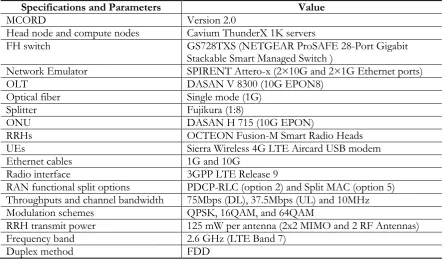
Table 1. System and radio specifications and parameters.
Specifications and Parameters Value
MCORD Version 2.0
Head node and compute nodes Cavium ThunderX 1K servers
FH switch GS728TXS (NETGEAR ProSAFE 28-Port Gigabit
Stackable Smart Managed Switch )
Network Emulator SPIRENT Attero-x (2×10G and 2×1G Ethernet ports)
OLT DASAN V 8300 (10G EPON8)
Optical fiber Single mode (1G)
Splitter Fujikura (1:8)
ONU DASAN H 715 (10G EPON)
RRHs OCTEON Fusion-M Smart Radio Heads
UEs Sierra Wireless 4G LTE Aircard USB modem
Ethernet cables 1G and 10G
Radio interface 3GPP LTE Release 9
RAN functional split options PDCP-RLC (option 2) and Split MAC (option 5) Throughputs and channel bandwidth 75Mbps (DL), 37.5Mbps (UL) and 10MHz
Modulation schemes QPSK, 16QAM, and 64QAM
RRH transmit power 125 mW per antenna (2x2 MIMO and 2 RF Antennas)
Frequency band 2.6 GHz (LTE Band 7)
[image:13.595.76.523.391.651.2]Fig. 7. Impacts of change in transmit bandwidth on DL and UL throughputs of UDP without considering TDM-PON systems and delay with split 2 [17].
With split 5, the resource scheduler is centralized in contrast to that in split 2. The scheduler is implemented based on the principle of n+k+2 where n denotes the subframe to schedule for transmission,
k denotes roundtrip FH delay, and the number 2 denotes time in ms for processing data at the physical layer
and over-the-air (OTA) transmission. Hence, the scheduler schedules transmission for subframe k+2 during subframe n. With split 2, k=0 (Fig. 8(a)) because of no FH between the scheduler and physical layer (PHY)/RF such that hybrid automatic repeat request (HARQ) can be accomplished in every 8 ms (for the synchronous mechanism) to schedule packets for a UE over each 8 ms (i.e., 8 ms time is required between any retransmissions or a new transmission for the same HARQ process). However, with split 5, k=2 (Fig. 8(b)) such that there is an additional 2 ms round trip fronthaul delay, which causes the scheduler to wait for this additional delay. It results in limiting the earliest re-transmission time and hence reducing per UE throughput to about half of that with split 2.
Fig. 8. HARQ mechanisms in the vCRAN; (a) with split 2; (b) split 5 [17].
50 60 70 80
50 55 60 65 70
Transmit Bandwidth (Mbps)
D
ow
nl
ink
T
hr
ou
gh
pu
t
(M
bp
s)
vBBU (UDP)
5 10 15 20 25 30
5 10 15 20
Transmit Bandwidth (Mbps)
U
pl
ink
T
hr
ou
gh
pu
t
(M
bp
s)
vBBU (UDP)
(b) (a)
Subframe (ms) BBU/vBBU
8 HARQ 8 HARQ
UE
Re-transmission/ new transmission
ACK/NACK
(b) Fronthaul
0 1 2 3 4 5 6 7 8 9 10 11 12 13 14 15 16 17
Subframe (ms) RRH
8 HARQ 8 HARQ
UE
Re-transmission/ new transmission
ACK/NACK
Re-transmission/ new transmission
ACK/NACK
(a)
[image:14.595.139.458.80.230.2] [image:14.595.88.511.425.666.2]6.2. PoC Evaluation with Functional Split Option 2
6.2.1. Impact of virtualization of physical BBUs
From Figs. 9(a)-(b), it can be found that the received DL throughput of UDP does not deviate considerably from the physical system when it is virtualized, irrespective of the number of vBBUs created in the physical system. Like UDP, the impact of virtualization of BBUs is also negligible on TCP throughputs when a single vBBU runs in the physical system. However, a noticeable adverse impact is observed when multiple vBBUs run simultaneously. Particularly, as shown in Fig. 9(b), approximately 30% lower in mean throughput for both vBBUs than that (i.e., 62 Mbps) of the real BBU is observed. Further, it is to be noted that whether or not the physical system is virtualized, the mean TCP throughput is always lower than that of UDP. This can be explained to happen because of the inherent congestion avoidance mechanism existing in state-full TCP in contrary to the constant transmit rate, stateless UDP. Figures 10(c)-7(d) shows UL mean throughput responses when two vBBUs run simultaneously. From these figures, it can be observed that the UL also shows similar throughput responses as that of DL for both UDP and TCP. Notably, the TCP UL mean throughput with both vBBUs is about half of the maximum transmit bandwidth of 20 Mbps. The UDP UL throughput, however, remains unaffected around 20 Mbps.
6.2.2. Impact of TDM-PON system on the FH
From Fig. 10, it can be found that inserting a TDM-PON system on the FH helps improve both UL and DL mean throughputs of TCP and UDP. More specifically, the improvement in throughput is noticeable more in UL than in DL for both TCP and UDP, which could be because of the dynamic resource scheduler at the TDM-PON that allocates radio resources to UEs of respective vBBUs to schedule their traffic such that the aggregate UL throughput can be maximized. Hence, the TDM-PON system in the FH is recommended to improve UL throughput responses of both TCP and UDP. Further, the gain in TCP throughput from using the TDM-PON system in both UL and DL is significantly higher than its counterpart UDP because of the reliable data transmission feature of TCP that helps retransmitted packets of TCP gets benefited from dynamic resource scheduling in the TDM-PON system.
6.2.3. Impact of external delay on the FH
From Fig. 11, it can be found that UDP throughputs with an increase in FH delay decrease near linearly in DL and remain almost invariant in UL for the real BBU. However, when the BBU is virtualized, these UDP throughputs vary about negative exponentially with FH delay in both UL and DL. On the other hand, TCP throughputs follow a near negative exponential decrease with an increase in delay irrespective of whether or not the physical BBU is virtualized in both UL and DL as shown in Figs. 11(a)-11(b). Also, if multiple vBBUs run in parallel, irrespective of whether a delay is imposed on all vBBUs (Figs. 12(a)-12(b)) or any vBBUs (Figs. 12(c)-12(d)), the similar response in TCP throughputs is found.
Fig. 9. Impact of virtualization; (a) when vBBU1 or vBBU 2 operates; (b) when both vBBUs operate [17].
Fig. 10. Mean throughput responses of UDP and TCP in UL and DL with and without inserting a TDM-PON system on the FH with split 2 [17].
10 35 60 85 100
54 56 58 60 62 64 66 68 70 Time (s) T h ro u g h p u t (Mb p s)
BBU with UDP vBBU1 with UDP vBBU2 with UDP BBU with TCP vBBU1 with TCP vBBU2 with TCP
10 35 60 85 100
40 45 50 55 60 65 70 Time (s) T h ro u g h p u t (Mb p s)
BBU with UDP vBBU1 with UDP vBBU2 with UDP BBU with TCP vBBU1 with TCP vBBU2 with TCP
(b) (a)
vBBU1 without PON vBBU2 without PON vBBU1 with PON vBBU2 with PON 42 43 44 45 M e a n T C P D o w n li n k T h ro u g h p u t (M b p s)
vBBU1 without PON vBBU2 without PON vBBU1 with PON vBBU2 with PON 19.6 19.8 20 M e a n U D P U p li n k T h ro u g h p u t (M b p s)
vBBU1 without PON vBBU2 without PON vBBU1 with PON vBBU2 with PON 9 9.5 10 M e a n T C P U p li n k T h ro u g h p u t (M b p s)
[image:16.595.143.458.291.638.2]Fig. 11. Impact of change in external FH delay on TCP and UDP throughputs for real BBU and a vBBU without any TDM-PON systems with split 2 [17].
6.3. PoC Evaluation with Functional Split Option 5
6.3.1. Impact of virtualization of physical BBUs
From Fig. 13, it can be found that in DL, the throughput of TCP traffic gets affected more than UDP traffic because of virtualization, irrespective of the number of vBBUs run in parallel. Further, vBBUs show higher fluctuation in throughputs for both TCP and UDP than their physical BBU counterpart does. Furthermore, unlike UDP, TCP throughput of vBBU1 and vBBU2 when operating alone is higher than that when operating simultaneously. This implies that TCP traffic gets affected by the number of vBBUs operating simultaneously. This could be because of the reliable transmission feature of TCP that necessitates more retransmissions, and hence less effective received throughputs at UEs, with an increase in vBBUs created per physical BBU. Finally, the variance of DL throughputs for both traffic is not significant.
Fig. 12. Impact of FH delay without a TDM-PON system with split 2; (a)-(b) delay is common for vBBUs; (c)-(d) delay is inserted for vBBU1 only [17].
0 50 100 150 200
0 10 20 30 40 50 60 70 Delay (ms) D ow nl ink T hr oug hpu t (M bps )
0 50 100 150 200
0 5 10 15 20 Delay (ms) U pl ink T hr oug hpu t (M bps )
BBU with Delay (UDP) vBBU with Delay (UDP) BBU with Delay (TCP) vBBU with Delay (TCP)
BBU with Delay (UDP) vBBU with Delay (UDP) BBU with Delay (TCP) vBBU with Delay (TCP)
(a) (b)
0 50 100 150 200
0 20 40 60 80 Delay (ms) D ow nl ink T hr oughp ut ( M bps )
vBBU1 with Delay (UDP) vBBU1 with Delay (TCP) vBBU2 with Delay (UDP) vBBU2 with Delay (TCP)
0 50 100 150 200
0 5 10 15 20 Delay (ms) U pl ink T hr oughp ut ( M bps )
vBBU1 with Delay (UDP) vBBU1 with Delay (TCP) vBBU2 with Delay (UDP) vBBU2 with Delay (TCP)
0 50 100 150 200
0 20 40 60 80 Delay (ms) D ow nl ink T hr oughp ut ( M bps )
vBBU1 with Delay (UDP) vBBU1 with Delay (TCP) vBBU2 with Delay (UDP) vBBU2 with Delay (TCP)
0 50 100 150 200
0 5 10 15 20 Delay (ms) U pl ink T hr oughp ut ( M bps )
vBBU1 with Delay (UDP) vBBU1 with Delay (TCP) vBBU2 with Delay (UDP) vBBU2 with Delay (TCP)
(a)
(d) (c)
[image:17.595.121.476.472.729.2]Fig. 13. Impact of virtualization of BBUs on DL throughputs: (a) when either vBBU1 or vBBU 2 operates; (b) when both vBBUs operate.
[image:18.595.104.488.93.219.2]6.3.2. Impact of TDM-PON system on the FH
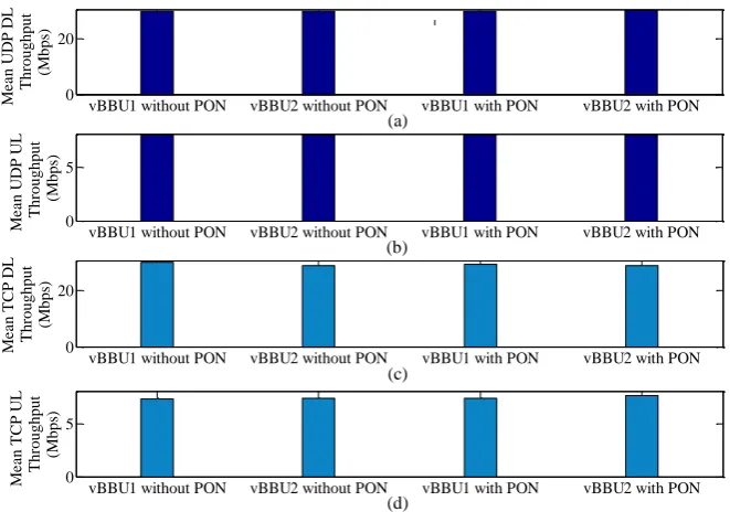
Figure 14 shows that even without existing a TDM-PON on the FH, CRAN can handle multiple traffic from vBBU1 and vBBU2 almost evenly for both TCP and UDP in UL and DL such that the mean throughputs of both TCP and UDP in UL and DL are not affected. This can be underpinned by the fact that with intra-MAC split also called split 5, the resources scheduler is located in the high-intra-MAC in the CU, which can perform centralized scheduling as fairly as possible whether or not they get encountered by a TDM-PON system in the FH. Hence, split 5 is more robust to an increase in load and is not or less susceptible to the presence of TDM-PON in the FH. Also, for systems with multiple UE traffic and reliable data transmission, split 5 is cost-efficient because of avoiding an additional cost from buying a TDM-PON system.
Fig. 14. Mean throughput of UDP and TCP when both vBBUs operate simultaneously with or without inserting a TDM-PON system on FH.
6.3.3. Impact of external delay on the FH
To evaluate the delay performance, we consider varying delay from 0.1 ms to 1.5 ms at max. This is because the FH round trip time with split 5 is set to 2 ms such that any delay inserted on the FH that is higher than 2 ms causes the system to get interrupted. Irrespective of whether or not the real BBU is virtualized (Fig. 15(a)) and the number of vBBUs run in parallel (Fig. 15(b)) in a physical machine, TCP and UDP throughputs
10 20 30 40 50 60 70 80 90 100
27 28 29 30 Time (s) T h ro u g h p u t (Mb p s)
BBU with UDP vBBU1 with UDP vBBU2 with UDP BBU with TCP vBBU1 with TCP vBBU2 with TCP
10 20 30 40 50 60 70 80 90 100
27 28 29 30 Time (s) T h ro u g h p u t (Mb p s)
BBU with UDP vBBU1 with UDP vBBU2 with UDP BBU with TCP vBBU1 with TCP vBBU2 with TCP
(a) (b)
vBBU1 without PON vBBU2 without PON vBBU1 with PON vBBU2 with PON
0 20 M e a n U D P D L T hrough put (M bps )
vBBU1 without PON vBBU2 without PON vBBU1 with PON vBBU2 with PON
0 20 M e a n T CP D L T hrough put (M bps )
vBBU1 without PON vBBU2 without PON vBBU1 with PON vBBU2 with PON
0 5 M e a n U D P U L T hrough put (M bps )
vBBU1 without PON vBBU2 without PON vBBU1 with PON vBBU2 with PON
[image:18.595.136.467.407.639.2]do not deviate considerably from the respective default maximum transmit bandwidths of 30 Mbps in DL and 8 Mbps in UL.
Fig. 15. Impact of FH delay variation with split 5; (a) when only a vBBU and a real BBU operate; (b) when both vBBUs operate simultaneously, and the network delay emulator is common to both vBBUs [17].
6.4. Performance Comparison between Split Options 2 and 5
Recall that, TCP and UDP use different transmit bandwidths in both UL and DL with split 2 and split 5, which are 30 Mbps with split 5 and 70 Mbps with split 2 in DL, whereas 8 Mbps with split 5 and 20 Mbps with split 2 in UL. This reason has been already clarified before. So, because of linear response in received throughputs of TCP and UDP up to the maximum transmit bandwidths with both split 2 (Fig.14) and split 5 in UL and DL, we normalize the throughput responses of both TCP and UDP by their default maximum values for the performance comparison between split 2 and split 5. The values in the following Figs. 16 and 17 are given in percentage of their respective maximum transmit bandwidths.
From Figs. 16(a)-16(b), it can be found that, overall, split 5 provides better DL throughput performances for both TCP and UDP than split 2 irrespective of virtualization of real BBU. Notably, split 5 provides higher mean TCP DL throughputs than split 2 of about 10% and 30% - 40% respectively for the real BBU and vBBUs. However, unlike TCP DL, the outperformance of UDP DL throughputs with split 5 over split 2 is not significant enough. Further, as compared to split 2, the TCP UL throughput with split 5 is improved by about 40% - 45% for vBBUs and more than 50% for the real BBU as shown in Figs. 16(c)-16(d). However, like UDP DL throughputs with split 2, UDP UL throughputs with split 5 do not deviate considerably from that with split 2, irrespective of whether or not the real BBU is virtualized. This is because TCP throughput increases with a decrease in latency due to its congestion control mechanism. Since split 5 requires lower FH latency than split 2 [1], the acknowledgment of received TCP data can be sent faster from the receiver to the sender. This results in faster transmission of new TCP packets and hence improving TCP throughput with split 5 in comparison with split 2.
0.2 0.4 0.6 0.8 1 1.2 1.4 1.5
5 10 15 20 25 30
Delay (ms)
T
h
ro
u
g
h
p
u
t
(M
b
p
s
)
BBU (UDP DL) vBBU (UDP DL) BBU (TCP DL) vBBU (TCP DL) BBU (UDP UL) vBBU (UDP UL) BBU (TCP UL) vBBU (TCP UL)
0.2 0.4 0.6 0.8 1 1.2 1.4 1.5
5 10 15 20 25 30
Delay (ms)
T
h
ro
u
g
h
p
u
t
(M
b
p
s
)
vBBU1 (UDP DL) vBBU1 (TCP DL) vBBU2 (UDP DL) vBBU2 (TCP DL) vBBU1 (UDP UL) vBBU1 (TCP UL) vBBU2 (UDP UL) vBBU2 (TCP UL)
Fig. 16. Impact of virtualization on (normalized) UL and DL throughputs for real BBU and vBBUs running simultaneously with splits 2 and 5 [17].
When considering a TDM-PON system in the FH, it is found that unlike split 2, the mean throughput responses of both TCP and UDP in UL and DL with split 5 are not affected. Hence, split 5 is more robust than split 2 to an increase in load and is not or less susceptible to the presence of TDM-PON in the FH. This can be clarified further by the fact that split 5, even without a TDM-PON system in the FH, can handle multiple traffic better than split 2 with a TDM-PON system considered in the FH for both TCP and UDP in UL and DL as shown in Fig. 17. Such throughput improvement is significant for TCP as compared to UDP traffic. More specifically, the TCP throughput improvement with split 5 is about 30% in DL and 40% in UL as compared to that with split 2. Hence, systems with multiple UE traffic and reliable data transmission, split 5 is more cost-efficient than split 2 since split 2 incurs an extra cost from buying a TDM-PON system. When evaluating the delay performance, as mentioned already unlike split 2, the FH round trip time with split 5 is set to 2 ms so that the system is interrupted when the FH delay exceeds 2 ms. However, within this upper limit of FH delay with split 5, the throughput is unaffected for both TCP and UDP traffic. On the contrary, the throughput with split 2 shows negative exponential decay response with FH delay variation up to 200 ms. Hence, unlike split 2, split 5 shows more robust throughput performance within FH delay varying up to its upper limit.
Finally, to evaluate the impact of packet loss, a delay emulator is inserted between terminals a and b in Fig. 4, while only vBBU1 is made active. From Fig. 18(c), it can be found that UL throughputs of both TCP and UDP traffic are almost unaffected with an increase in packet loss of up to about 5% when operating with both split 2 and split 5. Like UL throughputs, with split 5, DL throughputs of both TCP and UDP traffic remain almost unaffected as well with an increase in packet loss of up to 3% (Fig. 18(d)). However, with split 2, DL throughputs of both TCP and UDP remain almost unaffected up to around 1.5% to 2% packet loss and start decreasing with any further increase in packet loss. It is to be noted that TCP throughputs decrease more steadily than UDP throughput because of its state-full characteristics. Further, when the packet loss is low, i.e. less than 1.5%, dropped TCP packets are retransmitted according to the policy of SCTP. Once the packet loss exceeds about 2%, the lost packets are discarded because of the buffer overflow. Hence, as shown in Fig. 18(d), if packets are discarded, the end-to-end connection of TCP DL traffic cannot be maintained as FH signals also carry control signaling information, e.g. resource scheduling.
10 20 30 40 50 60 70 80 90 100
0.95 0.96 0.97 0.98 0.99 1 Time (s) U D P D L T hr oughp ut ( M bps )
BBU (Split 2) vBBU1 (Split 2) vBBU2 (Split 2) BBU (Split 5) vBBU1 (Split 5) vBBU2 (Split 5)
10 20 30 40 50 60 70 80 90 100
0.2 0.4 0.6 0.8 1 Time (s) T C P D L T hr oughp ut ( M bps )
BBU (Split 2) vBBU1 (Split 2) vBBU2 (Split 2) BBU (Split 5) vBBU1 (Split 5) vBBU2 (Split 5)
20 40 60 80 100
0.94 0.95 0.96 0.97 0.98 0.99 1 1.01 1.02 1.03 Time (s) U D P U L T hr oughp ut ( M bps )
BBU (Split 2) vBBU1 (Split 2) vBBU2 (Split 2) BBU (Split 5) vBBU1 (Split 5) vBBU2 (Split 5)
20 40 60 80 100
0.2 0.4 0.6 0.8 1 Time (s) T C P U L T hr oughp ut ( M bps )
BBU (Split 2) vBBU1 (Split 2) vBBU2 (Split 2) BBU (Split 5) vBBU1 (Split 5) vBBU2 (Split 5) (a)
(c)
(b)
Fig. 17. Normalized mean throughputs of UDP and TCP with split 2 when a TDM-PON system is present, and with split 5 without considering any TDM-PON systems in FH, given that both vBBUs operate simultaneously [17].
Fig. 18. Throughput vs. packet loss: (c) with split 2 and (d) with split 5 [17].
vBBU1 with PON (Split 2) vBBU2 with PON (Split 2) vBBU1 without PON (Split 5) vBBU2 without PON (Split 5) 0.97 0.98 0.99 1 N o rm a li z e d M e a n U D P D L T h ro u g h p u t (M b p s)
vBBU1 with PON (Split 2) vBBU2 with PON (Split 2) vBBU1 without PON (Split 5) vBBU2 without PON (Split 5) 0.6 0.7 0.8 0.9 1 N o rm a li z e d M e a n T C P D L T h ro u g h p u t (M b p s)
vBBU1 with PON (Split 2) vBBU2 with PON (Split 2) vBBU1 without PON (Split 5) vBBU2 without PON (Split 5) 0.96 0.98 1 N o rm a li z e d M e a n U D P U L T h ro u g h p u t (M b p s)
vBBU1 with PON (Split 2) vBBU2 with PON (Split 2) vBBU1 without PON (Split 5) vBBU2 without PON (Split 5) 0.4 0.6 0.8 1 N o rm a li z e d M e a n T C P U L T h ro u g h p u t (M b p s) (c) (d) (b) (a)
0 1 2 3 4
0 10 20 30 40 50 60 70
Packet Loss (%)
T h ro u g h p u t w it h S p li t 2 ( M b p s ) UDP (DL) UDP (UL) TCP (DL) TCP (UL)
0 1 2 3 4
0 5 10 15 20 25 30
Packet Loss (%)
[image:21.595.102.497.571.736.2]7.
Major Limitation and Further Research Scope of PoC Evaluation of vCRAN
In this section, we point out a number of major limitations and further research scopes regarding the PoC evaluation of the proposed vCRAN.
7.1. Effect of Multiple UEs per RRH and Non-ideal FHs
In this paper, we consider one UE per RRH. However, in practice, an RRH typically serves multiple UEs simultaneously. Moreover, we use ideal FHs, i.e. optical fibers, as transport media. However, in reality, there are situations where non-ideal FHs, e.g. millimeter wave, need to be deployed to address constraints such as implementation cost and environmental profile. Since a non-ideal FH has different requirements in terms of, e.g. bandwidth, latency, and jitter, from that of an ideal one, it is worthy enough to understand the impact of non-ideal FHs on CRAN with both split 2 and split 5. We consider these above issues as our further investigation.
7.2. Dynamic Change in Functional Split Options and Placement of CU
This paper assumes static slicing and placement of CU in CRAN. However, in practice, UEs generate a diverse set of services, which vary over time dynamically. Hence, to address such real-time service demands with various performance requirements, a dynamic change in functional split options and placement of the CU is needed. This can be addressed by placing the CU physically at different locations such as local office and central office, though logically they all act as a single entity. Note that this kind of physical decentralization requires tight coordination among CUs at different locations. In addition, to identify a diverse set of service requirements, an auto-detection mechanism needs to be in place at the DUs so that multiple UE services to be served simultaneously by the CRAN can be forwarded to appropriate CUs based on their requirements. We consider such dynamic change in split options and placement of CU as future research studies.
7.3. Coexistence of ARoF and DRoF for the FHs in Post 5G
Though ARoF is envisioned to provide > 100 Gbps per user, in practice so far, about 60 Gbps per user has been reported in literature because of its constraints such as non-linear intermodulation dispersion, chromatic dispersion, no statistical multiplexing gain because of transporting centrally processed data at a constant rate, and high cost of implementation. These require further research works on ARoF to overcome these constraints to achieve a per-user data rate of >100 Gbps in post 5G. In this paper, we limit the scope of evaluation to DRoF in 5G phases. Hence, the application of ARoF for post 5G to provide ultra-high data rate per user is yet to be investigated and considered in the near future. It is to be noted that, using different compression techniques or employing functional split options to fronthaul data, the bandwidth requirement of DRoF can be minimized. Hence, both ARoF and DRoF may coexist to address different requirements in post 5G mobile networks and is considered as further studies.
7.4. Adaptive RAN Slicing
![Fig. 3. Network architectural migration from the current 4G to the prospective 5G and beyond mobile networks [16]](https://thumb-us.123doks.com/thumbv2/123dok_us/8106468.235248/10.595.71.527.204.451/fig-network-architectural-migration-current-prospective-mobile-networks.webp)
![Fig. 4. A prototype of the software architecture of the proposed MCORD based vCRAN [17]](https://thumb-us.123doks.com/thumbv2/123dok_us/8106468.235248/11.595.67.528.414.651/fig-prototype-software-architecture-proposed-mcord-based-vcran.webp)

![Fig. 7. Impacts of change in transmit bandwidth on DL and UL throughputs of UDP without considering TDM-PON systems and delay with split 2 [17]](https://thumb-us.123doks.com/thumbv2/123dok_us/8106468.235248/14.595.88.511.425.666/impacts-change-transmit-bandwidth-throughputs-considering-systems-delay.webp)
![Fig. 9. Impact of virtualization; (a) when vBBU1 or vBBU 2 operates; (b) when both vBBUs operate [17]](https://thumb-us.123doks.com/thumbv2/123dok_us/8106468.235248/16.595.143.458.291.638/fig-impact-virtualization-vbbu-vbbu-operates-vbbus-operate.webp)
![Fig. 11. Impact of change in external FH delay on TCP and UDP throughputs for real BBU and a vBBU without any TDM-PON systems with split 2 [17]](https://thumb-us.123doks.com/thumbv2/123dok_us/8106468.235248/17.595.121.476.472.729/impact-change-external-delay-throughputs-vbbu-systems-split.webp)