Programming Complex Behavior in
DNA-based Molecular Circuits and Robots
Thesis by
Anupama J. Thubagere
In Partial Fulfillment of the Requirements for the Degree of
Doctor of Philosophy, Bioengineering
CALIFORNIA INSTITUTE OF TECHNOLOGY
Pasadena, California
2017
©2017
ACKNOWLEDGEMENTS
My journey through graduate school has seen some unconventional obstacles. My
post graduate education began at Boston University with Franco Cerrina. He not
only nurtured my growth in scientific research but also a love for the arts. He was
a great scientist with an entrepreneurial spirit. His untimely death is an unfortunate
loss for the scientific community and a greater personal loss for people who knew him. I will forever be grateful to have had the privilege to experience his intellect,
leadership and warmth.
I moved to Caltech under the shadow of his loss, and found a welcoming
commu-nity. I started working with Richard Murray and Paul Rothemund who were both
excellent mentors. Richard has always helped me see the big picture, and not lose
sight of the real purpose of my research. Paul helped me understand the precise
details of my work, nothing was ever too small or trivial to discuss.
I am also thankful to everyone in the Murray lab for all the support I have
re-ceived over the years. I feel lucky to have built special and lasting friendships at
Caltech with Marcella Gomez, Victoria Hsiao, Fiona Chandra, Ophelia Venturelli,
Eliza Franco, Melissa Tanner, Yong Wu, Zach Sun, Anandh Swaminathan and Vipul
Singhal. Each in their own way have helped me be the person I am today.
I started working with Lulu Qian in my third year at Caltech. During this time,
I also got more involved with the larger DNA nanotechnology community in Erik Winfree’s lab. The DNA community at Caltech including Chris Thachuck, Robert
Johnson, Damien Woods, Wei Li and Jongmin Kim have helped me with everything
ranging from scientific discussions to feedback on experiments and data analysis to
constructive criticism during rehearsal conference presentations. Lulu in particular
has been an amazing mentor, challenging me to be my best self.
At about the same time that I started working with Lulu, I was diagnosed with
a form of myeloid leukemia. My mentors, friends and family have all been an
amazing source of comfort through the challenges I faced with my health. My husband, Ashwin Gopinath, has been encouraging and loving through the whole
endeavor, helping me stay hopeful. My medical team, headed by Dr. David Snyder
at City of Hope has been incredible in my treatment strategy, indulging my curiosity
in experimental procedures in a safe and fruitful manner. I thank him for everything
Finally, after a few hiccups but with Lulu Qian’s excellent guidance, I have come
to the end of my journey through graduate school having reached milestones I can
ABSTRACT
Integrated electronic circuits, like those found in cellphones and computers, are
ubiquitous in our information-driven society. The success of electronics has, in
part, been due its modular architecture that enables individual components to be
independently improved while the overall device functionality remains unchanged.
Over the last two decades the emerging field of dynamic DNA nanotechnology has been trying to apply the underlying philosophy of electronics to biochemical
cir-cuits. DNA nanotechnology employs rationally designed DNA molecules as
build-ing blocks of biochemical circuits that can, in principle, enable powerful
applica-tions like diagnostics and therapeutics.
Researchers in the field of DNA nanotechnology have developed simple elements to
construct biomolecular systems with desired functions. They have also developed
molecular compilers for defining design principles. The cost of DNA synthesis has
decreased by over three orders of magnitude in the past decade. This has lead to a non-trivial number of small scale circuits, like DNA-based logic gates and chemical
oscillators, being implemented. However, the scalability of this approach has yet to
be clearly demonstrated.
In this thesis, we will discuss our main contributions to facilitating the
advance-ment of DNA nanotechnology by developing systematic approaches for
construct-ing modular DNA buildconstruct-ing blocks. These modules can be used to construct
bio-chemical circuits and molecular robotic systems. The performance of the modules can be individually tuned and integrated into large-scale systems.
Using automated circuit-design software and cheap unpurified DNA, we
demon-strated the design and construction of a complex synthetic biochemical circuit
con-sisting of 78 distinct DNA species. The circuit is capable of computing the
transi-tion rules of a cell updating its state based on its neighboring cells, defined in a
clas-sic computational model called cellular automata. Using a bottom-up approach, we
first characterized the component necessary for basic Boolean logic computation.
We then systematically integrated more circuit elements and eventually constructed the full circuit. By developing a systematic procedure for building DNA-based
circuits using unpurified components, we significantly simplified the experimental
procedure. By using unpurified DNA components, we reduced the cost and
DNA circuits accessible to even novice researchers.
Next we demonstrated a cargo sorting DNA nano-robot, using a simple algorithm
and modular building blocks. The DNA robot has a leg and two foot domains for
exploring a two-dimensional DNA origami surface, and an arm and hand domain
for picking up randomly located cargos and dropping them off at their designated
locations. It is completely autonomous and is programmed to perform a random
walk without requiring an external energy source. Further, we demonstrated sorting
multiple copies of two distinct cargo species on the same origami. Additionally,
by compartmentalizing each sorting task on a single origami, we showed that two
distinct sorting tasks can be implemented on different origami simultaneously in the
same test tube. The recognition of a cargo is embedded in its destination, therefore it is possible to scale up the system simply by having multiple types of cargos. The
same robot design can be used for performing multiple instances of distinct tasks
in parallel. The different modules can be integrated to perform diverse functions,
PUBLISHED CONTENT AND CONTRIBUTIONS
[1] Anupama J Thubagere et al. “Compiler-aided systematic construction of large-scale DNA strand displacement circuits using unpurified components”. In: Nature Communications8 (2017).
A.J.T. designed and performed the experiments and analysed the data of the full circuit and led the project to completion. A.J.T and L.Q wrote the manuscript.
[2] Anupama J Thubagere et al. “A cargo-sorting DNA robot”. In: Submitted (2017).
TABLE OF CONTENTS
Acknowledgements . . . iii
Abstract . . . v
Published Content and Contributions . . . vii
Table of Contents . . . viii
Chapter I: Introduction . . . 1
1.1 Overview of DNA nanotechnology . . . 3
1.2 DNA as a computing substrate . . . 5
1.3 DNA as an engineering material . . . 8
Chapter II: Systematic construction of DNA circuits . . . 11
2.1 Circuit design . . . 14
2.2 Calibrating effective concentrations. . . 20
2.3 Identifying outliers. . . 25
2.4 Tuning circuit output. . . 27
2.5 Systematic procedure . . . 29
2.6 Model . . . 32
2.7 Methods . . . 38
Appendix . . . 40
2.A Additional design diagrams . . . 40
2.B Additional experimental data . . . 42
2.C Additional modeling details . . . 44
2.D DNA sequences . . . 49
Chapter III: A random walk module for DNA robots. . . 53
3.1 Implementing random walking DNA robot on DNA origami . . . 54
3.3 Rigidity of DNA origami as a testing ground for DNA robots . . . . 60
3.4 DNA sequence and its effect on the rate of walking . . . 62
3.5 Purity of DNA origami and its effect on the reaction completion level 67 3.6 Demonstration of the random walk . . . 73
3.7 Model . . . 75
Chapter IV: A cargo-sorting DNA robot . . . 79
4.1 A simple cargo-sorting algorithm . . . 80
4.2 Molecular implementation of the algorithm . . . 81
4.3 Demonstration of the robot picking up cargos . . . 84
4.4 Inhibition and activation mechanism of cargo destinations . . . 88
4.5 Negative control for cargo-sorting without a robot . . . 93
4.6 Demonstration of the robot sorting cargos . . . 94
4.7 Demonstration of distinct cargo-sorting tasks in parallel . . . 97
4.8 Model . . . 102
4.9 Methods . . . 108
Appendix . . . 110
4.A Additional design diagrams . . . 110
4.B Additional experimental results . . . 111
4.C DNA sequences . . . 112
Chapter V: Conclusions . . . 121
C h a p t e r 1
INTRODUCTION
The origins and propagation of life has fascinated scientists for generations.
Pri-mordial life is believed to have originated with chemical molecules (nucleic acids,
amino acids) reacting with each other in compartments. Over time the
compart-ments developed into more sophisticated biological cells representing life.
Scien-tists over time have worked to understand the complexities surrounding a single
cell, its metabolism, its ability to respond to external stimuli and its replication
properties using various scientific tools including different engineering approaches. Gregor Mendel in 1865 proposed the law of biological inheritance, suggesting the
idea that biological life follow certain rules and copies of these rules get passed on
to future generations. This inspired a new field of thought encouraging researchers
to find evidence to aid in deciphering these rules.
Erwin Schrödinger’s "What is life?" lecture [1] explains a theoretical physicists view on the physical aspect of the living cell. In his lectures, Schrödinger
intro-duced the idea of an "aperiodic crystal" that contained genetic information in its
configuration of covalent chemical bonds. Jon von Neumann inspired a new gener-ation of scientists by introducing growth and reproduction as informgener-ation
process-ing tasks [2]. Alan Turing, with his work on chemical morphogenesis [3] provided insights into computations involved in biological growth.
Before Schrödinger, for over 50 years since its discovery, deoxyribonucleic acid
(DNA) had been thought of primarily as a biological molecule. First isolated in
1869 by a Swiss physician Friedrich Miescher when he noticed a microscopic
sub-stance in discarded surgical bandages, DNA was mostly known to be a cell
compo-nent that had important function as it was located in the nucleus. By early 1900s, it was also known that DNA consisted of two types of molecules: purines and
pyrimidines. By 1952, Chargaff had discovered that all organisms have 1:1 ratio
of purine and pyrimidine bases in their DNA and that different organisms had
dif-ferent amounts of these molecules [4]. Chargaff’s rules helped James Watson and Francis Crick to solve the crystal structure of DNA in 1953 [5]. The double helical structure of DNA itself was crystallized by Rosalind Franklin and Maurice Wilkins.
molecule at the atomic level( fig.1.1). What came next were the constituent alpha-bets composing the DNA molecule. DNA is made of four chemical bases:
adeno-sine (A), thymidine (T), guanadine (G) and cytoadeno-sine (C).
There exist atleast three different conformation of DNA: A-DNA, B-DNA and
Z-DNA. The B form described by James Watson and Francis Crick is believed to
predominate in biological cells [6]. Each of the bases in the B-form string along a sugar-phosphate backbone separated by a distance of 0.43 nm. A binds to T via
double hydrogen bonds and G binds to C via triple hydrogen bonds. A single strand
of DNA binds to its complementary strand following this rule. The double helical
structure is about 2 nm wide and the distance between base pairs reduces to 0.34
nm. The double helix is stabilized by the stacking interaction between the bases. Further, the double helix exhibits a left-handed turn approximately every 10.5 base
pairs (bp), i.e, ~3.6 nm.
1
tu
rn
=
~
1
0
ba
se
s
=
~
3.
4
nm
Figure 1.1: Diagram of DNA structure. The two ribbons symbolize the two phosphate-sugar chains and the horizontal rods symbolize the bases holding the chain together. The
vertical lines mark the DNA fiber axis. Reproduced from [5].
In the last two decades, the emergent field of DNA nanotechnology has featured
DNA molecules for designing a large library of molecular systems capable of per-forming complex information processing functions using networks of bimolecular
components [7,8]. The information of the physical structure of DNA gathered by Watson and Crick has been crucial to the molecular programming community in
redefining DNA as an engineering material and a computing substrate
implement-ing various structural properties and dynamic behaviors in DNA-based devices. In
general, the understanding of the structural, thermodynamic and kinetic properties
of DNA has aided the development of DNA nanotechnology. Furthermore,
produc-tivity of DNA synthesis has increased by nearly five orders of magnitude over the
Along with DNA synthesis, technological advancements towards visualization and
manipulation of matter at the nanoscale level have been of significance. Super
resolution microscopy techniques such as DNA PAINT [10] and high-speed atomic force microscopy has enabled characterization of objects at the nanoscale and in
[image:12.612.208.401.171.341.2]some cases visualization of dynamic molecular events [11].
Figure 1.2: Changing economics of DNA synthesis. Since 1990, cost of oligo
synthe-sis per base has dropped about two orders of magnitude while synthesynthe-sis productivity has
increased by five orders of magnitude. Reproduced from [9].
Advancements in oligo synthesis and visualization techniques at the nanoscale have
contributed to the growth of DNA nanotechnology by helping researchers design
various experimental and computational tools. Amongst these, a number of
com-pilers that help design DNA for building sophisticated DNA-based devices have
been developed [12–14]. Furthermore, the development of structural components at the nanoscale using DNA has contributed towards the development of localized
computation schemes [15]. In this thesis, we will discuss our main contributions toward facilitating the advancement of DNA nanotechnology by developing sys-tematic approaches for constructing modular DNA building blocks. These modules
can be used to construct biochemical circuits and molecular robotic systems. The
performance of the modules can be individually tuned and integrated into large
scale systems.
1.1 Overview of DNA nanotechnology
DNA has well understood mechanical [16] and thermodynamic [17,18] properties. The stability of a DNA double helix can be predicted from the contributions of each
fast algorithms can be designed to predict folding from DNA sequence and also
permit sequence design given a prescribed structure.
Inspired by the replication junction and the Holliday structure, a critical
interme-diate in genetic recombination, Ned Seeman in 1982 theorized the ability to study
such biologically relevant reactions using strand displacement mechanisms [19] that could easily be mimicked using synthetic DNA molecules. He also envisioned
cre-ating three dimensional lattices from such three and four-armed junctions. The goal
was to use these DNA lattices as scaffolds for facilitating the crystallographic study
of protein structure. While this turned out to be more challenging to implement, it
gave rise to the idea of self-assembled structures using synthetic DNA and led to
the development of structural DNA nanotechnology. The initial idea for forming small tiles and simple structures along with the development of efficient software
tools has given way to designing versatile DNAorigamistructures in two and
three-dimensions.
Len Adleman had the pioneering thought of using DNA molecules to perform
com-putations [20]. The parallelism provided by DNA molecules mixed in a test tube was used to solve a seven-node Hamiltonian path problem. While scaling up such
reactions proved impractical, the work itself inspired several others to build DNA-based systems that could be programmed to perform interesting and complex
com-putation tasks, thus paving way to building dynamic systems. Of particular
con-sequence was Bernie Yurke’s work on molecular tweezers using DNA strand
dis-placement mechanism [21]. Strand displacement mechanism was first observed in a viral DNA replication where an invader strand uses the single-stranded overhang on
a double-stranded DNA plasmid. Using the overhang, the invader strand manages to
displace the bound strand and taking its place. DynamicDNA nanotechnology has
been used widely to implement all-DNA systems which can execute enzyme-free
logic [22], implement cellular automaton rules [23], act as a catalyst [24], compute square root of a number [25], exhibit oscillations [26], and also used as a pro-grammable module for dynamic self-assembly [27]. Specifically, the mechanism of toehold mediated strand displacement [21,28–30] has been used extensively for implementing the above mentioned systems and continues to be extremely relevant
1.2 DNA as a computing substrate
Much like the way in which complex electrical circuits are built with simple
primi-tives, molecular programming uses DNA strand displacement components to build
computational systems which can implement catalytic reactions and feed-forward
Boolean logic circuits. An active and growing community of molecular
program-mers have contributed to the development and widespread use of designed
automa-tion. For example, Visual DSD [31,32] is a custom programming language which is commonly used for verifying, simulating and analyzing strand displacement cir-cuits by enumerating and simulating the corresponding strand displacement
reac-tions. Another great example is Nupack [12] which has gained popularity given its ease of use for analyzing and designing nucleic acid systems. The Nupack
com-piler provides an environment for testing nucleic acid sequences for structure
ver-ification at thermodynamic equilibrium. Such software tools provide great insight
into implementing dynamical behaviors using DNA. Furthermore, the molecular
architecture of DNA provides an elegant way of varying rate constants by orders
of magnitude by simply tuning the length of the sub-sequence of the reactant DNA
molecule called the "toehold". The following figure illustrates the strand displace-ment mechanism at the sub-sequence level, which will henceforth be referred to as
the "domain" level.
A domain consists of a continuous string of nucleotides that are either fully bound
or unbound in their stable configuration (fig.1.3a). Figure1.3 is reproduced from [7]. The system used in this study describes the interaction between a two-stranded DNA complex (X) and a single-stranded invader (A). The single-stranded DNA
strand A reacts with double-stranded DNA complex X to release strand B and com-plex Y. Strands that initiate the reaction are called inputs (A) and strands released
from the complexes are referred to as outputs (B). The strand-displacement reaction
is facilitated by the toehold domains 3 and 3∗ : the hybridization of these single-stranded toeholds co-localizes A and X, and allows domain 2 to branch migrate.
Branch migration is an unbiased random walk process [29, 33] in which one do-main displaces another of identical sequence through a series of reversible single
nucleotide dissociation and hybridization steps. At the completion of branch
mi-gration, complex Y is formed and strand B is released. Overall, displacement is
thermodynamically driven forward by the net gain in base pairs due to the toehold.
The progress of strand-displacement reactions is typically assayed using fluores-cence, mostly by means of fluorophore quencher reporter complexes that produce
Figure 1.3: Overview of DNA strand displacement. a,Abstraction of contiguous DNA bases into functional DNA domains that act as a unit in hybridization, branch migration
or dissociation represented by numbers, starred domains denote domains complimentary in
sequence to domains without a star. b, An example of DNA strand displacement
mecha-nism indicating initiation by toehold binding, continuing to branch migration and ending
in disassociation of output strand completing the reaction. c,Kinetics of strand
displace-ment modeled and predicted from length and sequence of toehold domain. This figure is
reproduced from [7].
The overall effective rate of the strand displacement reaction keff was first studied by Yurke and Mills [28]. They observed an exponential acceleration in keff with toehold length. Zhang and Winfree [29] further explored the exponential accelera-tion of reacaccelera-tion rate with toehold strength and confirmed its saturaaccelera-tion in the long
toehold limit. They summarized the rate constant of the strand displacement
reac-tion varies over a factor of 106, from 1M−1s−1to 6×10⁶ M−1s−1(fig.1.3c). They verified the kinetics for different toehold strengths confirming that DNA devices
based on strand displacement will work for most choices of domain sequences.
They tested kinetics with multiple toeholds consisting only G/C nucleotides (green
trace), A/T nucleotides (red trace) and finally toeholds that had roughly equal
num-ber of all four nucleotides (black trace). The gray region spanned by the green and red traces roughly shows the range of potential kinetics based on toehold length.
The data from both studies suggest that the keff is an effect of sequence design and variation of toehold sequence and experimental conditions may affect reaction
rate. A special case of strand displacement initiation can occur without free
strand displacement and found it to be ~1M−1s−1at 25 °C in agreement with previ-ous studies [34]. The zero-toehold reactions may cause undesired interactions and need to be considered while designing a strand displacement system. Such detailed biophysical studies of strand displacement systems along with the development of
supporting design and analysis software has been the cornerstone of the
achieve-ment by the dynamic DNA nanotechnology community.
While DNA strand displacement has been leveraged to implement feedforward
Boolean logic circuits [22], scaling up DNA-based digital circuit computation is a daunting challenge and a remarkable step was taken by Qian et al. [25] to build a DNA strand displacement circuit composed of 82 single- and partially
double-stranded DNA circuit components in a single test tube representing a four-bit square-root calculating digital logic circuit. The circuit composed of multiple layers of
cascading AND-OR seesaw logic gates [35]. Each logic gate had an inbuilt digital signal restoration mechanism that included thresholding and catalysis to assist in
tuning circuit behavior. Thus far, another circuit of this size and complexity has
not been attempted. The study also introduced a molecular compiler which can in
theory, be used to design any arbitrary feedforward DNA-based digital logic circuit
using seesaw logic gates. The compiler also provides necessary simulation tools to
predict circuit behavior.
Designing and building large-scale DNA circuits is both laborious and time
con-suming. The square-root circuit has 82 DNA circuit components, in total 130 DNA
strands, forming bimolecular complexes. To maintain the desired stoichiometry of
molecules and reduce spurious/ undesired reactions, the DNA complexes have to
be annealed and purified in-house which requires both time and skilled labor. The
compiler that was developed in parallel with the circuit construction has not been
independently validated to date.
Chapter 2 of this thesis seeks to independently validate the seesaw compiler by
us-ing it to design and implement a large 78-component logic circuit. We define a
framework under which a circuit of this size can be tested in a matter of 3-6 days
and cuts out the need for intensive purification techniques, making it more user
friendly. We believe such a simplistic methodology which has already proved
ex-tremely successful in a classroom setting will redefine building complex molecular
1.3 DNA as an engineering material
One restriction with building arbitrarily large DNA systems using toehold
medi-ated strand displacement is the toehold sequence. While using orthogonal toeholds
minimize cross talk between various reactant species, there are only a finite
num-ber of orthogonal toeholds available at any relevant toehold length. As the system
gets larger, a way around is to use universal toeholds as designed in the seesaw
system. Universal toeholds are common sequence toeholds wherein strand
dis-placement reactions for all species in the reaction mixture can be initiated in using a single toehold. Since the strand displacement system is implemented in a
well-mixed solution, the number of pair-wise interactions possible in the test tube scales
quadratically with the size of the DNA implementation. This has the potential to
exacerbate cross-talk between species in the test tube and perhaps puts a ceiling on
the size of the circuit. Such a problem could be mitigated by lowering the
concen-tration of the species, however, this would also scale down the concenconcen-tration range
of the intended dynamical behavior. In addition, the intended dynamical behavior
would occur at much lower rates and would increase the observation time leading
to other experimental challenges.
Implementing DNA circuits tethered to a surface could be a possible solution [15, 36,37] since limiting interactions to species that are co-localized can reduce spuri-ous interactions and allow domains to be re-used multiple times. DNA origami [38] provides one such surface where biomolecules can be tethered using DNA
hy-bridization to localize molecules at distinct locations at the nanoscale.
Paul Rothemund in 2006 introduced the DNA origami technique for the self-assembly of DNA nanostructures with high fidelity. He employed a viral (M13) DNA strand
with an established sequence as a scaffold, folding it into the target shape using
smaller synthetic DNA strands (staples) with Watson-Crick complementarity to the
scaffold strand (fig.1.4). The staple DNA strand can be extended on either the 5’ or the 3’ end providing a binding sequence for hybridizing a molecule of interest
to the origami. Each of these extensions can be easily made orthogonal by using
the available DNA sequence design space, providing unique binding sites for
local-izing molecules of interest. An origami design software, caDNAno [39] provides an intuitive platform for designing target origami structures and respective staples. The software can be used to design and modify two and three-dimensional
be inserted into an artificial cell membrane to act as active membrane channels [44].
a
b
c
Figure 1.4: Making DNA origami. a,M13 viral scaffold is mixed with designed staple
strands in 1× TAE/12.5 mM Mg++and annealed to form target triangle structure designed in caDNAo.b,Schematic of designed triangle DNA origami. The blue and green dots
rep-resent uniquely addressable 5’ staple extension locations. c,The triangular nanostructures
are visualized using atomic force microscopy.
Harnessing the computational power of the DNA molecule as well as its ability to
form complex structures which can act as scaffolds upon which computation can
take place has led to the development of nanorobots. Information is programmed
into the design of the sequences of the DNA strands making up the robot and
the tracks. Programming robots that are capable of tasks ranging from taking a
few steps in a single direction [45], to making decisions based on environmental cues [46], to picking up and carrying cargo in the form of gold nanoparticles [47] are a few examples which showcase the extent of control possible at the nanoscale. While there are molecular transporters that can operate without needing external
control [48,49], designing more complex robotic systems which can process infor-mation autonomously can be beneficial for implementing complex behaviors.
De-veloping molecular robotic systems capable of responding to external stimuli and
pass control signals would be highly applicable in the field of targeted therapeutics.
Having molecular robots perform complex cooperative tasks could help implement
‘social’ robotics [50] and perhaps even be useful in fabrication of molecular de-vices [51]. Furthermore, these robots provide a unique opportunity to study the biophysics of localized molecules while using minimally invasive techniques for
localization [52–54].
undirectional walking or choosing a particular path or picking up cargo. The
func-tionality of these robots have mostly been their ability to move. The cargo-picking
robot [47] is capable of walking and picking up 3-cargo molecules using its triangu-lar geometry, and is non-autonomous. The robotic system gets quickly complicated
if the number of cargo molecules increase. Also, the robot can only perform a
single iteration of cargo pick-up and scaling up the functions of this robot is a
non-trivial task. Our work (covered in chapters 4, 5) combines the modularity of an
autonomous robot capable of walking and the performance of a programmed task
using simple algorithm.
Chapter 3 of this thesis addresses a systematic approach to identifying and
charac-terizing an important module for a nanorobot capable of performing 1-dimensional random walk on a DNA nanostructure using reversible strand displacement
reac-tions. The robot walks exclusively by using base-pair hybridization and
disasso-ciation, allowing it to be used for continuous exploration of the nanoscale surface
using uniquely positioned tracks, without exhausting any kind of fuel.
Chapter 4 expands the functionality of the designed random-walking robot by
pro-graming it to explore the 2-dimensional surface of the nanostructure. In concert
with the exploration, the robot is programmed to perform the complex task of sort-ing randomly distributed cargo to their designated goal locations on the nanoscale
surface of DNA origami. Our experimental demonstration shows the sorting of two
types of cargo, but in principle, the system can be scaled up to sort a larger number
C h a p t e r 2
SYSTEMATIC CONSTRUCTION OF DNA CIRCUITS
A hallmark of electrical engineering has been the development of simple primitives
aiding the construction of complex electrical circuits. One of the primary aims of
molecular programming is to develop a library of primitives which can be used
to construct complex molecular circuits. To that end, biomolecular DNA
compo-nents have been successfully implemented using toehold mediated strand
displace-ment reactions to device small circuits. The simple bimolecular components are
cascaded to engineer molecular devices with interesting dynamic properties which include nano-scale machines like molecular tweezers [21], catalytic amplifiers [22] and molecular oscillators [26,55].
To further advance the engineering of such complex devices, software tools such
as molecular compilers capable of translating high-level instructions to low-level
molecular interpretation have been developed. A molecular reaction system
com-piled to DNA molecules has three main steps. The first step is where the system
is run through a compiler to break it down into domain specific DNA molecules.
Next, the domains are converted into DNA sequences and nucleotides. And finally, the sequences are sent out to a commercial vendor for synthesis before the reaction
can be implemented in a laboratory setting.
Multiple compilers that convert reaction mechanisms to DNA domains have been
developed. Soloveichik et al., [56] developed a compiler to translate arbitrary chem-ical reactions to real and experimentally implementable reactions. Visual DSD [32] was developed as a design and analysis tool for DNA strand-displacement systems.
The software provides support for enumerating the designed reactions and
simulat-ing them.
The next step to implementing molecular systems is to translate the DNA domains
produced by the compiler into DNA sequences. Some compilers have an inbuilt
function to generate DNA sequences for the corresponding circuit design [25], spe-cial software tools like NUPACK [12] have been developed specifically to design nucleic acid sequences and ascertain the thermodynamic properties of designed
molecules. Several other tools assisting with calculating kinetic properties of
de-sired higher-level functions [32,58,59] have also been developed.
While some of the compilers mentioned above have been developed by
incorporat-ing experimental data [25, 56], none have been independently validated, i.e, these compilers have not been used to design and test additional DNA circuits.
The final stage of circuit construction involves the synthesis of designed DNA
se-quences. Most researchers use commercial vendors for this purpose. Decades of
research has resulted in the synthesis of synthetic oligonucleotides being cheaper,
efficient and easily obtainable [9]. The oligos can be ordered purified or unpurifed. Purification of oligos is performed either by poly acrylamide gel electrophoresis (PAGE) or high pressure liquid chromatography (HPLC) columns, where molecules
with truncated bases are separated from designed molecules. Purification increases
the cost of oligos by 10-fold. Several researchers prefer to perform in-house
purifi-cation using PAGE to separate malformed DNA structures from desired structures.
In-house purifications are time and labor intensive. However, purification of circuit
components reduce undesired products that are caused by stoichiometric errors [25, 60]. While purification has certain advantages, it significantly increases the cost and time required for building large-scale DNA circuits.
This chapter focuses on independent validation of a molecular compiler [14] that was used to generate DNA sequences for implementing a large-scale DNA circuit.
Using a systematic hierarchical method, we show that unpurified strands can be
successfully used to implement DNA circuits.
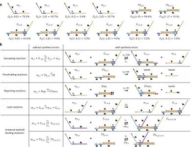
Review of the DNA Seesaw motif
This section is a brief review of the seesaw DNA motif developed by Qian et al to
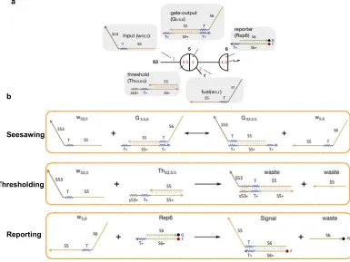
scale up complexity of DNA circuits [35] and demonstrating their ability to imple-ment digital logic computation [25] and neural network computation [61]. In the seesaw abstraction, each DNA gate is represented by a two-sided node (fig.2.1a). Each DNA signal is represented by a wire. Each side of the node can be connected to any number of wires. Each wire connects two different sides of two nodes. Each
red number indicates one DNA species with its initial relative concentration. Each
number on a wire corresponds to a free signal strand; each number within a node
at the end of a wire corresponds to a bound signal strand (positive number) or a
threshold that absorbs a signal when it arrives at the gate (negative number). The
fuel molecule contributes to the catalytic nature of the reaction. A reporter that
with a zigzag arrow, with its initial relative concentration indicated by the number
inside the hemispherical node.
Seesawing
Thresholding
Reporting a
[image:22.612.116.501.137.426.2]b
Figure 2.1: The Seesaw DNA motif. a, Each DNA gate is represented by a two-sided node, connected through wires. b, There are 3 types of reactions: the first is seesawing where the input strand can reversibly displace the top-strand of the gate:output complex. The second is the thresholding reaction that irreversibly binds the input strand. The final is the reporting reaction where the output strand from the seesawing reaction displaces the quencher strand from the fluorophore-quencher reporter complex producing a fluorescent signal.
There are three basic reactions involved in a seesaw network (fig. 2.1b). The first is seesawing: A free signal on one side of a gate can release a signal bound on the
other side of the gate by toehold-mediated strand displacement. The process starts
with the free signal strand (e.g., w53,5) hybridizing to the gate:signal complex (e.g.,
G5:5,6) at the uncovered toehold domain (e.g., T*) and then undergoing branch
mi-gration through the recognition domain (e.g., S5). The previously bound signal will
fall off when it is attached to the gate base strand only by the short toehold. The
resulting gate:signal complex (e.g., G53,5:5) will have an uncovered toehold on the other side, and therefore the now-free signal (e.g., w5,6) can reverse the process
with a gate and an impinging signal can react with the signal by means of a longer
toehold (e.g., s53*T*), producing only inert waste species that have no exposed
toehold. Thresholding is much faster than seesawing because the toehold-mediated strand displacement rate grows exponentially with toehold length for short toeholds
[29]. As a result, seesawing effectively only happens when the input signal exceeds the threshold. The third reaction is reporting: A reporter species similar to a
thresh-old, but modified with a fluorophore and quencher pair, can absorb an impinging
signal while generating a fluorescence signal. Unlike thresholding, reporting does
not compete with seesawing, and it therefore does not require a longer toehold.
Using the seesaw motif, we can build two distinct type of seesaw gates. The first
kind is the amplifying gate which has the threshold and fuel. If input is greater than the threshold, the output is released catalytically. It can support multiple outputs.
The second kind is the integrating gate which has no threshold or fuel and the output
is released as sum of inputs. It can support multiple inputs. An integrating gate
followed by an amplifying gate can compute either OR or AND logic. A two-input
OR gate will have an integrating gate that outputs the sum of the two inputs. The
downstream amplifying gate will output 1 when the sum is greater than 0.6 and will
output 0 otherwise. In practice, the outputs will not be exactly 0 or 1 because of
spurious or incomplete reactions, so we must ensure that logic gates will function
correctly even with imperfect inputs. Assuming a digital abstraction where OFF signals may be in the range 0 to 0.2 and ON signals in the range 0.8 to 1, we see
that only when both inputs are OFF can the output remain OFF. Similarly, changing
the threshold from 0.6 to 1.2 computes AND. In this case, only when both inputs
are ON can the sum exceed the threshold and catalyze the output to be ON.
2.1 Circuit design
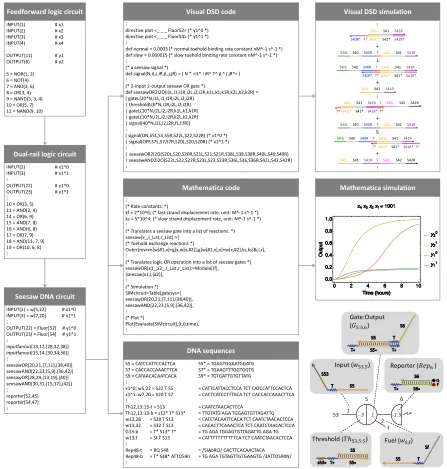
The Seesaw Compiler [14, 25] automatically translates an arbitrary feedforward digital logic circuit into its equivalent seesaw circuit (fig.2.2). Input to the compiler is a logic circuit consisting of AND, OR,NAND,NOR and NOT gates with their
connectivity specified. The compiler then generates an equivalent dual-rail circuit
file consisting of AND-OR gates only [62]. NOT gates are difficult to implement directly using representations where the ON or OFF state of an input is determined
by the presence or absence of a single DNA species: a circuit might compute a
false output before all input strands are added, because NOT gates already produce
ON signals in the absence of their inputs, and for use-once circuits (such as seesaw
input is replaced by a pair of inputs, representing logic ON and OFF separately.
Each logic gate in the designed circuit is replaced by a pair of AND or OR gates.
INPUT(1) # x1
INPUT(2) # x2
INPUT(3) # x3
INPUT(4) # x4
OUTPUT(11) # y1
OUTPUT(8) # y2
5 = NOR(1, 2) 6 = NOT(4) 7 = AND(3, 6) 8 = OR(3, 4) 9 = NAND(5, 3, 4) 10 = OR(5, 7) 11 = NAND(9, 10)
Feedforward logic circuit
INPUT(2) # x1^0
INPUT(3) # x1^1
⋮
OUTPUT(22) # y1^0 OUTPUT(23) # y1^1
⋮
10 = OR(3, 5) 11 = AND(2, 4) 14 = OR(6, 9) 15 = AND(7, 8) 16 = AND(6, 8) 17 = OR(7, 9) 18 = AND(11, 7, 9) 19 = OR(10, 6, 8)
⋮
Dual-rail logic circuit
INPUT(2) = w[5,22] # x1^0 INPUT(3) = w[7,20] # x1^1
⋮
OUTPUT(22) = Fluor[52] # y1^0 OUTPUT(23) = Fluor[54] # y1^1
⋮ inputfanout[13,12,{28,32,38}] inputfanout[15,14,{30,34,36}] ⋮ seesawOR[20,21,{7,11},{38,40}] seesawAND[22,23,{5,9},{36,42}] seesawOR[28,29,{13,19},{40}] seesawAND[30,31,{15,17},{42}] ⋮ reporter[52,45] reporter[54,47] ⋮
Seesaw DNA circuit
⋮
directive plot <_ _ _ Fluor52> (* y1^0 *) directive plot <_ _ _ Fluor54> (* y1^1 *)
⋮
def normal = 0.0003 (* normal toehold binding rate constant nM^-1 s^-1 *) def slow = 0.000015 (* slow toehold binding rate constant nM^-1 s^-1 *)
⋮
(* a seesaw signal *)
def signal(N,iL,i,iR,jL,j,jR) = ( N * <iL^ i iR^ T^ jL^ j jR^> )
⋮
(* 2-input 2-output seesaw OR gate *)
[image:25.612.83.530.75.544.2]def seesawOR2I2O(i1L,i1,i1R,i2L,i2,i2R,k1L,k1,k1R,k2L,k2,k2R) = ( gateL(20*N,i1L,i1,i1R,i2L,i2,i2R) | thresholdL(6*N,i1R,i2L,i2,i2R) | gateL(10*N,i2L,i2,i2R,k1L,k1,k1R) | gateL(10*N,i2L,i2,i2R,k2L,k2,k2R) | signal(40*N,i2L,i2,i2R,fL,f,fR)) ⋮
( signal(ON,S5L,S5,S5R,S22L,S22,S22R) (* x1^0 *) | signal(OFF,S7L,S7,S7R,S20L,S20,S20R) (* x1^1 *)
⋮
| seesawOR2I2O(S20L,S20,S20R,S21L,S21,S21R,S38L,S38,S38R,S40L,S40,S40R) | seesawAND2I2O(S22L,S22,S22R,S23L,S23,S23R,S36L,S36,S36R,S42L,S42,S42R)
⋮
Visual DSD code
⋮
(* Rate constants: *)
kf = 2*10^6; (* fast strand displacement rate, unit: M^-1 s^-1 *) ks = 5*10^4; (* slow strand displacement rate, unit: M^-1 s^-1 *)
⋮
(* Translates a seesaw gate into a list of reactions: *) seesaw[x_,l_List,r_List]:={
(* Toehold exchange reactions *)
Outer[revrxn[w[#1,x]+g[x,w[x,#2]],g[w[#1,x],x]+w[x,#2],ks,ks]&,l,r],
⋮
(* Translates logic OR operation into a list of seesaw gates *) seesawOR[x1_,x2_,l_List,r_List]:=Module[{f}, {seesaw[x1,l,{x2}],
⋮
(* Simulation *) SIMcircuit=Table[gatesys={ seesawOR[20,21,{7,11},{38,40}], seesawAND[22,23,{5,9},{36,42}],
⋮
(* Plot *)
Plot[Evaluate[SIMcircuit],{t,0,time},
⋮
Mathematica code
S5 = CATCCATTCCACTCA S5* = TGAGTGGAATGGATG S7 = CACCACCAAACTTCA S7* = TGAAGTTTGGTGGTG S9 = CATAACACAATCACA S9* = TGTGATTGTGTTATG
⋮
x1^0: w5,22 = S22 T S5 = CATTCATTACCTCCA TCT CATCCATTCCACTCA x1^1: w7,20 = S20 T S7 = CACTCATCCTTTACA TCT CACCACCAAACTTCA
⋮
Th12,13:13-t = S13 = CAATCTAACACTCCA Th12,13:13-b = s12* T* S13* = TTGTATG AGA TGGAGTGTTAGATTG w13,28 = S28 T S13 = CATCTACAATTCACA TCT CAATCTAACACTCCA w13,32 = S32 T S13 = CACACTTCAAACTCA TCT CAATCTAACACTCCA G13-b = T* S13* T* = TG AGA TGGAGTGTTAGATTG AGA TG w13,f = Sf T S13 = CATTTTTTTTTTTCA TCT CAATCTAACACTCCA
⋮
Rep48-t = RQ S48 = /5IAbRQ/ CACTTCACAACTACA Rep48-b = T* S48* ATTO590 = TG AGA TGTAGTTGTGAAGTG /3ATTO590N/
⋮
DNA sequences
Visual DSD simulation
⋮ ⋮ Mathematica simulation + + + + ⋮ 53 f 5 2 -.5 1 6 -1.5 1 Gate:Output (𝐺5:5,6)
Fuel (𝑤5,f) Reporter (𝑅𝑒𝑝6)
Input (𝑤53,5)
Threshold (𝑇ℎ53,5:5)
S41L S41 S41R
S41L* S41* S41R* T*
S40R*
S41L S41 S41R T S40R S40 S40L ↓ ⇌
S41L S41 S41R
S41L S41 S41R T
S40R
S40 S40L
S41L* S41* S41R* T*
S40R*
S41L S41 S41R T S42L S42 S42R
S41L* S41* S41R*
T* T*
S41L S41 S41R T
S40R
S40 S40L
S41L S41 S41R T S42L S42 S42R
S41L* S41* S41R*
T* T*
S41L S41 S41R T
S40R
S40 S40L
Figure 2.2: Automated circuit design steps using the Seesaw Compiler. A feedfor-ward digital logic circuit is first translated into an equivalent duel-rail logic circuit, and then
translated into an equivalent seesaw DNA circuit. Visual DSD code and Mathematica code
are generated for analyzing and simulating the seesaw DNA circuit, and DNA sequences
are generated for constructing the circuit. Bottom right diagram introduces the notations of
seesaw circuits: black numbers indicate identities of nodes. The locations and values of red
numbers indicate the identities of distinct DNA species and their relative initial
concentra-tions, respectively.
speci-fying gates and their connections, and relative concentrations of all initial species.
As discussed in chapter 2, each signal molecule in the DNA circuit is defined as a wire wj,i connecting seesaw nodes j and i and is implemented using a single stranded DNA molecule. The seesaw nodes consist of double stranded threshold,
gate: output and single stranded fuel molecules. Input fan-out gates are introduced
to accept an input signal used or multiple logic gates and produce the
correspond-ing number of output signals. Reporter molecules are fluorophore:quencher
dou-ble stranded components which generate fluorescence in the presence of an output
molecule, providing a distinct readout.
The compiler also generates the simulation code for the circuit that can be used as
input in the Visual DSD tool (https://www.microsoft.com/en-us/research/
project/programming-dna-circuits/) [13,32] in order to generate chemical
reaction diagrams with DNA domain level representation and simulate circuit
be-havior based on the chemical reactions. More importantly, the compiler provides
a Mathematica code to simulate circuit behavior using mass action kinetics. This
code uses the CRNSimulator package [63] and allows the user to alter reaction rates, concentrations and spurious interactions to get a detailed understanding of
circuit dynamics. The compiler output also includes a file of DNA sequences for
signal strands and for each top and bottom strand of threshold, gate, and reporter
complexes to implement the seesaw circuit intended to perform the original digital logic computation.
To experimentally validate the seesaw compiler, we designed a single feedforward
Boolean circuit to implement two one-dimensional distinct elementary cellular
au-tomata transition functions. Elementary cellular auau-tomata (CA) are one of the
sim-plest models of computation [64] known to be Turing-complete. An elementary CA consists of one-dimensional grid consisting of individual cells with a binary state of
1 or 0. The fate of a single central cell (C) in each subsequent generation is based on its current state and the state of its neighboring Left cell (L) and Right cell (R). A
state transition rule maps each of the 8 (23) possible states forL,Cand Rto either 1 or 0. Therefore, a binary string of length 8 can identify each of the 28transition functions to specify the evolution of the elementary CA in subsequent generations.
While the rule 110 CA (binary representation : 01101110) is famously known to
be Turing-universal [65], other related but equally powerful CAs are not given their due. This circuit investigates the suitability and differences of the rule 124 CA
a mirror transformation to rule 110 CA generates rule 124 CA. The combined rule
110-rule 124 circuit consisting of five logic gates in two layers has been carefully
designed so that it can be composed from smaller, yet interesting circuits to imple-ment interesting logic function but does not impleimple-ment the actual CA model. The
efficacy of individual gates is evaluated to incrementally build the circuit in multiple
phases in a well-mixed solution and does not involve spatial dynamics.
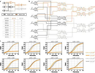
The rule 110-rule 124 DNA circuit generated by the seesaw compiler implements
dual rail logic with six layers consisting a total of 78 initial DNA species (fig.2.3c). We then use the Mathematica code generated by the compiler to simulate the
de-signed circuit to predict the expected behavior for 8 different inputs under ideal
experimental conditions (fig.2.3c). Finally, the compiler designed DNA sequences for the individual circuit components were purchased unpurified. The circuit was
constructed using the unpurified DNA strands with no further in-house
purifica-tion. Overall, the seesaw compiler provided an extremely easy and efficient way to
automate the design process. On the experiment side, using unpurified DNA
com-ponents meant additional noise introduced by synthesis and stoichiometric errors
which can pose a challenge to build large-scale circuits. Hence, we took a
bottom-up approach in building this system, beginning by testing its simplest functional
a c b 𝑅124 𝑅110 𝐿 𝐶 𝑅 𝑅1240 𝑅1241 𝑅1100 𝑅1101
𝐿𝐶𝑅 = 100
𝐿𝐶𝑅 = 001 𝐿𝐶𝑅 = 000
𝐿𝐶𝑅 = 101 𝐿𝐶𝑅 = 110 𝐿𝐶𝑅 = 111
𝐿 𝐶 𝑅 𝑅124 𝑅110
0 0 0 0 0
0 0 1 0 1
0 1 0 1 1
0 1 1 1 1
1 0 0 1 0
1 0 1 1 1
1 1 0 1 1
1 1 1 0 0
Rule 110 Rule 124 𝐿0 𝐿1 𝐶0 𝐶1 𝑅0 𝑅1 𝑅1240 𝑅1241 𝑅1100 𝑅1101
𝐿𝐶𝑅 = 010 𝐿𝐶𝑅 = 011
[image:28.612.111.501.72.374.2]∧ ∨ ∧ ∨ ∧ ∨ ∧ ∨ ∧ ∨
Figure 2.3: Design of a rule 110-124 circuit using the Seesaw Compiler. a, Gate di-agram and truth table of a digital logic circuit that computes the transition rules 110 and
124 of elementary cellular automata.b, Seesaw gate diagram of the equivalent DNA strand
displacement circuit. Each seesaw node connected to a dual-rail input implements input
fan-out. Each pair of seesaw nodes labeled∧and∨implements a dual-rail AND and OR
gate, respectively. Each pair of dual-rail AND and OR gates implements an AND, OR or
NAND gate in the original logic circuit. Each dual-rail output is converted to a fluorescence
signal through a reporter, indicated as a half node with a zigzag arrow. Each circle and dot
inside a seesaw node indicates a double-stranded threshold and gate molecule, respectively.
Each dot on a wire indicates a single-stranded fuel molecule. c, Simulations of the DNA
strand displacement circuit using the previously developed model for purified seesaw
cir-cuits. Trajectories and their corresponding outputs have matching colors. Overlapping
trajectories were shifted to be visible. Dotted and solid lines indicate dual-rail outputs that
represent logic OFF and ON, respectively. For example, when inputLC R= 001, meaning
L0, C0 andR1 were introduced at a high concentration and L1, C1 and R0 at a low
con-centration, two output trajectoriesR1240andR1101reached an ON state and the other two
output trajectories R1241 and R1100 remained in an OFF state, indicating that the output
was computed to be 0 and 1 for rule 124 and 110, respectively. Simulations were performed
at 1×= 50 nM — the compiler recommended standard concentration for large-scale
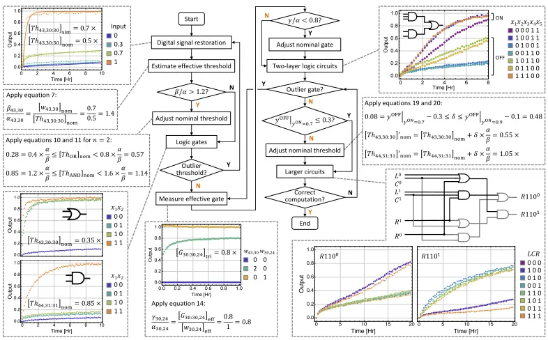
2.2 Calibrating effective concentrations.
To begin building the circuit bottom-up, we first tested the digital signal restoration,
which involves signal amplification and thresholding. The expected circuit behavior
using the seesaw compiler predicts that input signal less than the threshold should
be cleaned up to an ideal OFF state, and input greater than the threshold should be
amplified to an ideal ON state eq. (2.1). The seesaw circuit has the digital signal restoration as a component in every logic gate.
y =
1 x >t h
0 x ≤ t h
(2.1)
At the molecular level, the digital signal restoration process consists of two basic
reactions: catalysis and thresholding. Catalysis is implemented with two toehold exchange pathways that release free output strandswi,k from double-stranded gate
moleculesGi:i,k, using the input strandswj,ias a catalyst (Supplementary fig.2.13a):
wj,i+Gi:i,k
ks
−→wj,i+wi,k (2.2)
Catalysis can be used for signal amplification, since a small amount of input can
trigger the release of a much larger amount of output.
Thresholding is implemented with double-stranded threshold moleculesT hj,i:i
con-suming the input at a much faster rate (kf ks) than the input acting as a catalyst (Supplementary fig.2.13b):
wj,i+T hj,i:i kf
a
d
c b
𝑇ℎ53,5:5 sim= 0.5 × 𝑇ℎ53,5:5 nom= 0.5 ×
53 f 5 2 2 𝑥1 𝑥2 18 22
-1.2 1 𝑦
6 -1.5
𝑇ℎ53,5:5 nom= 0.85 ×
10 f 1 2 2 𝑥1 𝑥2 21 27
-.6 1 𝑦
23 -1.5
𝑇ℎ10,1:1 nom= 0.35 ×
53 f 5 2 Input 𝑤53,5
-.5 1 𝑦
6 -1.5
𝑥1
𝑥2 OR 𝑦
𝐺1:1,23 tri= 0.8 ×
10 1
𝑥1 𝑥2
1 y
23 -1.5
e
𝑥1
𝑥2 AND 𝑦 Input 0 0.3 0.7 1 Input 0 0.3 0.7 1 Input 0 0.3 0.7 1
𝑥1𝑥2 0 0 0 1 1 0 1 1
𝑥1𝑥2 0 0 2 0 0 1
𝑇ℎ53,5:5 sim= 0.7 × 𝑇ℎ53,5:5 nom= 0.5 ×
Figure 2.4: Calibrating effective concentrations. a, Simulations and b, experimental
data of digital signal restoration. c, Estimating effective threshold concentration by fitting
simulations to the data obtained. d, OR and AND logic gates constructed using adjusted
nominal threshold concentrations. e, Estimating effective gate concentration. Data show
steady state fluorescence level. 1× = 100 nM. Here and in later figures, all output signals
in the data were normalized using the minimum fluorescence signal (the first data point) of
an OFF trajectory as 0, and the maximum fluorescence signal (the average of the last five
data points) of an ON trajectory as 1.
The Seesaw Compiler was to used simulate digital signal restoration with threshold
molecule concentration of 0.5× (1× = 100 nM), with multiple input signal con-centrations ranging from 0× to 1×. The expected behavior (fig. 2.4a) resulted in an OFF state with an input less than the threshold molecule concentration (i.e, 0× and 0.3×), cleaned up by eq. (2.3). An input greater than the threshold molecule concentration (i.e, 0.7×and 1×), resulted in an ON state, amplified via eq. (2.2). However, the observed circuit behavior (fig. 2.4b) input 0.7× that was more than the threshold concentration of 0.5×did not reach the ideal ON state. The difference between expected (simulation) and observed (data) circuit behaviors suggests that
the effective concentration of an unpurified threshold species, compared to that of
an unpurified signal species, was higher than expected.
In order to resolve the above conflict, we needed to investigate the source leading to this concentration difference. Typically, spectrometric absorbance at 260 nm is
used to quantify the nominal concentration of DNA species. This measured
con-centration can be greater than the effective concentration of the species that can
actively take part in the desired reaction. Assuming that the DNA sequences are
correctly designed, synthesis errors including nucleotide insertion, deletion and
nominal concentration. To estimate the effective concentration of unpurfied DNA
molecules, we defined the ratio of effective (eff) to nominal (nom) concentrations
of an arbitrary signal, threshold and gate molecules,
αj,i = [wj,i]eff
[wj,i]nom
(2.4)
βj,i = [T hj,i:i]eff
[T hj,i:i]nom
(2.5)
γi,k = [Gi:i,k]eff
[Gi:i,k]nom
(2.6)
The digital signal restoration is composed of an input signal, threshold and gate:output
molecule which triggers a reporter molecule for fluorescence readout. Hence the
ab-solute concentrations of each of the species cannot be measured individually.
Fur-ther, the absolute concentrations will only affect the speed of the reactions, but does
not guarantee the correctness of computation. We therefore proceeded to compare
the data (fig. 2.4b) with simulation (fig. 2.4a) to estimate the effective concentra-tion of an unpurified threshold species, compared to that of an unpurified signal
species. By changing the threshold value in the simulation to 0.7× the simulation results agreed with the experiment results. From this, we inferred that the effective concentration of the signal was similar to that of the signal for nominal
concentra-tion of threshold [T h53,5:5]nom =0.5×and nominal concentration of the input signal [w53,5]nom = 0.7×.
Thus the threshold to signal ratio can be calculated as:
β53,5
α53,5 =
[T h53,5:5]eff [T h53,5:5]nom
× [w53,5]nom [w53,5]eff = [w53,5]nom
[T h53,5:5]nom
[T h53,5:5]eff=[w53,5]eff
= 0.7 0.5 = 1.4
(2.7)
The effective concentration of unpurified threshold molecules may be higher than
the signal molecules when the nominal concentrations are the same because error
introduced during synthesis. The process of chemical synthesis involves the cou-pling of nucleotides sequentially, and the coucou-pling efficiency in each step is less than
of synthesis error is higher in the signal molecule than in the components of the
threshold molecule.
Signal restoration experiments were performed on additional components of the
rule110-rule124 circuit and the threshold to signal ratio β/α = 1.4 was consistent
for different threshold and signal molecules (Supplementary fig.2.14). Hence this ratio was used to adjust the nominal thresholds for computing 2 and 3-input AND
and OR logic.
An upstream integrating node coupled with a downstream amplifying node is used
to compose a seesaw logic gate. Ideally, an integrating node outputs the sum of all inputs:
y =
n
X
i=1
xi (2.8)
A two-input logic function can be computed as:
y=
1 x1+x2 >t h
0 x1+x2 ≤ t h
(2.9)
Assuming that an ideal OFF state is [0,0.2] and an ideal ON state is [0.8,1],t h =
0.6 will compute logic OR andt h = 1.2 will compute logic AND, if the effective
concentrations of the threshold and input signals are comparable to each other (i.e.
β/α = 1).
Since β/α , 1 for unpurified threshold and signal molecules, we can take this ratio
into consideration while calculating the lower and upper bounds of the nominal
threshold for ann-input logic gate:
0.2n× α
β ≤ [T hOR]nom < 0.8×
α
β (2.10)
[(n−1)+0.2]× α
β ≤ [T hAND]nom < 0.8n×
α
β (2.11)
Using β/α = 1.4, we chose a nominal threshold of 0.35× and 0.85× for two-input OR and AND gate, respectively, and 0.4× and 1.6× for three-input OR and AND gate. Experiments of the logic gates showed desired behaviors ( fig.2.4d and Supplementary fig.2.15).
An alternative approach for adjusting the nominal threshold is to use the following
equations:
[T hOR]nom = 0.6×
α
[T hAND]nom =[(n−1)+0.2]×
α
β (2.13)
Compared to choosing a nominal threshold based on the lower and upper bounds,
this approach is less flexible but simpler.
Similarly the ratio between γ and αfor a gate releasing a signal can be estimated
using an experiment that compares the fully triggered (tri) concentration of the gate
with the signal when their nominal concentrations are the same. For example, the data in fig.2.4e showed that [G1:1,23]tri =0.8×when [G1:1,23]nom =[w1,23]nom =1×. Thus the gate to signal ratio can be calculated as:
γ1,23
α1,23 =
[G1:1,23]eff [G1:1,23]nom
× [w1,23]nom [w1,23]eff = [G1:1,23]eff
[w1,23]eff
[G1:1,23]nom=[w1,23]nom
= 0.8 1 = 0.8
(2.14)
Additional gate calibration experiments suggested that the ratio γ/α = 0.8 was
consistent for different gate and signal molecules (Supplementary fig.2.16). We suspect that due to synthesis errors in gate molecules, not all gates can successfully
release a signal, which is why an unpurified gate has a lower effective concentration compared to a signal.
As signal restoration was built in within every logic gate to accept an ON state of
[0.8,1], we decided not to make any adjustment for nominal gate concentrations if
γ/α ≥ 0.8. Otherwise, nominal concentration of an amplifying gate and ann-input integrating gate can be adjusted as:
[GAMP]nom =1×
α
γ (2.15)
[GINT]nom = n×
α
γ (2.16)
Importantly, the values ofα, βandγshould depend on the strand quality, and thus
could vary with different DNA synthesis providers, procedures, and batch orders. It
a b c ON OFF ON OFF 𝐺18:18,53 tri= 0.8 ×
𝐺22:22,53 tri= 0.44 × 18
f 53
2
1 2 𝑦
6
-1.5
34 𝑥1
22
f 53
2
1 2 𝑦
6
-1.5
39 𝑥2 𝐺22:22,53
𝐺18:18,53
𝐺22:22,53 nom′ = 1.8 × 53
f 5
2
2 -1.2 1 𝑦
6
-1.5
𝑇ℎ53,5:5 nom= 0.85 × 39 f 22 2 2 𝑥4 𝑥5 29 35 -.6 1 34 f 18 2 3 𝑥1 𝑥3 28 37 -.6 1 𝑥2 33
𝑇ℎ39,22:22 nom= 0.35 ×
𝑇ℎ34,18:18 nom= 0.4 × 𝐺18:18,53
𝐺22:22,53
𝑥1110
𝑥2110
𝑥3100
𝑥4001
𝑥5001
𝑦 110
001
0
𝑥3
𝑥3
𝑥1𝑥2𝑥3
0 2 0 2 1
𝑥1𝑥2𝑥3𝑥4𝑥5𝑦
1 1 1 0 0 0 0 1 1 1 0 1 1 0 1 0 1 1 1 1 0 0 0 0 0 0 1 1 1 1 0 1 0 1 0 1 1 0 0 0 1 1 0 0 0 1 1 0
𝑥1𝑥2𝑥3𝑥4𝑥5𝑦
[image:34.612.57.557.72.313.2]1 1 1 0 0 0 0 1 1 1 0 1 1 0 1 0 1 1 1 1 0 0 0 0 0 0 1 1 1 1 0 1 0 1 0 1 1 0 0 0 1 1 0 0 0 1 1 0
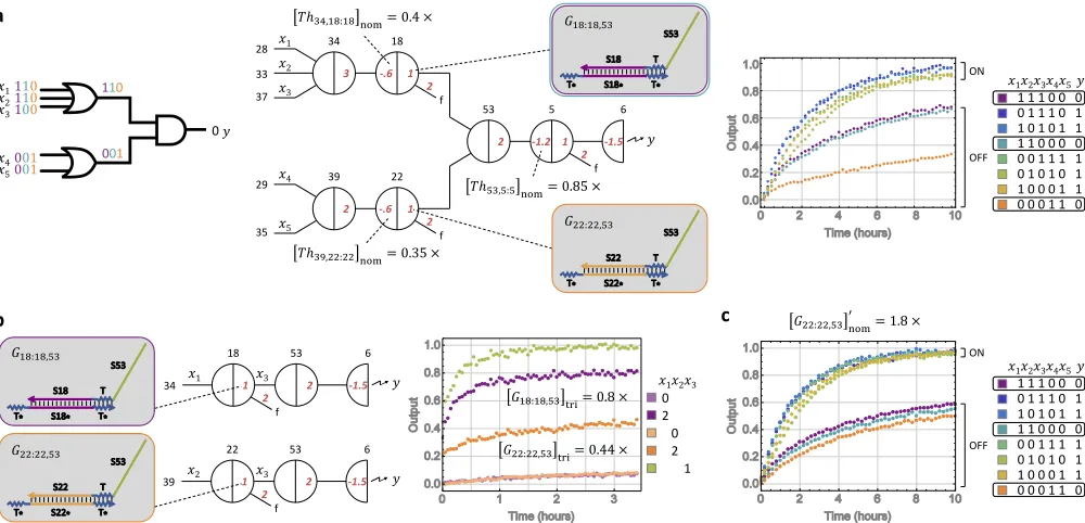
Figure 2.5:Identifying an outlier gate. a, Logic circuit diagram, seesaw circuit diagram, and experimental data of a two-layer logic circuit.b, Measuring the effective concentrations
of the gate species. Three independent circuits were used to measure the effective
concen-trations of two gates fully triggered by x1and x2, respectively, comparing to the effective
concentration ofx3(using signal strandw18,53).c, Experimental data of the two-layer logic
circuit using adjusted nominal gate concentration. 1×=100 nM.
2.3 Identifying outliers.
Next we move to test a larger part of the designed circuit by cascading an upstream
layer of OR gates into the single AND gate already tested (fig.2.4d). The upstream OR gates were not tested individually, but the nominal threshold concentration of the 3 and 2-input OR gate was calculated using the measured ratio from the digital
restoration gate eq. (2.10). The components of this two layer logic circuit is part of the rule 124 sub-circuit. The expected circuit behavior was plotted showing that
the output should remain OFF when only one of the upstream OR gates is ON. The
observed circuit behavior showed that the output was reasonably OFF when one
upstream OR gate was ON (x1 = x2 = x3 = 0;x4 = x5 = 1), but was half ON
when the other upstream OR gate was ON (x1 = x2 = x3 = 1;x4 = x5 = 0)
(fig. 2.5a). This experimental result suggests that the two inputs to the AND gate from the upstream OR gates were not symmetrical, i.e , it there was a variation in the effective concentrations of the upstream unpurified gate species leads to unbalanced
The two upstream OR gates were then tested to verify ifγ/α ,0.8 (eq. (2.16). The data in fig.2.5b shows a gate calibration experiment to check for outlier gates. The ratios resulted in γ18,53/α18,53 = 0.8× for one gate and γ22,53/α22,53 = 0.44× for another, highlighting the outlier gate.
Lower concentration of one of the gates could be the result of synthesis error in the
strands used to compose the gate. There is a higher probability that the synthesis of
DNA strand for this particular gate were lower than average quality, than the DNA
strands for the other gate being higher than average quality.
The threshold or the gate concentration of this outlier could be modified using its threshold to signal ratio (β/α) or gate to signal ratio (γ/α), the common nominal
concentration described in the previous section, and the common ratio for other
thresholds and gates:
[T hj,i:i]0nom = [T hj,i:i]nom ×
αj,i
βj,i ×
β
α (2.17)
[Gi:i,k]0nom =[Gi:i,k]nom×
αi,k
γi,k ×
γ
α (2.18)
In this case, the unbalanced wires do not completely reduce the ON/OFF gap and
can therefore be fixed by increasing the downstream threshold ([T h53,5:5]nom). But in other cases, unbalanced wires could result in significantly reduced ON/OFF gaps
that cannot be resolved by increasing the downstream thresholds. In order to find a
universal solution that can be applied across the entire circuit, we measure the
dif-ference between the effective concentrations of unpurified gate species that caused
the unbalanced wires. In order to do this, we first connect the downstream see-saw node directly to a reporter. We then remove the threshold and fully trigger the
gate in question with excess input signals (2×) and compare the triggered levels of the two gates (fig. 2.5b). To balance the two wires, we could either increase the nominal concentration of one gate ([G22:22,53]nom) or decrease the nominal concen-tration of the other ([G18:18,53]nom). We chose the former, because the triggered output of [G18:18,53]nom was found to be equal to the output triggered by signal
w18,53, while the triggered output of ([G22:22,53]nom) was much lower than then out-put triggered by w22,53. We adjusted the nominal concentration of unpurified gate [G22:22,53]0nom = 1/0.44×0.8 = 1.8×. Hence our solution to the challenge of un-balanced wires is to measure the difference between the effective concentrations of
concentrations of them accordingly. By implementing this change in gate
concen-tration, we observed that the ON trajectory was at an ideal high fluorescence state
(fig. 2.5b). The OFF trajectories were lower, at roughly the same level for diff er-ent combinations of inputs, but were not at an ideal low fluorescence state. This
required further tuning of the unpurified cascaded sub-circuit.
2.4 Tuning circuit output.
The downstream AND gate when tested in isolation showed expected computation
( fig.2.4d) with significant ON/OFF separation, but cascading the AND gate with two upstream OR gates decreased the ON/OFF signal gap of the circuit. The
ex-pected circuit behavior is that the output should remain OFF when either upstream
OR gate is OFF. However, erroneous ON cases were observed experimentally when
one of the OR gates was expected to be OFF while the other OR gate had more than
one input being ON. This suggests that unpurified circuits are noisier than expected,
compared with purified circuits [25], and the behavior becomes less robust with in-creasing number of layers.
One possible reason for the increased noise in unpurified circuit is stoichiometry.
All gate molecules were prepared by annealing equal proportion of top signal strand
and bottom sink strand constituting the gate molecule. Both top and bottom strands
have toeholds and migration domains that can interfere with downstream
compo-nents if present in excess. The equal proportion was assumed by the concentration
information provided by the oligo vendor. However, small discrepancies in pipet-ting volumes or concentration accuracy could easily off-set the stoichiometry of
the two strands. In-house purification of such annealed complexes remove excess
unbound strands. In the absence of this purification step, even a small excess of
strands would result in undesired output release in down stream gates, introducing