Structured Abstract:
Purpose – This work presents an investigation of Halbach array effects in surface mounted permanent magnet machine (SMPM) in terms of both self-sensing and torque capabilities. A comparison between a conventional SMPM, which has radially magnetized rotor, and a Halbach machine has been carried out.
Design/methodology/approach – The geometric parameters of the two machines have been optimized using GA with looking pareto. The performance of the machines’ geometry has been calculated by finite element analysis (FEA) software, and two parametric machine models have been realized in Matlab coupled with the FEA and GA toolboxes. Outer volume of the machine, thus copper loss per volume has been kept constant. The pareto front approach, which simultaneously considers looks two aims, has been used to provide the trade-off between the torque and sensorless performances.
Findings – The two machines’ results have been compared separately for each loading condition. According to the results, the superiority of the Halbach machine has been shown in terms of sensorless capability compromising torque performance. Additionally, this paper shows that the self-sensing properties of a SMPM machine should be considered at the design stage of the machine.
Originality/value – A Halbach machine design optimisation has been presented using pareto optimal set which provides a trade-off comparison between two aims without using weightings. These are sensorless performance and torque capability. There is no such a work about sensorless capability of the Halbach type SMPM in the literature.
Keywords:
Halbach array, sensorless control, design optimization, permanent magnet machine, pareto front, genetic algorithm.
I. INTRODUCTION
The sensorless control of AC motors is desirable in many applications in terms of cost and reliability due to the lack of motion sensors. In order to realize sensorless control, the rotor position must be estimated using model-based or saliency-based methods. Model-based methods rely directly or indirectly on the back-EMF induced by the rotor magnets in the stator windings of the machine. In low speed applications, due to the decreasing magnitude of back-EMF, sensorless performance becomes weak. Saliency based hf signal injection methods have been proposed for low/zero speed applications (Lorenz, 2006; Yang and Lorenz, 2011; Fernandes et al., 2010; Al-Nabi et al., 2013; Zhu and Gong, 2011). In this method, hf voltage is injected and the hf currents are modulated by the machine’s magnetic saliency from which the rotor position can be derived. This saliency can either be in the rotor itself due to the rotor geometry or as a result of iron saturation in the rotor or stator due to the
synchronously rotating magnetic flux. This saliency can be tracked by processing the current response to a test voltage signal injection overlaid on the main PWM excitation. However, the robustness (ie. no loss of saliency) and the quality of this position signal depends on the machine geometry and this has prevented industrial application (Caner et al., 2015). The importance of industrial drives can be increased for low/zero speed applications by manufacturing machines compatible with these methods.
Saliencies resulting from the difference of incremental inductances in the direct and quadrature axis are the main factors that influence the sensorless performance for techniques based on high frequency injection. In SMPM machines, these are mainly a function of the non-linearity of the magnetic material as the machines have an inherently negligible geometric saliency. A major issue with controlling the machines at a high load arises due to the differential saliency tending to decrease with increased machine loading (Arellano-Padilla et al., 2010). Therefore, the issue of performance loss at high loading levels should be taken into consideration at the design stage of the machine.
In terms of reliability, FEA-based analysis is used to calculate performance indicators of the motors in this study. In terms of computation time, an analytical model was preferred in some studies (Cvetkovski et al., 2010; Zare et al., 2012; Hasanien, 2011), but the model has many simplifications and needs to be verified using FEA. These indicators are evaluated by an optimization technique which can be deterministic or stochastic. In order to avoid catching local minimum stochastic techniques are preferred. A number of papers have been published looking at machine design-coupled FEA parametric models embedded with stochastic optimization techniques (Abbaszadeh et al., 2011; Idoumghar et al., 2009; Wrobel and Mellor, 2006). Beside others like particle swarm optimization (PSO), tabu search, and response surface (RS) algorithms, a FEA coupled genetic algorithm (GA) has been successfully used as an optimization method for PM synchronous machines (Bianchi and Bolognani, 1998;
Chai and Pollock, 2002; Łukaniszyn et al., 2004;Wrobel and Mellor, 2004; 2005; 2008).
When the design opimization is introduced as a multiobjective problem, a pareto solution can be used to determine the optimal point at which may not be said one being absolutely better than another. The pareto technique has gained attention in PM design studies over the last decade (Touati et al., 2010; Duan and Ionel, 2013; Ranjan et al., 2013; Sizov et al., 2011; Andersen and Santos, 2012; Pellegrino and Cupertino, 2010; Duan et al., 2013).
PM machines with the Halbach structure have been compared with radial and other types of arrays and have showed superiority (Dwari et al., 2009; Jang et al., 2001; Kataoka et al., 2012; Mellor and Wrobel, 2005; Zhu et al., 2002). Also, design optimization studies with GA have been published by Huang et al., (2008) and Tavana & Shoulaie,
Design Optimization of Halbach Array
(2009). A study related to sensorless performance using GA and pareto is not yet mentioned in the literature.
In this paper, the performances of two SMPM motor structures are optimized in terms of both torque and self- sensing capabilities. One is with a radial magnet array and the other is with a Halbach magnet array. Each motor is simulated via FEA using Matlab aided parametric modeling. Eight design variables were optimized using GA with looking pareto.
As a first step, the pareto optimal results by compromising between torque and torque ripple have been presented for the two machines. As a second step, GA optimization with looking pareto has been applied to the two machines in order to improve torque and self-sensing capability. It is shown that the Halbach machine can be designed with superior performance per volume in terms of both torque and self-sensing when compared with a radially magnetized SMPM.
II. SALIENCY CONDITIONING FOR SELF-SENSING MACHINES
The parameters used for representing the saliencies in PM machines are the dq incremental inductances defined as:
;
q;
qd d
d q dq
d q q d
L
L
L
i
i
i
i
ψ
ψ
ψ
∂
ψ
∂
∂
∂
′
=
′
=
′
=
=
∂
∂
∂
∂
(1)where
ψ
d,q,i
d,q are standard rotating synchronous frame variables obtained from measured or derived 3-phase quantities by the appropriate transformations. In an ideal machine, the dq inductances of (1) should be independent of the circumferential position θ. In practice, they are not due to saturation and other space harmonics. It was shown by Arellano-Padilla et al., (2010) that the characteristics of (1) have a strong influence on the quality of the sensorless control of the particular machine, i.e. its self-sensing capability. The three quality criteria are:max{∆L( , )
θ
iq =Lq′( , )θ
iq −Ld′( , )}θ
iq (2) min{Lq′( , )θ
iq pp}, min{Ld′( , )θ
iq pp} (3)min{Ldq′ ( , )}
θ
iq (4)where the bar denotes average inductance over θ = 0 →2π electrical. The differential inductance condition (2) describes the requirement for saliency under all load currents. This is a serious issue since IPMSM exhibit decreasing differential saliency with loading, and loss of saliency can occur within operational iq currents. For SMPM machines, condition (2) also needs to be maximised due to the need to increase resolution and accuracy in the light of the generally small value of saliency exhibited. Condition (3) minimizes the peak-peak ripple value of the inductance over θ and represents the requirement for a sinusoidal circumferential inductance distribution for a given rotor position. This leads to a clean estimated positional signal resulting in greater bandwidths for the sensorless speed and position control loops. In practice, it is found that the ripple in Ld′ and
L
q′
change in similar proportions with machine currents and machine variables, so it is not critical which measure is taken.Condition (4) represents the degree of dq axis coupling and for the rotor position estimator results in an estimated angle error that is a function of
i
d,q. In practice, this error can be compensated by simple signal processing during real-time operation so that the minimization of (4) is not of prime importance. This paper will consider maximizing (2) and minimizing (3) within the GA.III. RADIAL VS.HALBACH MAGNET ARRAY SMPM MACHINE
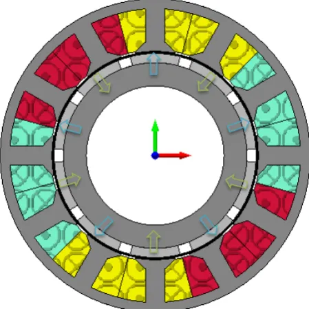
In SMPM machines, magnets which have equal span are equally spaced on the surface of the rotor. In this study, the magnets of SMPM are fully on the surface. Their directions of magnetization are radially and alternate outwardly and inwardly (Figure 1).
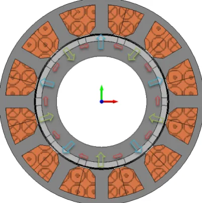
[image:2.595.314.539.380.605.2]In Halbach machine, magnet segments are mounted on the rotor surface as a wheel without any space between them. The magnet wheel consists of adjacent main and auxiliary parts. The main parts are radially magnetized just like SMPM. The directions of magnetization in the auxiliary parts are tangential. If two auxiliary parts are adjacent to a main part which has outward direction, the directions of magnetization of the auxiliary parts are towards each other. If two auxiliary parts are adjacent to a main part which has inward direction, the directions of magnetization in the auxiliary parts are away from each other.
Figure 1. Directions of magnetization in classical SMPM
This is called a Halbach magnet array and is shown in Figure 2. The Halbach array cancels the flux on one side and strengthens the flux on the other side.
By applying the circular Halbach array magnets to a PM motor (Figure 3), rotor back iron can be made thinner and the rotor inertia can be reduced. Hence, the rotor structure can be hollowed and can be designed for high acceleration application, as well as low core loss (Sadeghi and Parsa, 2011; Zhu, 2007).
obtained without recourse to skewing of the stator (Li and Xia, 2008).
Figure 2. Flux lines of Halbach magnet array
[image:3.595.47.291.84.225.2]In stator structure of both machines, a double layer concentrated winding configuration was used. It has good impacts on saliency-based sensorless control (Arellano-Padilla et al., 2010). Important features of the fractional slot structure were mentioned in the study of Caner et al., (2011).
Figure 3. Directions of magnetization in Halbach machine
The flux distribution of the classic SMPM and Halbach machine were given in Figures 4 and 5. Dimensions of these figures are taken as optimal design results in this study. It is shown that rotor hole is larger and stator radial thickness is smaller in Halbach machine. Also rotor back iron thickness can be reduced without any performance loss due to Halbach flux cancellation. According to these figures, radial thickness results of the rotors are 10.8 mm and 6.8 mm for SMPM and Halbach machines respectively.
[image:3.595.324.532.296.503.2]Figure 4. Flux distribution of classical SMPM
Figure 5 Flux distribution of Halbach machine
IV. PARAMETRIC MODELLING OF PM MOTOR
Radial and Halbach array-based three phase SMPM machine geometries have been created and analysed with Magnet 2D, a commercial FEA software package. All the machine design data has been created using external scripting which is written in Matlab. In order to make a proper comparison, the dimensions of the two machines are assumed to be the same. Thus some assumptions used for the motor geometries have been given below.
• fixed outer radius, 67.5 mm • fixed slot/pole combination, 12/10 • fixed air gap length, 1mm
• fixed axial length, 100mm
• fixed copper loss,165W at nominal loading
[image:3.595.67.268.338.540.2]as 0.5. The number of turns per coil of the stator phase windings is 34 and 4 coils have been used for each phase. Because magnet software doesn’t consider the fill factor, copper loss can be correctly calculated via Matlab codes using the equations given in (5-8). The geometrical dimensions of the end winding have been estimated using the coordinate points of the slots from the FEA parametric model. The end winding length was estimated using these coordinates and assuming an end winding length proportional to the perimeter distance between the coil side connections..
2 (
)
coil phase coil turn m ew
l
=
n
⋅
n
⋅
n
⋅ ⋅
l
+
l
(5)(
coil)
total
f slot turn
l
R
k
A
n
ρ
⋅
=
(6)2 2
d q
I
I
I
2
+
=
(7)2
cu total
P
=
I
⋅
R
(8)2 slot new q new q ref
slot ref
A
I
I
A
−
− −
−
=
(9)𝑛𝑛𝑝𝑝ℎ𝑎𝑎𝑎𝑎𝑎𝑎R : phase number
𝑛𝑛𝑐𝑐𝑐𝑐𝑐𝑐𝑐𝑐 : number of coil in each phase 𝑛𝑛𝑡𝑡𝑡𝑡𝑡𝑡𝑡𝑡 : number of turn in each slot 𝑙𝑙𝑚𝑚 : motor axial length
𝑙𝑙𝑎𝑎𝑒𝑒 : half perimeter of the end winding 𝑙𝑙𝑐𝑐𝑐𝑐𝑐𝑐𝑐𝑐 : length of all coils
𝑘𝑘𝑓𝑓 : fill factor of slot area 𝐴𝐴𝑎𝑎𝑐𝑐𝑐𝑐𝑡𝑡 : slot area
In order to obtain constant copper loss, current level of the motor should be tuned while slot area changes due the new motor geometry. Reference values of 𝐼𝐼𝑞𝑞 and 𝐴𝐴𝑎𝑎𝑐𝑐𝑐𝑐𝑡𝑡 were found for 6A/mm2 current density and desired copper loss level and new current value calculated using (9).
[image:4.595.279.545.110.392.2] [image:4.595.49.277.176.430.2]The PMs used in this machine are Nd2Fe14B type 40/15 with a residual induction of Br 1.29 T at 20C. Also remanence value of the magnet material decreases due to temperature increase. B-H curve is given for M330-35A non-oriented silicon steel material chosen for the stator and rotor iron cores (Figure 6).
Figure 6. B-H curve of stator and rotor core material
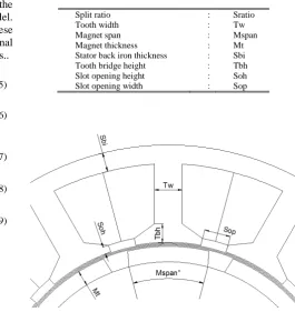
The motor design geometry was created with eight geometric parameters as variables which were then optimized as will be described later on according to different set goals. The first variable is split ratio which indicates the ratio of inner stator
radius to the outer stator radius. All design variables and their abbreviations are listed in Table I. The placement of these variables on the motor is shown in Figure 7.
TABLE I.DESIGN VARIABLES
Split ratio : Sratio
Tooth width : Tw
Magnet span : Mspan
Magnet thickness : Mt Stator back iron thickness : Sbi Tooth bridge height : Tbh Slot opening height : Soh Slot opening width : Sop
Figure 7. Design variables of motor
The design limits of these variables are defined according to pre-design optimization results. Magnet thickness has been limited to 3-4 mm. The y-axis symmetry is used to draw both slot and magnet geometries. Firstly the left and right side of the half-slot parts with 6 points have been drawn and then copied with the angle of 30o due to the number of slots is 12.
Each coordinate has been obtained with polar calculations using angles. Similar processes have been applied for drawing magnet geometry. But this time the angle is 36o, due
to the number of magnets is 10.
In order to obtain maximum torque, a correction should be applied to rotor position. This process is achieved using the rule that sinusoidal flux variation is 90 degrees lag to induced EMF variation.
Because motors have 5 pole pairs and their rotor speed is assumed at 3000 rpm, the mechanical and electrical periods are 20 and 4 milliseconds respectively. Torque period is repeated six times in one electrical period. Thus 0.64 milliseconds are a sufficient simulation period. Besides the minimum simulation period, in order to decrease processing time, the resolution of simulation is important as well. In order to not lose any real variation, it is important to choose the correct values for resolution to obtain meaningful values from the modelling software. Resolution has been chosen as 0.04 ms so as to provide a balance between simulation speed and real variation error.
A non-linear 2D time-stepping simulation is run for each parameter change, with the current level scaled for a fixed copper loss to determine the mean torque, torque ripple and flux variations.
0 2000 4000 6000 8000 10000 12000 0
0.2 0.4 0.6 0.8 1 1.2 1.4 1.6 1.8
H (A / m)
B
(T
e
sla
[image:4.595.62.275.583.728.2]V. GA OPTIMIZATION WITH PARETO FRONT
GA is applied as a Matlab tool and is integrated FEA-based design software. In this study, all the variables were used as genes of the chromosome and pre-defined functions in the GA toolbox were applied to realize genetic operations.
Two fitness functions in (10-11) are used to realize two aims. They are aimed to obtain maximum torque with minimum ripple and good sensorless performance. Referring to these equations; in order to maximize a part of a fitness functions the relevant part has been taken as negative (−) because the GA toolbox tries to minimize the value of these functions.
1
1 2
T R
T Tr
f k k
n n
= − +
(10)
_ _
2
3 4 5
d pp q pp
S D Q
L L
L
f k k k
n n n
′ ′
∆
= − + +
(11)
q d
L L′ L′
∆ = − (12)
In the torque fitness equation (10), T is the mean value of torque variation and Tr is the torque ripple obtained by subtracting the minimum value from the maximum value of the torque variation.
In the saliency fitness equation (11), amplitude of saliency is the inductance difference (12). Lq′ and
L
d′
are mean values which are calculated after three simulations using nominal and two disturbed flux variations. While nominal flux variations are obtained using nominal current, disturbed flux variations are obtained applying small test signals (∆𝐼𝐼𝑞𝑞, ∆𝐼𝐼𝑑𝑑) to the q and d axis currents separately. The inductance variations are calculated using equations in (13) and (14).(
)
1
id
d d d
d
L
i
ψ
∆ψ
′ =
−
∆
(13)(
)
1
iqq q q
q
L
i
ψ
∆ψ
′ =
−
∆
(14)_
d pp
L′ and Lq′_ppindicate the peak to peak difference of the inductance variations versus the position angle for d and q axis respectively. Their calculations are similar with Tr.
Normalization and weighting factors are selected in a certain logic that to provide equalization and to define importance levels for each part of the fitness function (Caner et al., 2015). As an example, estimated optimized values of torque is 30 Nm and its ripple is 1 Nm approximately. In addition, mean torque importance is 0.95 while its ripple importance is 0.05. Chosen values are n1=30, n2=1, n3=0.6, n4=n5=0.2 for normalization and kT=0.95, kR=0.05, kS=0.6, kD=kQ=0.2 for weighting.
The weighted sum nature of fitness functions in (10-11) describes a multi-objective optimization problem (MOP). The optimization aims of each part connected via weighing coefficients often do not agree with each other. Hence, it comes up a requirement of a set of optimal solutions. The compromise of these optimal solutions in the set is important for MOP. This concept leads to the foundation of pareto
optimality (Ghosh and Chakraborty, 2014). Taking into account that all aims, each point in the pareto solution space does not mean the best result. One aim improves while the other worsens.
A pareto optimal solution is a point which provides improvement for every aspects of fitness. All the Pareto optimal solutions play a very important role in MOPs when it comes to the analysis of the trade-off among the conflicting aims. The trade-off between parts of fitness can be observed in the pareto set unless using weighting factors.
In this study, the GA toolbox in the Matlab has been applied with looking pareto firstly for each parts in (10) secondly between (10) and (11). In each application, two aims have been chosen to provide a trade-off. The pareto algorithm gives a solution space between torque and its ripple for the first application and torque capability and sensorless performance for the second.
The parameters of multiobjective optimization using GA are summarized in Table II.
TABLEII.PARAMETERSOFTHEGENETICALGORITHM
Population size : 15 Chromozome size : 8 Maximum generation : 33 Stall generations limit : 20 Crossover fraction : 0,75 Pareto fraction : 0,7 Migration interval : 10 Mutation function : Adaptation feasible
VI. DESIGN OPTIMISATION STUDIES
In this section, design optimization results of the SMPM and the Halbach machine have been presented and compared in order to evaluate performances in terms of torque and sensorless capability. GA optimization has been used with looking pareto optimal set. FEA results have been used to calculate fitness values.
Firstly, design optimization based on pareto analysis has been applied for the two machines by providing the trade-off between torque and percentage of peak to peak torque ripple. In this case, the fitness function used in pareto optimization has two terms. Due to the nature of pareto optimization, this makes it possible to eliminate weighting and normalisation factors.
The pareto optimal set results for the two machines are given in Table III. These results are taken in nominal loading condition from maximum torque to minimum torque ripple points.
TABLEIII.COMPARISON OF TWO MACHINES IN TERMS OF TORQUE CAPABILITY
Radially
Magnetized SMPM Pareto status
Halbach Machine
Pareto status
T
(Nm)
Tr
(Nm) (Nm) T Tr (Nm) 1 33,2372 2,5723 Max
Torque
35,2823 2,5259 Max Torque 2 33,0131 2,3975 35,2823 2,5259
9 30,2750 0,8151 32,1529 1,3030 10 29,4039 0,6348 29,5575 0,2952
11 29,0919 0,5740 Min Tr 29,5575 0,2952 Min Tr
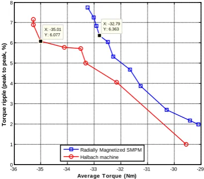
Pareto optimal set results of two machines are obtained and compared inFigure 8. Here the x and y axes indicate torque maximization and torque ripple minimization respectively. Better values for the relevant aim are closer to left bottom corner, 0 and -36. The reason for negative torque values is to convert minimization of GA to maximization. When compared to SMPM machine, torque values for same torque ripple values are rather high in the Halbach machine. The selection of the desired optimal point which trades-off between the two aims is an advantage. The points in number four for both machines have been selected from among the optimal pareto set as optimal points (Table III). These points are also marked in Figure 8.
[image:6.595.45.297.49.82.2]Secondly, in order to increase both the torque and sensorless capabilities of both machines, design optimization based on pareto analysis has been applied by providing trade-off between the two aims. These aims are given in (10, 11) and are also represented as f1 and f2 in Tables IV and V. Although these functions include normalization and weighting coefficient separately, the connection of the two aims has been realized without using any coefficient thanks to pareto. In each fitness calculation of the optimization study, both x1 and x2 loading currents have been used in succession for objectives f1 and f2, respectively. Here, “x1” corresponds to nominal loading current. An advantage of this method has been proposed in the study (Caner et al., 2015). Using x2 current loading for sensorless performance calculation in f1 provides better saliency for a wider operation range.
Figure 8. Graphical representation of pareto optimal sets of two machines for torque capability
It is obvious that torque (Tavg) and the saliency are inversely
proportional from the pareto optimal set points in Figure 9. Both based on the results and according to the nature of the pareto front, number 8 ought to be chosen as the optimal points in both Tables. But if saliency values above 0.5 are acceptable for good sensorless control, the other points can be chosen at the expense of less torque. In this situation, numbers 2 and 3 can be selected as optimum points. This second selection allows us to benefit from 1 and 1.75 Nm
more torque for the SMPM and the Halbach machine, respectively.
TABLEIV.RADIALLY MAGNETIZED MACHINE OPTMIZATION RESULTS IN TERMS OF OVERALL PERFORMANCE
x1 current loading x2 current loading
T Tr f1 ΔL Ld_pp Lq_pp f2
1 33,4904 1,3119 -0,9949 0,2874 0,2912 0,2201 0,2239
2 32,3778 1,5080 -0,9499 0,5680 0,6051 0,1614 0,1985
3 32,1027 1,3781 -0,9477 0,5817 0,6153 0,1302 0,1638
4 32,0667 1,4918 -0,9409 0,6298 0,5866 0,1562 0,1131
5 31,8276 1,4745 -0,9342 0,6417 0,5919 0,1276 0,0778
6 31,8276 1,4745 -0,9342 0,6417 0,5919 0,1276 0,0778
7 31,5288 1,4146 -0,9277 0,6690 0,5645 0,0991 -0,0054
8 31,3911 1,3956 -0,9243 0,6796 0,5486 0,0958 -0,0351
9 29,7744 1,6082 -0,8624 0,7601 0,5071 0,1036 -0,1494
10 29,8705 2,1502 -0,8384 0,7542 0,5108 0,0747 -0,1687
TABLEV.HALBACH MACHINE OPTMIZATION RESULTS IN TERMS OF OVERALL PERFORMANCE
x1 current loading x2 current loading
T Tr f1 ΔL Ld_pp Lq_pp f2
1 34,7593 2,1331 -0,9941 0,4380 0,4132 0,2124 0,1876
2 34,7876 2,2175 -0,9907 0,4342 0,3988 0,2042 0,1688
3 34,3145 1,9256 -0,9903 0,6482 0,4435 0,2229 0,0181
4 34,2256 2,1228 -0,9777 0,6828 0,4365 0,2296 -0,0167
5 34,1693 2,2588 -0,9691 0,7326 0,4266 0,2287 -0,0773
6 34,2173 2,2931 -0,9689 0,7313 0,4258 0,2211 -0,0845
7 32,5793 1,7551 -0,9439 0,7917 0,4638 0,1916 -0,1363
8 32,5616 1,9891 -0,9317 0,8012 0,4712 0,1213 -0,2087
9 32,4088 1,9562 -0,9285 0,8079 0,4650 0,1108 -0,2322
10 31,7303 2,0544 -0,9021 0,8350 0,4700 0,0908 -0,2742
[image:6.595.310.543.114.303.2]11 30,7334 2,3926 -0,8536 0,8915 0,4543 0,1053 -0,3319
Figure 9. Selection of four points from pareto optimal sets of two machines
-36 -35 -34 -33 -32 -31 -30 -29
0 1 2 3 4 5 6 7 8
X: -32.79 Y: 6.363
Tor
que
r
ipple
(
pe
a
k
t
o pe
a
k
, %
)
Average T orque ( Nm)
X: -35.01 Y: 6.077
Radially Magnetized SMPM Halbach machine
-1 -0.98 -0.96 -0.94 -0.92 -0.9 -0.88 -0.86 -0.84 -0.82 -0.4
-0.3 -0.2 -0.1 0 0.1 0.2 0.3
X: -0.9499 Y: 0.1985
f2
(
S
en
so
rl
ess p
er
fo
rm
an
ce)
f
1 (Torque capability)
X: -0.9903 Y: 0.01811
X: -0.9243 Y: -0.03514
X: -0.9317 Y: -0.2087
Radially Magnetized SMPM Halbach machine
HALBACH2
SMPM2
SMPM1
[image:6.595.64.270.449.629.2] [image:6.595.316.528.587.758.2]Computation time of these multiobjective optimizations varies between 16-27 hours and 32-87 hours for torque capability and overall performance respectively.
Design optimization results belong to four machines indicated as four selected points were given in Table VI. SMPM1 and Halbach1 are names of the designs which belong to the trade-off points of two aims according to pareto. SMPM2 and Halbach2 are other design points which are selected for a bit more torque. The performance of these two groups should be evaluated in itself.
In x1 current, saliency values of the two machines in each group are similar. Although torque performances in the Halbach machine group are better, its ripples are higher than that of SMPM machines.
In x2 current, both the torque and sensorless capabilities of the Halbach machines seem superior to SMPM design.
In x3 current, the highest loading condition, the torque performances of the Halbach designs are much higher than the SMPM machines. But more torque leads to more torque ripples. It is also seen that sensorless performance is under 0.5 in group 1 and is almost disappeared in group 2. Additionally, it is shown that the copper loss remained constant in each loading condition. The saliency has the best values in x0.1 loading but torque ripple rate is worse than the other loading conditions.
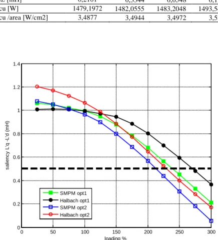
Figure 10 shows the saliency performances of the designs when load is varied. Comparing to saliency variations to each 25% load increase in group 1 shows that saliency is decreasing slowly and is adequate for the wider loading range. If the acceptable value of the saliency is considered 0.5, the saliency disappears slightly above the 200% loading for group 2. Beside the Halbach designs demonstrate superior saliency for high loading in each group.
TABLEVI.COMPARISON OF TWO OPTIMIZED MACHINES IN TERMS OF THREE LOADING CONDITIONS
SMPM1 Halbach1 SMPM2 Halbach2
Variable
names&limits Optimized values of geometric design variables
Sratio 0,62-0,7 0,66 0,67 0,64 0,66
Tw 6-10 (mm) 7,72 7,84 8,13 8,44
Mspan 130 o -150o 146,80 143,63 148,04 145,29
Mt 3-4 (mm) 3,92 3,79 3,83 3,82
Sbi 3-7 (mm) 5,93 5,51 5,94 4,33
Tbh 3-6 (mm) 4,53 4,06 4,76 4,62
Soh 0,1-0,8 (mm) 0,39 0,30 0,28 0,36
Sop 2-10 (mm) 7,11 6,64 6,72 7,12
Performance
indicators Nominal (x0,1) loading conditions results at 20
oC
𝑇𝑇�[Nm] 2,9580 3,2711 3,1432 2,9992
Tr [Nm] 0,5399 0,9419 0,5088 1,2131
Ld_pp [mH] 0,2088 0,0835 0,3213 0,1731
Lq_pp [mH] 0,2312 0,3331 0,2557 0,2469
ΔL [mH] 1,0650 1,2102 1,0822 1,0043
Pcu [W] 1,6436 1,6595 1,6480 1,6467
Pcu /area [W/cm2] 3,87e-3 3,91e-3 3,89e-3 3,88e-3
Performance
indicators Nominal (x1) loading conditions results at 20
oC
𝑇𝑇�[Nm] 31,3911 32,5616 32,3778 34,3145
Tr [Nm] 1,3956 1,9891 1,5080 1,9256
Ld_pp [mH] 0,4563 0,3017 0,4860 0,2599
Lq_pp [mH] 0,1692 0,1679 0,1949 0,2405
ΔL [mH] 0,9950 0,9955 0,9649 1,0625
Pcu [W] 164,3552 164,6728 164,8005 165,9489
Pcu /area [W/cm2] 0,3875 0,3882 0,3886 0,3913
Performance
indicators (x2) loading conditions results at 20
oC
𝑇𝑇�[Nm] 59,7711 62,5591 61,0972 64,9443
Tr [Nm] 2,2019 2,8506 2,3265 2,2560
Ld_pp [mH] 0,5486 0,4712 0,6051 0,4435
Lq_pp [mH] 0,0958 0,1213 0,1614 0,2229
ΔL [mH] 0,6796 0,8012 0,5680 0,6482
Pcu [W] 657,4210 658,6914 659,2021 663,7956
Pcu /area [W/cm2] 1,5501 1,5531 1,5543 1,5651
Performance
indicators (x3) loading conditions results at 20
oC
𝑇𝑇�[Nm] 83,1646 89,2766 84,2046 91,3161
Tr [Nm] 1,8739 2,5817 1,6186 2,3226
Ld_pp [mH] 0,7434 0,5281 0,7502 0,4687
Lq_pp [mH] 0,2776 0,2649 0,3296 0,3519
ΔL [mH] 0,2101 0,3344 0,0548 0,1254
Pcu [W] 1479,1972 1482,0555 1483,2048 1493,5401
[image:7.595.304.551.50.156.2]Pcu /area [W/cm2] 3,4877 3,4944 3,4972 3,5215
Figure 10. Sensorless performances of optimized designs versus loading
In nominal loading, iron losses of the stator and rotor due to hysteresis and eddy currents are given in Table VII. Although these losses are slightly less than copper losses, they maintain their levels while load is increased. It is seen that they are higher in Halbach than SMPM machines.
TABLE VII.IRON LOSSES OF THEOPTIMIZED MACHINES
SMPM1 Halbach1 SMPM2 Halbach2
Nominal (x1) loading conditions results at 20oC
Stator hysteresis loss
[W] 104,77 118,74 104,78 119,64
Stator eddy current loss
[W] 29,17 36,45 28,61 36,79
Rotor hysteresis loss
[W] 1,48 1,78 1,47 1,77
Rotor eddy current loss
[W] 0,32 0,38 0,31 0,39
Total Iron Loss [W] 135,74 157,35 135,17 158,59
The temperature effects were investigated on performance of Hallbach Machine in (Galea, et al., 2015). In the current study, this impact can be seen from the results for 50oC and
80oC at x2 loading given in Table VIII. A gradual decline on
performance values is observed due to demagnetization depending on temperature. The saliency values of the Halbach machines are still above the acceptable level at 80oC.
Additionally, magnet masses of the machines in terms of cost comparison are given in Table VIII.
TABLE VIII.DEMAGNETIZATION EFFECTS DUETOTEMPERATURE AND
MAGNETMASSES
SMPM1 Halbach1 SMPM2 Halbach2
Performance
indicators (x2) loading conditions results for 50
oC
𝑇𝑇�[Nm] 58,8471 61,6434 60,0973 63,9318
Tr [Nm] 2,3180 2,8895 2,3376 2,2192
0 50 100 150 200 250 300
0 0.2 0.4 0.6 0.8 1 1.2 1.4
loading %
s
al
ienc
y
L'
q
-L'
d (
m
H
)
[image:7.595.315.533.136.376.2] [image:7.595.304.551.495.597.2]Ld_pp [mH] 0,5783 0,4953 0,6143 0,4436
Lq_pp [mH] 0,0956 0,1244 0,1847 0,2240
ΔL [mH] 0,6382 0,7693 0,5145 0,6027
Pcu [W] 657,4209 658,6914 659,2021 663,7956
Pcu /area [W/cm2] 15,5010 15,5310 15,5430 15,6513
Performance
indicators (x2) loading conditions results for 80
oC
𝑇𝑇�[Nm] 57,7633 60,5710 58,9255 62,7439
Tr [Nm] 2,3930 2,9102 2,3363 2,1795
Ld_pp [mH] 0,5846 0,5315 0,6358 0,4594
Lq_pp [mH] 0,1114 0,1442 0,2012 0,2183
ΔL [mH] 0,5849 0,7229 0,4513 0,5390
Pcu [W] 657,4209 658,6914 659,2021 663,7956
Pcu /area [W/cm2] 15,5010 15,5310 15,5430 15,6513
Mass density is 7500 kg/m3 for Nd2Fe14B
Mass of all magnets
[gr] 624,2 758,6 593,9 745,1
VII. CONCLUSIONS
In order to analyze and compare the torque and self-sensing properties of radially magnetized SMPM and Halbach array machines, two design optimization studies based on multiobjective GA while looking at pareto and FEA runs have been demonstrated. The first study was held by compromising torque components as average torque and torque ripple. It was shown that the Halbach machine has approximately 5% higher torque capability with similar torque ripple. The second study shows the trade-offs between torque and self-sensing properties. The overall properties of the Halbach machine were found to be better. Different trade-off points can be chosen among the optimal designs obtained by the pareto front method. It was determined that an optimal machine can be designed both acceptable saliency level and a 3% loss from maximum torque capability by looking at the pareto results. However, high levels of self-sensing properties were approached at the expense of 7.7% torque performance. Compared to radially magnetized SMPM, the Halbach design provided extra torques between 1-2 Nm at similar saliency levels.
Two proposed Halbach machines corresponding to the selected two optimal design points from the pareto optimal results can be operated at a wider range of loading conditions. At the design stage of the machine, considering the sensorless features can provide reliable operation at high loads as well.
It can be said that cost would be 25% higher in Halbach machines when magnet masses were compared.
Although iron losses of the proposed machines are approximately 15% higher than SMPM, there are significant benefits in adopting the proposed machine.
In addition, demagnetization effects on machine performances due to temperature increase were investigated. A similar slight decrease was observed in both of the machine performances.
Without such a machine design process, full-torque, zero-speed PM drives would not be achieved in such an application. This would prevent many applications (e.g. industrial servos, automotive motors, aerospace actuators) benefiting from sensorless control.
Due to its stochastic nature, GA provides reliable design without being trapped by local minima. Using fast-running 64 bit FEA software, the disadvantage of having a long optimization period due to a large GA population and 2D FEA analysis can be tolerated.
In future studies, different optimization methods can be applied in order to achieve superior results in a shorter period of time for the machines used in this study.
ACKNOWLEDGMENT
We would like to thank Scientific and Technical Research Council of Turkey (TUBITAK) and BAP (11.TEF.03) project of Afyon Kocatepe University for their support.
REFERENCES
Abbaszadeh, K., Rezaee Alam, F. and Saied, S.A. (2011), “Cogging torque optimization in surface-mounted permanent-magnet motors by using design of experiment”, Energy Conversion and Management, 52, Issue 10, 3075– 3082.
Al-Nabi E., Wu,B., Zargari, N. and Sood, V. (2013), "Sensorless control of CSC-fed IPM machine for zero and low speed operation using pulsating HFI method", IEEE Trans. Indus. Electronics, Vol. 60, n. 5, pp. 1711-1723.
Andersen S.B., Santos I.F. (2012), “Evolution strategies and multiobjective optimization of permanent magnet motor”, Applied Soft Computing, 12
Issue 2, 778–792.
Arellano-Padilla, J., Gerada, C., Asher, G. and Sumner, M. (2010), "Inductance characteristics of PMSMs and their impact on saliency-based sensorless control", 14th Intl.Conf., EPE-PEMC 2010, 6-8 Sept. 2010, Ohrid.
Bianchi N. and Bolognani, S. (1998), “Design optimisation of electric motors by genetic algorithms”, IEE Proceedings: Electric Power Applications, vol. 145, Issue 5, pp. 2060–2062.
Caner, M., Gerada, C., Asher, G. (2011) Permanent magnet motor design optimisation for sensorless control, Proceedings of 2011 International Aegean Conference on Electrical Machines and Power Electronics (ACEMP), and 2011 Electromotion Joint Conference, pp. 670-675, 8-10 Sept. 2011, Istanbul, Turkey.
Caner, M., Gerada, C., Asher, G. (2015) ,“Permanent magnet machine design trade-offs to achieve sensorless control at high load”, COMPEL: The International Journal for Computation and Mathematics in Electrical and Electronic Engineering, Vol. 34,1, Pages 324-343.
Chai K. S., Pollock C. (2002), “Using Genetic Algorithms In Design Optimization of The Flux Switching Motor”, Proceedings of International Conference on Power Electronics Machines and Drives,16-18 April, Bath, UK.
Cvetkovski, G., Petkovska, L. and Gair, S. (2010), “Specific power as objective function in GA optimal design of permanent magnet disc motor”, COMPEL: The International Journal for Computation and Mathematics in Electrical and Electronic Engineering, vol. 29 issue: 4.pp. 964-973.
Duan, Y., and Ionel, D.M. (2013), “A Review of Recent Developments in Electrical Machine Design Optimization Methods with a Permanent Magnet Synchronous Motor Benchmark Study”, IEEE Trans. On Industry Applications, vol.49, n. 3, pp. 1268-1275.
Duan, Y., Sun, Q., and Ionel D.M. (2013), “Methods for studying the pareto-fronts in multi-objective design optimization problems of electrical machines”, IEEEEnergy Conversion Congress and Exposition (ECCE), 15-19 Sept., Denver, CO.
Dwari S., Parsa L., Karimi K. J. (2009), “Design and Analysis of Halbach Array Permanent Magnet Motor for High Acceleration Applications”, Electric Machines and Drives Conference, 3-6 May, Miami
Fernandes, E. de M., Oliveira, A.C., Jacobina, C.B. and Lima, A.M.N. (2010), "Comparison of HF signal injection methods for sensorless control of PM synchronous motors", Twenty-Fifth Annual IEEE Applied Power Electronics Conference and Exposition, APEC 2010, 21-25 Feb. 2010,Palm Springs, CA.
Galea, M., Papini, L., Zhang, H., Gerada, C. and Hamiti T., (2015), “Demagnetization Analysis for Halbach Array Configurations in Electrical Machines, IEEE Transactions on Magnetics, vol. 51, issue 9, pp.1-9.
Ghosh, D., Chakraborty, D. (2014), “A new Pareto set generating method for multi-criteria optimization problems”, Operations Research Letters, Volume 42, Issue 8, Pages 514–521
Hasanien, H.M. (2011), “Particle Swarm Design Optimization of Transverse Flux Linear Motor for Weight Reduction and Improvement of Thrust Force” IEEE Transactions On Industrial Electronics, Vol. 58, No. 9, pp. 4048-4056.
Idoumghar L., Raminosoa T., Miraoui A.(2009), “New Tabu Search Algorithm to Design an Electric Motor” IEEE Transactions On Magnetics, Vol. 45, No. 3, pp. 1498-1501.
Jang, J-H., Ha, J-I.and Sul, S.K. (2001), “Vector control of surface mounted permanent magnet motor without any rotational transducer”, Sixteenth Annual IEEE Applied Power Electronics Conference and Exposition (APEC), 04-08 March 2001, Anaheim, CA.
Kataoka Y., Takayama M., Matsushima Y., Anazawa Y. (2012), “Comparison of Three Magnet Array-type Rotors in Surface Permanent Magnet-type Vernier Motor”, Electrical Machines and Systems (ICEMS), 2012 15th International Conference, 21-24 October, Sapporo.
Li H.,Xia C. (2008), “Halbach Array Magnet and its Application to PM Spherical Motor”, Electrical Machines and Systems, ICEMS International Conference, 17-20 October, Wuhan.
Lorenz, R.D. (2006) "Future motor drive technology issues and their evolution", EPE-PEMC 2006, Aug. 30 - Sept. 1, Slovenia.
Łukaniszyn M., JagieŁa M., Wróbel R. (2004), “Optimization of Permanent
Magnet Shape for Minimum Cogging Torque Using a Genetic Algorithm”, IEEE Transactions On Magnetics, Vol. 40, No. 2, pp. 1228-1231.
Mellor, P.H.,and Wrobel, R. (2005), “Optimisation of a brushless motor excited by multi-polar permanent magnet array”, IEEE Conference on Electric Machines and Drives, 15 May, pp.649-654, San Antonio, TX.
Pellegrino G., Cupertino P., (2010), “IPM motor rotor design by means of FEA-based multi-objective optimization”, 2010 IEEE International Symposium on Industrial Electronics (ISIE), , pp.1340-1346, 4-7 July, Bari.
Ranjan S., Mishra S.K., Behera S. (2013), “A comparative performance evaluation of evolutionary algorithms for optimal design of three-phase induction motor”, Fourth International Conference on Computing, Communications and Networking Technologies (ICCCNT), 4-6 July, Tiruchengode.
Sadeghi, S. and Parsa, L. (2011), “Multi-objective Design Optimization of Five-Phase Halbach Array Permanent-Magnet Machine”, IEEE Transactions on Magnetics, vol. 47, n. 6, pp. 1658-1666.
Sizov G.Y., Ionel D.M, Nabeel A., Demerdash O. (2011), “Multi-Objective Optimization of PM AC Machines Using Computationally Efficient - FEA and Differential Evolution”, IEEE International Electric Machines & Drives Conference (IEMDC), 15-18 May, Niagara Falls.
Tavana N. R., Shoulaie A. (2009), “Performance Improvement of Linear Permanent-Magnet Synchronous Motor with Halbach Array”, International Review of Electrical Engineering (IRE.E.), Vol. 4, No. 6, pp. 1210-1214.
Touati S., Ibtiouen R., Touhami O., Djerdir A.(2010), “Fast multi objective optimization of an Automotive PMSM using mixed BEM with Genetic Algorithms”, IEEE, Vehicle Power and Propulsion Conference (VPPC), 1-3 September, Lille.
Wrobel, R. and Mellor P.H.(2006), “Particle Swarm Optimisation for the Design of Brushless Permanent Magnet Machines”, Industry Applications Conference, 41st IAS Annual Meeting, 8-12 Oct.,Tampa.
Wrobel, R. and Mellor, P.H. (2004), "The use of a genetic algorithm in the design optimisation of a brushless DC permanent magnet machine rotor", PEMD 2004, Second International Conference on Power Electronics, Machines and Drives, March 31, pp.823-827, vol.2, Edinburgh, UK.
Wrobel, R. and Mellor, P.H. (2005), “Design considerations of a direct drive brushless PM machine with concentrated windings”, IEEE International Conference on Electric Machines and Drives, 15-15 May, pp. 655-658, San Antonio, TX.
Wrobel, R. and Mellor, P.H. (2008), “Design Considerations of a Direct Drive Brushless Machine with Concentrated Windings”, IEEE Transactions on Energy Conversion, vol. 23, n. 1, pp. 1-8.
Yang, S.-C. and Lorenz, R. D. (2011), "Comparison of resistance based and inductance-based self-sensing control for surface permanent magnet machine using high frequency signal injection", Energy Conversion Congress and Exposition (ECCE), 2011, IEEE, sept. 2011, pp. 2701-2708, Phoenix, AZ.
Zare M. R., Norhisam, M., Aravind C. V., Mariun N., Aris I., Wakiwaka H. (2012), “Optimization of Mover Parameters in High Thrust Density Transverse Flux Linear Motor by Genetic Algorithm” International Review of Electrical Engineering (I.R.E.E.), vol. 7, n.2., pp. 3779-3786.
Zhu Z., Q., Xia Z. P.,and Howe, D. (2002), “Comparison of Halbach Magnetized Brushless Machines Based on Discrete Magnet Segments or a
Single Ring Magnet”, IEEE Transactions On Magnetics, vol. 38, issue 5, pp. 2997-2999.
Zhu Z.Q. (2007), “Recent Development of Halbach Permanent Magnet Machines and Applications", Power Conversion Conference, (PCC’07), Nagoya, 2-5 April 2007.