PERFORMANCE ANALYSIS AND SIMULATION OF
AN AUTONOMOUS UNDERWATER VEHICLE EQUIPPED
WITH THE COLLECTIVE AND CYCLIC PITCH PROPELLER
By
MINH QUANG TRAN, B.Eng (Aerospace Engineering)
National Centre for Maritime Engineering and Hydrodynamics
Australian Maritime College
College of Sciences and Engineering
Submitted in fulfilment of the requirements for the degree of Doctor of Philosophy
University of Tasmania
This thesis contains no material which has been accepted for a degree or diploma by the
Uni-versity or any other institution, except by way of background information and duly
acknowl-edged in the thesis, and to the best of my knowledge and belief no material previously
pub-lished or written by another person except where due acknowledgement is made in the text
of the thesis, nor does the thesis contain any material that infringes copyright.
Minh Quang Tran
This thesis may be made available for loan and limited copying in accordance with the
Copy-right Act 1968.
Minh Quang Tran
The following people and institutions contributed to the publication of work undertaken as
part of this thesis:
Minh Quang Tran, University of Tasmania (Candidate)
Dr Hung Nguyen, University of Tasmania (Author 1)
Associate Professor Jonathan Binns, University of Tasmania (Author 2)
Associate Professor Shuhong Chai, University of Tasmania (Author 3)
Assistant Professor Alexander Forrest, University of California Davis (Author 4)
Authors details and their roles:
Conference Papers
Paper 1 (Part of Chapter 1). A Study of new propulsion system for an Autonomous
Underwa-ter Vehicle, 9th Graduate Research Conference at the University of Tasmania, Hobart, Australia, 2015.
Candidate was the primary author and with author 1, author 2, author 3, and author 4
con-tributed to the ideas and presentation.
Paper 2 (Part of Chapter 6). Performance Prediction of Autonomous Underwater Vehicle with
Different Propulsion System Configurations. International Conference on Modelling and
Simula-tion for Autonomous Systems. Springer, 72-82.
Candidate was the primary author and with author 1, author 2, author 3, and author 4
of an Autonomous Underwater Vehicle, Proceedings of the 3rd Vietnam Conference on Control and
Automation, Vietnam, 2015.
Candidate was the primary author and with author 1 contributed to the control algorithm.
Author 2, author 3, and author 4 contributed to the ideas and refinement.
Paper 4 (Part of Chapter 7). Optimal control of an autonomous underwater vehicle equipped
with the collective and cyclic pitch propeller. Control Conference (ASCC), 2017 11th Asian. IEEE,
354-359.
Candidate was the primary author and with author 1 contributed to the refinement and
presentation. Author 2, author 3, and author 4 contributed to the ideas and refinement.
Journal Papers
Paper 5 (Part of Chapter 4). A practical approach to the dynamics modelling of an underwater
vehicle propeller in all four quadrants of operation, Proceedings of the Institution of Mechanical
Engineers, Part M: Journal of Engineering for the Maritime Environment. (Published).
Candidate was the primary author with the laboratory assistance from author 1 and author 2.
Author 3 and author 4 contributed to the ideas and refinement.
Paper 6 (Part of Chapter 5). Experimental Study of the Collective and Cyclic Pitch Propeller,
The Journal of Marine Science and Application. (Accepted for publication).
Candidate was the primary author with the laboratory assistance from author 1 and author 2.
Author 3 and author 4 contributed to the ideas and refinement.
Paper 7. A comparison study of two propulsion system configurations for an autonomous
underwater vehicle, Ocean Engineering, An International Journal of Research and Development. (In
tributed to the ideas and refinement.
We the undersigned agree with the above stated “proportion of work undertaken” for each of
the above published (or submitted) peer-reviewed manuscripts contributing to this thesis:
Signed:
………...
Primary Supervisor
Australian Maritime College
University of Tasmania
………..
Head of School
Australian Maritime College
i
ABSTRACT
There is a growing need within marine sciences and engineering that requires the torpedo
shaped Autonomous Underwater Vehicles (AUVs) being capable of accomplishing various
complex surveillance missions, including scientific, commercial and military applications.
Be-sides the traditional research on the control and navigation of an AUV, the propulsion system
study becomes more and more essential to increase the manoeuvrability and efficiency of AUV.
The conventional propulsion system with fixed pitch propeller (FPP) and control surfaces at
the aft end is the predominant propulsion type used by AUVs. This propulsion configuration
has the shortcoming of insufficient low-speed manoeuvrability since the control surface
manoeuvring forces are only generated when the vehicle is in motion. This is one of the
fun-damental limiting factors for the current torpedo shaped AUVs. The development of new
pro-pulsion system enabling both low speed and cruising speed operations could expand the
typ-ical operational envelope of an underwater vehicle and pave the way for the new applications.
This thesis focuses on the characteristic analysis of an innovative propulsion system called the
Collective and Cyclic Pitch Propeller (CCPP) and the manoeuvring performance of an AUV
equipped with CCPP. In the CCPP mechanism, the angles of each propeller blade can be
po-sitioned periodically during a rotation in both collective and cyclic pitch setting. CCPP has the
capability to provide continuous propulsive force and manoeuvring forces simultaneously.
The primary task of the thesis was to explore the feasibility of a prototype CCPP to an
under-water vehicle by numerically conducting the comparison between the AUV equipped with
ii
the CCPP and FPP. Two separate experimental apparatus were designed and implemented in
this research for CCPP and FPP system. In the first experiment, the dynamic modelling of FPP
using the four-quadrant model was proposed based on experimental data. The second
exper-imental study involved the extensive investigation of the CCPP to establish its hydrodynamic
characteristics. A series of comprehensive bollard pull and captive model tests were designed
and conducted to evaluate the propulsion performance. Furthermore, the research developed
a numerical simulation program called AUVSIPRO to examine the performance and
manoeu-vring characteristics of an AUV equipped with the CCPP as well as conventional configuration
FPP. The Gavia AUV was used as the research platform and its mathematical model with
non-linear hydrodynamic coefficients were defined using the theoretical approach. Standard
manoeuvring tests of marine vehicles were fully presented in the simulation program to
ana-lyse the manoeuvrability. In addition, the results from the experiments and simulation were
utilised in the comparison study between the CCPP and conventional configuration applied
to AUV. Finally, the controller design for an AUV equipped with a CCPP was conducted. The
two-stage system identification method was proposed to develop the linear system model,
which was applicable for the control design. The optimal state feedback algorithm was
pre-sented as the control strategy.
The propulsion systems for AUV have been subject to an increased focus with respect
perfor-mance and manoeuvrability. This research is an exploration into the feasibility and viability
of CCPP propulsion system for a torpedo shaped AUV and contributes to the areas related to
iii
ACKNOWLEDGEMENTS
I would like to express my special appreciation and thanks to my primary supervisor, Dr.
Hung Duc Nguyen, for his relentless support and encouragement during the past three years.
I also would like to acknowledge my co-supervisors, Associate Professor Jonathan Binns,
As-sociate Professor Shuhong Chai at the Australian Maritime College, University of Tasmania;
and Assistant Professor Alexander Forrest at the University of California Davis, who provided
me with their supportive and valuable guidance throughout the course of my research project.
I am grateful to the members of the technician team at the Australian Maritime College,
Uni-versity of Tasmania for their assistance on the accomplishment of the experiments in the
Tow-ing Tank.
I also would like to thank the University of Tasmania for the financial support from the
Tas-mania Graduate Research Scholarship.
My deepest appreciation is to my parents, my family, my love and all of my friends for their
endless dedication and encouragement.
iv
v
TABLE OF CONTENTS
ABSTRACT ... i
ACKNOWLEDGEMENTS ... iii
TABLE OF CONTENTS ... v
LIST OF FIGURES ... xi
LIST OF TABLES ...xvi
NOMENCLATURE ... xvii
ABBREVIATIONS ... xxi
CHAPTER 1 ... 1
Introduction ... 1
1.1 Motivation ... 2
1.2 Scope of the Thesis ... 7
1.3 Contribution to Research ... 9
1.4 Outline of the Thesis ... 9
1.5 Publications ... 11
1.5.1 Presentations and Conference Papers ... 11
1.5.2 Journal Papers ... 11
CHAPTER 2... 13
vi
2.2 Conventional propulsion system for an autonomous underwater vehicle and
its limitations ... 14
2.2.1 Conventional propulsion system with Fixed Pitch Propeller (FPP) ... 14
2.2.2 Limitations of the conventional propulsion system ... 15
2.3 Alternative Propulsion Systems for an Underwater Vehicle ... 16
2.3.1 Thruster ... 16
2.3.2 Vectored Thruster ... 17
2.3.3 Buoyancy Engine ... 18
2.3.4 Biomimetic propulsion ... 19
2.3.5 Preswirl Propulsor... 20
2.3.6 Jet-pump or waterjet Propulsion ... 21
2.3.7 Hybrid Propulsors ... 22
2.4 Collective and Cyclic Pitch Propeller (CCPP)... 22
2.5 Summary ... 27
CHAPTER 3 ... 28
AUV Equations of Motion ... 28
3.1 Introduction... 29
3.2 Coordinate Systems and Transformation ... 30
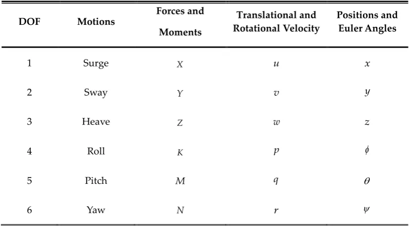
3.2.1 Six Degree of Freedom and Standard Notation ... 30
3.2.2 Coordinate Systems ... 31
vii
3.4 Dynamics ... 34
3.4.1 Equations of Motion for Underwater Vehicle ... 34
3.4.2 External Rigid Body Force ... 36
3.4.3 Determination of the Hydrodynamic Coefficients ... 41
3.5 Summary ... 45
CHAPTER 4 ... 46
Experimental Study of the Conventional Fixed Pitch Propeller ... 46
4.1 Introduction... 48
4.2 Propeller Dynamic Modelling ... 50
4.2.1 The Propeller Open Water Characteristics Curves ... 50
4.2.2 The Propeller Four-quadrant Mathematical Model ... 52
4.2.3 Four-quadrant Model Representations ... 53
4.2.4 The Least Squares Fitting Method ... 55
4.3 Experimental Study ... 56
4.3.1 Open Water Test Setup... 57
4.3.2 Data Acquisition and Post Processing ... 59
4.3 Results and Discussions... 61
4.3.1 Open Water Performance Results ... 61
4.3.1 Four-quadrant Models Results ... 62
viii
Experimental Study of the Collective and Cyclic Pitch Propeller CCPP ... 71
5.1 Introduction... 72
5.2 Experimental Design ... 73
5.2.1 Experimental setup ... 73
5.2.2 Force and moment measurements ... 74
5.2.3 Data acquisition system and signal conditioning ... 76
5.2.4 Experimental program ... 76
5.2.5 Data reduction and representation ... 77
5.2.6 Error analysis ... 78
5.2 Results and Discussions... 79
5.2.1 Bollard pull test ... 79
5.2.2 Captive model test ... 85
5.3 Summary ... 89
CHAPTER 6 ... 90
Manoeuvring Simulation ... 90
6.1 Introduction... 92
6.2 AUVSIPRO – The Simulation Program Description ... 92
6.3 Manoeuvring Design ... 97
6.3.1 Acceleration Manoeuvre Test ... 97
6.3.2 Stopping Test ... 98
ix
6.3.5 Pull-out Manoeuvre ... 100
6.3.6 Zig-Zag Manoeuvre ... 100
6.3.7 Depth-changing manoeuvre ... 101
6.3.8 Meander Manoeuvre ... 102
6.3.9 Spiral Manoeuvre or Helix Manoeuvre ... 103
6.3.10 Reverse Spiral ... 104
6.4 Results and Discussion ... 104
6.4.1 Acceleration Manoeuvre Test ... 104
6.4.2 Stopping Manoeuvre Test ... 109
6.4.3 Static Turning Manoeuvre ... 113
6.4.4 Zigzag Manoeuvre ... 116
6.4.5 Depth-Changing Manoeuvre ... 118
6.5 Summary ... 120
CHAPTER 7 ... 122
CONTROL APPLICATION ... 122
7.1 System Identification ... 125
7.1.1 Introduction... 125
7.1.2 Linear Mathematical Model ... 127
7.1.3 Identification Procedure and Least Squares Method ... 130
7.1.4 Experimental Setup and Data Processing ... 134
x
7.2 Control Application ... 143
7.2.1 Introduction... 143
7.2.2 Control Algorithm ... 144
7.2.3 Simulation Results ... 147
7.3 Summary ... 151
CHAPTER 8 ... 153
CONCLUSIONS AND FUTURE WORK ... 153
8.1 Summary of the Completed Works ... 154
8.2 Main Findings and Conclusions ... 156
8.3 Significance of the Research ... 159
8.4 Future Research ... 160
References ... 164
Appendix A ... 177
xi
LIST OF FIGURES
Chapter 1
Figure 1.1. The cooperation of various systems in the study of marine science. ... 3
Figure 1.2. Remotely Operated Vehicle (left) and Autonomous Underwater Vehicle (right).... 4
Figure 1.3. An AUV in docking mission (left) and an AUV in inspection mission (right). ... 6
Figure 1.4. The Collective and Cyclic Pitch Propeller CCPP. ... 6
Figure 1.5. Gavia class AUV. Courtesy of Teledyne Marine. ... 8
Chapter 2 Figure 2.1. REMUS class AUV. Courtesy of Kongsberg Maritime. ... 15
Figure 2.2. Mares (Cruz and Matos, 2008) and Delphin 2 AUV (Philips et al., 2013). ... 17
Figure 2.3. Slocum glider. Courtesy of Teledyne Marine. ... 18
Figure 2.4. Preswirl Propulsor (Huyer et al., 2012). ... 20
Figure 2.5. AUV water-jet propulsion system (Xin et al., 2013). ... 21
Figure 2.6. The Collective and Cyclic Pitch Propeller CCPP Prototype. ... 23
Figure 2.7. A cross section drawing of the CCPP (Humphrey, 2005). ... 24
Figure 2.8. Collective Pitch Setting of CCPP. ... 25
Figure 2.9. Cyclic Pitch Setting of CCPP. ... 26
Chapter 3 Figure 3.1. Coordinate system... 31
Figure 3.2. Euler’s Angle Transformation. ... 33
Figure 3.3. Two types of the control surface configuration. ... 40
xii
Figure 4.1. Gavia AUV propeller. ... 56
Figure 4.2. Propeller attached into an adaptor... 56
Figure 4.3. The towing tank at AMC-UTAS. ... 58
Figure 4.4. Propeller Open Water Dynamometer. ... 58
Figure 4.5. Internal assembly of Propeller Open Water Dynamometer. ... 59
Figure 4.6. The experimental setup of Propeller Open Water Test. ... 59
Figure 4.7.GaviaAUV propeller open water diagram. ... 62
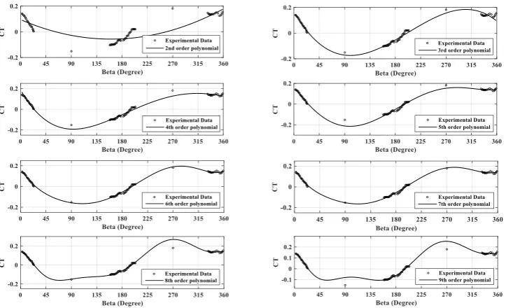
Figure 4.8. Comparison of different polynomial regression models with measured experimental data for thrust coefficient CT. ... 63
Figure 4.9. Comparison of different polynomial regression models with measured experimental data for torque coefficient CQ. ... 63
Figure 4.10. Comparison of different Fourier series regression models with measured experimental data for thrust coefficient CT. ... 66
Figure 4.11. Comparison of different Fourier series regression models with measured experimental data for torque coefficient CQ. ... 67
Chapter 5 Figure 5.1. The experimental apparatus. ... 73
Figure 5.2. The Experimental setup in the Towing Tank... 74
Figure 5.3. The internal and external force balances. ... 75
Figure 5.4. The internal force transducer calibration stand. ... 76
Figure 5.5. Effect of Collective Pitch Angle Settings to KT and KQ. ... 80
Figure 5.6. Effect of horizontal cyclic pitch angle settings. ... 81
Figure 5.7. Effect of Vertical Cyclic Pitch Angle Settings. ... 82
Figure 5.8. Effect of collective and horizontal cyclic pitch angle settings. ... 83
xiii
Figure 5.11. Effect of negative collective pitch angle settings. ... 86
Figure 5.12. Maximum open water efficiency of CCPP in the range of advance coefficient. .. 87
Figure 5.13. Effect of horizontal cyclic pitch angle settings. ... 88
Figure 5.14. Effect of vertical cyclic pitch angle settings... 89
Chapter 6 Figure 6.1. The layout of the AUVSIPRO Simulink Model. ... 94
Figure 6.2. The Signal Builder block as the input signal in the propulsion component. ... 94
Figure 6.3. The Lookup Table block representing the CCPP system mathematical model. .... 95
Figure 6.4. Acceleration Test. ... 97
Figure 6.5. Stopping Test... 98
Figure 6.6. Turning Circle Manoeuvre Test. ... 99
Figure 6.7. Static Turning Manoeuvre Test. ... 100
Figure 6.8. Zig-Zag Manoeuvre Test. ... 101
Figure 6.9. Depth-Changing Manoeuvre Test. ... 102
Figure 6.10. Meander manoeuvre test. ... 102
Figure 6.11. Spiral Manoeuvre Test. ... 103
Figure 6.12. The travel distance of an AUV with FPP in the acceleration simulation test. .... 106
Figure 6.13. The forward speed of an AUV with FPP in the acceleration simulation test. .... 107
Figure 6.14. The travel distance of an AUV with CCPP at 50% collective pitch setting in the acceleration simulation test. ... 107
Figure 6.15. The forward speed of an AUV with CCPP at 50% collective pitch setting in the acceleration simulation test. ... 108
xiv
acceleration simulation test. ... 109
Figure 6.18. The stopping distance versus propeller RPM for the AUV with FPP in the stopping simulation test. ... 111
Figure 6.19. The stopping time versus propeller RPM for the AUV with FPP in the stopping simulation test. ... 111
Figure 6.20. The stopping distance versus cyclic angle for the AUV with CCPP in the stopping simulation test. ... 112
Figure 6.21. The stopping time versus cyclic angle for the AUV with CCPP in the stopping simulation test. ... 112
Figure 6.22. The turning diameter versus deflection angle for the AUV with FPP. ... 113
Figure 6.23. The turning diameter versus cyclic angle for the AUV with CCPP. ... 114
Figure 6.24. Zigzag test of AUV equipped with FPP and CCPP. ... 117
Figure 6.25. The depth change simulation data for the AUV with FPP. ... 119
Figure 6.26. The depth change simulation data for the AUV with CCPP. ... 120
Chapter 7 Figure 7.1. Summary of the proposed identification procedure. ... 131
Figure 7.2. Experimental location. ... 135
Figure 7.3. Gavia AUV performing designed manoeuvrability. ... 135
Figure 7.4. Comparison between the predicted (solid line) and measured (dash lines) angular accelerations for lateral subsystem. ... 137
Figure 7.5. Comparison between the predicted (solid lines) and measured (dash lines) angular accelerations for longitudinal subsystem. ... 137
xv
angular accelerations for the longitudinal subsystem. ... 138
Figure 7.8. Comparison between the simulated (solid lines) and measured (dash lines)
angular velocity yawrate for lateral subsystem. ... 140
Figure 7.9. Comparison between the simulated (solid lines) and measured (dash lines)
angular velocity pitchrate for the longitudinal subsystem ... 140
Figure 7.10. The lawn mower pattern. ... 147
Figure 7.11. Depth control using the LQR. ... 148
Figure 7.12. Pitch angle variation in the depth control. ... 149
Figure 7.13. Input cyclic angle of the CCPP. ... 149
Figure 7.14. Heading control using the LQR. ... 150
xvi
LIST OF TABLES
Chapter 2
Table 2.1. Fundamental specifications of tested propeller. ... 24
Chapter 3
Table 3.1. Standard Notation for Underwater Vehicle Motion. ... 30
Chapter 4
Table 4.1. Definition of four quadrants ... 48
Table 4.2. Fundamental specifications of tested propeller. ... 57
Table 4.3. Towing tank dimensions. ... 57
Table 4.4. The relationship between
and J in the four quadrants. ... 60 Table 4.5. Statistical properties for polynomial regression. ... 65Table 4.6. Statistical properties for Fourier series regression. ... 67
Table 4.7. The Fourier series regression function coefficients. ... 69
Chapter 5
Table 5.1. The force balance axis system. ... 75
Chapter 7
Table 7.1. Assumptions in horizontal and vertical planes. ... 128
xvii
NOMENCLATURE
O
A Frontal area
B Buoyancy Force
CB
Centre of BuoyancyCG
Centre of GravityT
C Thrust coefficient in four-quadrant model
Q
C Torque coefficient in four-quadrant model
d
DiameterF Total force
J Advance coefficient
x
I Mass moment of inertia about the x axis
y
I Mass moment of inertia about the y axis
z
I Mass moment of inertia about the z axis
K Moment about the x axis or rolling moment
T
K Thrust coefficient
Q
K Torque coefficient
l
Length of the vehicleM Moment about the y axis or the pitching moment
m mass of the vehicle
N Moment about the z axis or the yawing moment
n Rotational speed
xviii
Q Torqueq Angular velocity component about the y axis
q Angular acceleration component about the y axis
r Angular velocity component about the z axis
r Angular acceleration component about the z axis
U Total uncertainty in force measurement
t Time value
u Velocity component in direction of x axis (surge)
u Acceleration component in direction of x axis
v Velocity component in direction of y axis (sway)
v Acceleration component in direction of y axis
W
Total weight of AUVw Velocity component in direction of y axis (heave)
w Acceleration component in direction of z axis
X Force in the x axis
x Displacement in the x axis
x Rate of change of displacement in the x axis
B
x The location of CB in x axis
G
x The location of CG in x axis
Y Force in the y axis
y Displacement in the y axis
y Rate of change of displacement in the y axis
B
y The location of CB in y axis
G
y The location of CG in y axis
xix
z Rate of change of displacement in the z axis
B
z The location of CB in z axis
G
z The location of CG in z axis
SSE
Sum of Squares due to ErrorRMSE
Root Mean Squared Error2
R Coefficient of determination
Greek Symbol
Roll angle of the AUV
Roll rate Pitch angle of the AUV
Pitch rate
Yaw angle of the AUV
Yaw rate
Advance angle Control surface deflection angle
col
CCPP collective anglecyc
CCPP cyclic angle
RB
τ External rigid body force
S
τ Hydrostatic force
H
τ Hydrodynamic force
prop
τ Propulsion force
Density of the surrounding fluid
xx
xxi
ABBREVIATIONS
AMC Australian Maritime College
ASV Autonomous Surface Vehicle
AUV Autonomous Underwater Vehicle
CCPP Collective and Cyclic Pitch Propeller
CFD Computational Fluid Dynamic
DAQ Data Acquisition system
DOF Degree of Freedom
EFD Experimental Fluid Dynamic
FPP Fixed Pitch Propeller
IMO International Maritime Organisation
ITTC International Towing Tank Conference
LQR Linear Quadratic Regulator
LS Least Square
PID Proportional-Integrate-Derivative
ROV Remote Operated Vehicle
xxii
UAV Unmanned Aerial VehicleUTAS University of Tasmania
1
CHAPTER 1
Introduction
Chapter 1 provides the context for the thesis, briefly discussing the field of underwater vehicle
propulsion system. The motivation, scope of the research, contribution to research, outline of
2
1.1
Motivation
About 70% of the Earth’s surface is covered with water and its influence is crucial to all aspects.
The past half-century of oceanographic research has demonstrated that the ocean and seafloor
hold the keys to understanding many of the processes responsible for shaping our planet (Steele
et al., 2009). The explorations of marine environment have been providing valuable knowledge
to many fields of science and engineering.
With the assistance of the robotic systems and their advancements, it is possible to reach the
most extreme and remote area on the Earth. Compared to manned underwater vehicles and
human divers, the robotic systems are safer and more efficient. The marine robotics have
expe-rienced tremendous growth for various scientific, civilian and military applications. These
ap-plications include three main categories: inspection and surveying; search and rescue;
surveil-lance and security. Different robotic platforms have been deployed in the study of marine
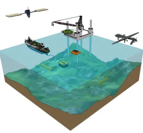
sci-ence and engineering including the Unmanned Aerial Vehicle (UAV), Autonomous Surface
Ves-sel (ASV), and Unmanned Underwater Vehicle (UUV), as shown in Figure 1.1.
Among these robotic systems, UUVs have been the focus for many researchers and are becoming
more attainable for a variety of underwater missions. The UUVs represent a rapid growth with
the potential widespread deployment that will have a significant impact in the future. The recent
development requires the underwater vehicles being capable of accomplishing more complex
and advanced missions in various challenging operational environments; for example, under
ice explorations, deep-ocean floor surveys and industrial subsea infrastructure inspections
(Roberts and Sutton, 2006; Roberts and Sutton, 2012).
Based on the designed tasks and modes of operations the UUVs are categorised as Remotely
Operated Vehicle (ROV) and Autonomous Underwater Vehicle (AUV). The ROVs typically have
3
ship; whereas the AUVs normally have torpedo shape and are able to manoeuvre autonomously
without constant real-time control from operator. AUVs can operate freely with the missions
and control strategy configured in advance. They are widely used in ocean engineering and are
designed to be efficient for the long-range and large-scale survey missions. The application of
AUVs in acquisition of remotely-sensed data includes benthic habitat mapping, marine geology,
fisheries assessment, turbulent water columns and polar region continental shelf mapping
(Lucieer and Forrest, 2016). AUVs may be divided into small AUVs and large AUVs. Small AUVs
may be handled manually and operated from small boats and from shoreline. Large AUVs may
weigh up to several tons and require a research vessel with a dedicated launch and recovery
systems (Ludvigsen and Sørensen, 2016). The application of AUV technology has grown
stead-ily over the last few decades, with particularly rapid growth in the last decade (Nicholson and
[image:32.595.188.471.443.704.2]Healey, 2008).
4
In the AUV development, besides the modern control system design and configuration
modifi-cation, the design of advanced propulsion system is of great interest to facilitate new
applica-tions. The requirements for increased manoeuvrability and functionality have started to pose a
significant impact on the research to improve the current propulsion systems. In this research
context, the propulsion system is considered as the propulsor, which converts the energy from
the power source into the thrust and manoeuvring forces. Depending on the tasks and missions,
different propulsion systems are considered. The torpedo shaped AUV typically consists of the
conventional propulsion system with the main fixed pitch propeller (FPP) providing thrust and
a set of movable control surfaces generating manoeuvring forces. Originally, for this type of
AUV, the main concern with regards to the operation is simply conducing the survey mission.
The conventional propulsion system has been improved to facilitate this traditional mission. The
manoeuvring control accuracy and the optimised efficiency provided by the propulsion system
is essential for the successful completion of an AUV mission. Despite the advantages of FPP,
there are some downsides to their use in AUVs. In recent applications, this type of propulsion
system has been revealing the shortcoming of insufficient low-speed manoeuvrability since
AUV control surface manoeuvring forces are only generated when the vehicle is moving. These
control surfaces are similar to the aircraft’s wings, rudders and elevators, which are effective as
long as they are in motion.
5
It is obvious that the low speed manoeuvring performance is also important in AUV operations,
especially in the docking and intervention missions. For example, the underwater docking for
AUV is preferable since it would be very expensive and time consuming to launch and recover
the AUV on board the mother ship after each mission. Docking has been identified as an
ena-bling capability to support off-board operation of AUVs from submarines, autonomous surface
vessels, other AUVs, ships, and under ice (Bellingham, 2016). The AUV must have the low speed
manoeuvrability to approach the target and connect precisely to the docking platform. In the
intervention application at hovering state, the AUV utilises the robotic arm or the manipulator
for the sample collection in the environment that they are operating. There have been recent
developments and breakthroughs in the underwater manipulator technologies for AUVs (so
called autonomous manipulator) (Kim et al., 2016). The most recent effort is the Trident FP7 EU
research project funded by the European Commission (Kim et al., 2016; Sanz et al., 2012).
Fur-thermore, many underwater applications, such as marine observation and environmental
as-sessment, require stationary observation at low speed. For a number of data collection
opera-tions, it is desirable to be able to deploy an AUV which can travel to a predetermined location,
station itself in the water column at this location while recording environmental data over an
extended time frame and then return to a recovery location (Briggs et al., 2010). In these missions,
the AUV with conventional propulsion is inefficient due to the limitation of the control surfaces
at zero or low speed operation regime. In general, there is limited access to AUVs with station
keeping/hovering capabilities and this is at present the situation for AUVs with manipulator
capabilities doing light intervention and sampling (Ludvigsen and Sørensen, 2016) . The current
desirable characteristics of an AUV platform are cruising at medium to high speed in the survey
missions, station keeping, and manoeuvring at low speed. This thesis has been motivated by the
desire for an alternative propulsion system of a high manoeuvring AUV to be operated not only
6
Figure 1.3. An AUV in docking mission (left) and an AUV in inspection mission (right).
The Collective and Cyclic Pitch Propeller (CCPP) to assist the low-speed operations of an AUV
has been the subject of this research. The key difference between the CCPP and conventional
system is the use of one integrated system instead of the FPP and control surfaces for propulsion
and manoeuvring control. The CCPP has the ability to generate thrust and manoeuvring forces
simultaneously. This feature of CCPP offers the unique and undistinguished capability.
Figure 1.4. The Collective and Cyclic Pitch Propeller CCPP.
The National Centre for Maritime Engineering and Hydrodynamics at Australian Maritime
Col-lege, University of Tasmania (UTAS) has been studying the CCPP system aiming to improve the
7
propulsion systems designed and applied to an AUV. This is in contrast to aerial vehicle such as
helicopter where the use of variable pitch systems is commonplace. Hence, there is an important
need for a research into the viability of this alternative propulsion system and this is the
moti-vation for this thesis.
1.2
Scope of the Thesis
The primary objective of the research project is to investigate the potential of the CCPP as the
propulsion system of choice for a torpedo shaped AUV. In this thesis, the main research question
was that: “Does the AUV equipped with CCPP have better manoeuvrability than the AUV with
FPP”. This thesis looked into the determination of the more applicable propulsion system for
AUVs by numerically comparing the performance of an AUV equipped with CCPP to the
con-ventional FPP. To address the research goal and answer the research question, a methodology
was developed in which both experimental and numerical approaches were utilised.
Experimental approach consisted of the experimental study of the CCPP and FPP in the towing
tank test. The hydrodynamic characteristics of the CCPP were difficult to model by using the
theoretical and numerical approach due to the complexity in working principle. Hence, there
was a need to conduct an experimental study that can measure accurately the generated forces
and to construct the empirical models based on these obtained data. Two types of experiments
were conducted including the bollard pull test and model captive test. The experimental
proce-dure was based on the guideline proposed by the International Towing Tank Conference ITTC.
These model tests have been widely used to predict motions and forces in marine applications.
The CCPP empirical model was made non-dimensional and then scaled to the size of Gavia’s
FPP dimension for the comparison study. Since the CCPP was examined in the low speed
8
the propulsion systems were essential to calculate the AUV’s response to different operational
conditions and control strategies.
The use of CCPP to manoeuvre an AUV represented a challenging problem, which motivated
the need for a simulation. The complexity of manoeuvres in real life makes computer simulation
useful for their study (Lewis, 1988). In this thesis, the numerical approach consisted of
establish-ing the comprehensive mathematical model of the AUV with the hydrodynamic parameters
ob-tained from theoretical and analytical methods; constructing a numerical simulation program
called AUVSIPRO based on MATLAB/SimulinkTM; and developing the control algorithm for
AUV with CCPP. The propulsion system models and hull hydrodynamic model were
incorpo-rated in AUVSIPRO. Although validation is required, the main advantage of this approach is
that it provides a good understanding of the performance of an AUV without the need for the
physical model. In addition, as the development of an AUV is both costly and time consuming,
the use of modelling and simulations is essential to the design process.
Figure 1.5. Gavia class AUV (Courtesy of Teledyne Marine).
At the AMC-UTAS, several AUVs have been used for the research and study. In this project, the
Gavia AUV has been considered as the research platform. The CCPP has been simulated to
em-power the Gavia AUV based on the developed propulsion and vehicle model. Given the Gavia
AUV platform with the conventional FPP propulsion system and the prototype of CCPP, it has
been considered an opportunity to investigate the potential of CCPP for an AUV by conducting
9
1.3
Contribution to Research
The key contributions and achievements of this work are to provide an insight into the
perfor-mance of an AUV equipped with CCPP. There had been insufficient information in the CCPP
hydrodynamic characteristics and the manoeuvrability of an AUV with CCPP had not been fully
examined. The dynamic modelling of an underwater vehicle FPP in four-quadrant operation
was also presented. The in depth comparison results for both propulsion systems CCPP and
FPP provided useful data for the researchers in selecting and designing a propulsion system for
an AUV. The knowledge of the propulsion system characteristics is necessary for the operation
of an AUV. An additional contribution of the research is to develop a controller for an AUV
equipped with CCPP. The control problem of an AUV is very challenging since the
mathemati-cal model of AUV is characterized by high nonlinearity and strongly coupling. The novel
two-stage system identification method was proposed to identify the linear mathematical model of
the Gavia AUV and the optimal linear control algorithm was successfully applied to the system.
1.4
Outline of the Thesis
The thesis documents the experimental and numerical simulation studies conducted in this
re-search project. It is divided into eight chapters as follows:
Chapter 1 provides the context for the following chapters, including the motivation, scope of
the research, outline of the thesis, contribution to research, and the publications.
Chapter 2 describes the background and a comprehensive literature review of the research
pro-ject. It introduces the reasons for interest in alternative propulsion system to the conventional
propeller applied to an AUV. A review of the state of the art of various underwater vehicle
10
are discussed in term of performance characteristics. The chapter also includes a literature
re-view regarding the previous research studies conducted on the CCPP.
Chapter 3 discusses a mathematical model for an AUV. The modelling of an AUV platform is
essential to investigate the manoeuvring characteristics of an AUV equipped with a CCPP. The
reference frames including the earth-fixed and body-fixed coordinates are defined. The
model-ling of an AUV involves the development of both kinematic and dynamic model. The analytical
and theoretical method to estimate the hydrodynamic coefficients are briefly mentioned. This
chapter lay the theoretical foundations of the works conducted in the following chapters.
Chapter 4 and Chapter 5 provide an in-depth modelling of the conventional propulsion system
FPP and the CCPP respectively using the experimental approach. Two separate testing
tech-niques and setups for the FPP and CCPP testing are considered. The experiments to examine
the hydrodynamic characteristics of both propulsion systems are conducted. The obtained data
are analysed and discussed in detail.
Chapter 6 illustrates a detailed manoeuvring simulation of an AUV equipped with FPP and
CCPP. A variety of standard manoeuvring tests for marine vehicles are considered to investigate
the AUV performance.
Chapter 7 examines the control design for an AUV equipped with CCPP. The content of this
chapter includes the two-stage identification method to define the linear model of Gavia AUV
and the optimal control development. The depth and heading control are performed to validate
the controller.
Chapter 8 presents an overview of the works conducted in the research project, summaries the
main findings, emphasises the significance of the study, and provides the suggested direction
11
1.5
Publications
Parts of the thesis have been submitted and published in the following papers in the past three
years during the course of the research project.
1.5.1 Presentations and Conference Papers
Minh Tran, Hung Nguyen, Jonathan Binns, Shuhong Chai and Alex Forrest, A Study of new
propulsion system for an Autonomous Underwater Vehicle, 9th Graduate Research Conference
at the University of Tasmania, Hobart, Australia, 2015.
Minh Tran, Supun A.T. Randeni, Hung D. Nguyen, Jonathan Binns, Shuhong Chai and Alex
Forrest, Least Squares Optimisation Algorithm Based System Identification of an
Autono-mous Underwater Vehicle, Proceedings of the 3rd Vietnam Conference on Control and Automation,
Vietnam, 2015.
Minh Tran, Hung Nguyen, Jonathan Binns, Shuhong Chai and Alex Forrest,AUVSIPRO–A
Simulation Program for Performance Prediction of Autonomous Underwater Vehicle with
Different Propulsion System Configurations. International Conference on Modelling and
Simu-lation for Autonomous Systems. Springer, 72-82.
Minh Tran, Hung Nguyen, Jonathan Binns, Shuhong Chai and Alex Forrest, Optimal control
of an autonomous underwater vehicle equipped with the collective and cyclic pitch
propel-ler. Control Conference (ASCC), 2017 11th Asian. IEEE, 354-359.
1.5.2 Journal Papers
Minh Tran, Hung Nguyen, Jonathan Binns, Shuhong Chai and Alex Forrest, A practical
ap-proach to the dynamics modelling of an underwater vehicle propeller in all four quadrants
of operation, Proceedings of the Institution of Mechanical Engineers, Part M: Journal of
12
Minh Tran, Hung Nguyen, Jonathan Binns, Shuhong Chai and Alex Forrest, Experimental
Study of the Collective and Cyclic Pitch Propeller, The Journal of Marine Science and
Applica-tion. (Accepted for publication).
Minh Tran, Hung Nguyen, Jonathan Binns, Shuhong Chai and Alex Forrest, A comparison
study of two propulsion system configurations for an autonomous underwater vehicle,
13
CHAPTER 2
Literature Review
This chapter describes the background and literature review of the research project. It introduces
the reasons for interest in an alternative propulsion system to the conventional propeller applied
to an AUV. In this chapter, a review of the state of the art of various underwater vehicle
propul-sion systems are presented. The advantages and disadvantages of these propulpropul-sion systems are
discussed in term of performance characteristics. The chapter concludes with the literature
re-view of previous research conducted for CCPP propulsion system.
Part of this chapter has been published in the “Proceeding of 9th Graduate Research Conference at the
University of Tasmania”. The citation for the presentation is:
Minh Tran, Hung Nguyen, Jonathan Binns, Shuhong Chai and Alex Forrest, A Study of new
propulsion system for an Autonomous Underwater Vehicle, 9th Graduate Research Conference at
14
2.1
Introduction
AUVs play a critical role in the maritime industry to provide automated missions. AUV
tech-nology is a fast growing research area with a wide range of subsystems being developed. One
of the key challenges each AUV experience, is achieving an accurate manoeuvrability.
Essen-tially, a basic consideration for the design of swimming machines is the design of propulsors:
their shape, location on the robot, mechanical properties (e.g., inertia and stiffness), and pattern
of movement (Colgate and Lynch, 2004). In this chapter, the conventional propulsion system for
a torpedo shaped underwater vehicle and its performance characteristics are presented. In
ad-dition, a comprehensive literature study is mentioned to describe the relevant propulsion
sys-tems with different configurations as alternative propulsion system to the conventional one. A
brief description and performance analysis of these propulsion systems are conducted,
discuss-ing the advantages and disadvantages of usdiscuss-ing these systems. Finally, the CCPP configuration
is briefly explained and the previous works related to the research of CCPP is reviewed.
2.2
Conventional propulsion system for an autonomous underwater vehicle
and its limitations
2.2.1 Conventional propulsion system with Fixed Pitch Propeller (FPP)
In modern subsea mapping and surveying applications, AUVs are usually designed for high
speed cruising so that the vehicles are able to cover the longer distance and larger range of
in-spection area from several meters to hundreds of meters. A majority of work related to
propul-sion system has been conducted on the traditional propeller-driven propulpropul-sion.
The use of a FPP at the aft end combined with control surfaces as means of propulsion are
prev-alent for underwater vehicles, especially for torpedo-shaped AUVs, such as HUGIN 1000 class
15
this conventional configuration, the FPP provides thrust for AUV while the manoeuvring of an
AUV is achieved through adjustment of the control surfaces. Additionally, the ducted propellers
are also utilised to increase the propulsion system efficiency of AUVs, including AUV PreToS
(Chakrabarti et al., 2014) and Gavia class (Hiller et al., 2012).
Figure 2.1. REMUS class AUV. (Courtesy of Kongsberg Maritime).
2.2.2 Limitations of the conventional propulsion system
It is essential that the control surfaces be capable of generating manoeuvring forces that are
sufficient in magnitude and oriented in desired control directions. However, these traditional
types of propulsion system have the shortcoming of insufficient low-speed manoeuvrability
be-cause low aspect ratio control surface characteristics significantly limit their effectiveness
(Huyer et al., 2010; Farnsworth et al., 2010). With the exception of thrust from the propeller,
AUV control surface manoeuvring forces are only generated when the vehicle is in motion at
sufficient speed. Hence, the AUV missions at zero and low speed are limited.
The control surfaces and other appendages protruding from the hull can be damaged when the
vehicle travelling in a confined environment. They are also easily to be affected by the
environ-mental disturbances and turbulence. In such a condition, the control surfaces are not able to
produce enough forces and moments to counteract the influences resulted from strong ocean
currents. In term of efficiency, the lack of variable pitch capability of the conventional propeller
leads to AUV propulsion having relatively low efficiency at different operational conditions. For
16
AUV, which could increase the functionality and manoeuvrability at different operational
speeds and missions. The aim of the next generation of AUVs is also to be able to combine long
range survey capabilities with low speed investigation of the environment encountered (Palmer,
2009). For example, with the growing acceptance of survey-class AUVs in the commercial sector,
interest is growing in the use of AUVs for activities such as periodic inspection of subsea
equip-ment installations and the use of AUVs for maintenance and repair activities (Bellingham, 2016).
In addition, the underwater docking represent a major challenge in the design and improvement
of current AUV propulsion.
2.3
Alternative Propulsion Systems for an Underwater Vehicle
There are already various concepts of propulsion systems, which have been designed and
ap-plied to an underwater vehicle as the solution to the downsides of a conventional FPP. These
following sections describe some of the prevalent types with their specific mechanisms and
unique performance capabilities. The purpose is to give an overview of the current state of
re-search in the fields related to underwater vehicle propulsion system.
2.3.1 Thruster
To enhance the low speed manoeuvrability, the thrusters are utilised and positioned at different
locations around the AUV without changing the low drag profile of the torpedo-shaped AUV.
The thrusters are categorised into two main different types: through-body thrusters (tunnel
thrusters) and the external thrusters. Adding thrusters enables the vehicle to travel long
dis-tances at high speeds to a desired destination and then perform tasks that require low speed
manoeuvrability (Saunders and Nahon, 2002). Thruster is the standard choice in propelling low
speed AUV and is widely used in turbulent environment since its generated forces and moments
are generally independent of surrounding fluid. A number of these AUVs have been developed,
17
Nahon, 2002), Odyssey (Eskesen et al., 2009), and Mares (Cruz and Matos, 2008). The propeller
based thrusters have been employed for low speed control due to their reliability,
responsive-ness and ability to generate forces throughout the operational range of the vehicle (Palmer, 2009).
Figure 2.2. Mares (Cruz and Matos, 2008) and Delphin 2 AUV (Philips et al., 2013).
However, the disadvantage of using thrusters is the reduced propulsive efficiency at high speeds.
Tunnel thrusters could increase the parasitic drag of the vehicle and also take up considerable
volume that could otherwise be used for energy or payload (Huyer et al., 2010). Hence, the
in-ternal architecture of the AUV using tunnel thrusters are quite complex. Moreover, the exin-ternal
thrusters are vulnerable to the damage and corrosion since they are subject to high influx of
water. A number of thrusters installed in close proximity result in the cross-coupling
interac-tions influencing the control characteristics considerably (Russell and Bellec, 1981).
2.3.2 Vectored Thruster
An alternative to the conventional propeller that could improve the manoeuvrability and
effi-ciency of underwater vehicles is the vectored thruster propeller, or a steerable propeller. The
vectored thrusters are a special type of the thrusters. The vectored thruster propellers applied
to underwater vehicle are inspired from the azimuthing podded propulsion system for ships
con-18
trolled by actively altering the thruster direction. In spite of the mechanical complexity, the
ad-vantages of using vectored thruster propeller for propulsion system of AUV include improved
manoeuvrability, and the fact that fewer fins, which may snag on underwater cables or other
obstacles in a confined environment, protrude from the vehicle (von Ellenrieder and Ackermann,
2006). The vectored thruster propulsion for underwater vehicle is still under development and
has not been applied in practical application.
2.3.3 Buoyancy Engine
To increase the hover capability of the conventional torpedo shaped AUV, researchers have
come up with some modifications to the propulsion system by taking advantage of the balance
between buoyancy and hydrodynamic forces by changing the ballast mass to drive it in water
(Abraham and Yi, 2015). A review for popular buoyance engines which mainly used for the
underwater gliders could be found in reference (Ullah et al., 2015). Autonomous large area
sur-veys of ocean are currently carried out using either flight-style propeller-driven AUVs or gliders
(Furlong et al., 2007). The endurance of glider is significantly longer than the traditional AUV.
The power requirement for gliders are substantially low in the comparison to the
propeller-driven AUVs. A detailed discussion on the current studies of the gliders could be found in the
following reference (Jenkins and D’Spain, 2016).
19
The glider is an effective tool in measuring water column parameters. However, the accuracy in
navigation and manoeuvring is limited (Ludvigsen and Sørensen, 2016). The produced thrust
from buoyancy engine is not sufficient compared to other types of propulsion system resulting
in the gliders instability to environmental disturbances. Hence, the gliders are not able to
oper-ate in the strong ocean currents. Moreover, due to the nature of their propulsion system gliders
are restricted to seesaw flight profiles (Furlong et al., 2007).
2.3.4 Biomimetic propulsion
Researchers also look to nature as an inspiration for their design where the biomimetic
propul-sion system has been considered (Mazlan and Naddi, 2015). Nature preserve various means of
underwater propulsion. Different species display a multitude of propulsion and manoeuvring
methods appropriate for their environment (Riggs, 2010). Research on aquatic animals has
in-creased and these animals have been mimicked to improve underwater vehicles and their
loco-motion mechanisms for better performance (Korkmaz et al., 2015). The most popular types of
biomimetic propulsion system are the flapping foil (flexible fins) and the oscillating paddle
(rigid paddles). Creatures with the large ratio of body weight to surface are normally propel
themselves by flapping their wings continuously while natural species with the small ratio of
body weight to area swim propelled by transferring momentum to water with the mechanism
similar to jet propulsion. The swimming animals share some of similar mechanisms with flying
animals but the fundamental nature of generated thrust is different. The primary goal in flying
is the continuous production of steady lift, to balance the large body weight within a medium
with small density. The major goal in fish swimming is to minimize drag forces within a medium
a thousand times more dense than air—the generation of steady lift to support the (small) net
weight is of secondary or no importance at all (Triantafyllou et al., 2004). The biomimetic
20
propeller and other rotating propulsions. Biomimetic propulsion also offers some distinct
ad-vantages such as excellent manoeuvrability for steering and low-noise operation, but is
consid-ered not propulsive efficiency (Korde, 2004). Although there exist solutions on the efficiency
issues, there are many challenges to overcome related to the mechanical design. The mechanism
of current biomimetic propulsions are still complex and hard to control. Considerable efforts
have been put into the investigation of biomimetic propulsion to decrease its power
consump-tion and increase funcconsump-tionality (Read, 2001; Watts, 2009; Roper et al., 2011; Polidoro, 2003;
Hubbard et al., 2014). Solving these issues will greatly facilitate the development of underwater
marine robotics.
2.3.5 Preswirl Propulsor
Another concept of underwater propulsion is the preswirl propulsor. This propulsor has been
designed with the intention to overcome the limitation of the conventional FPP. This novel
pro-pulsor utilises an upstream stator row, where the individual stator blade pitch angles can be
varied, coupled with a downstream rotor. By sinusoidally varying the individual stator blade
pitch angles around the circumference, the upstream stator row produces a significant side force
(Huyer et al., 2012; Huyer et al., 2010; Farnsworth et al., 2010). The prototype of preswirl
pro-pulsor has been successfully tested but its application to an AUV has not been reported.
21
2.3.6 Jet-pump or waterjet PropulsionIn the jet-pump or waterjet propulsion, the water is absorbed into the water hydraulic pump
from the bow section of the AUV. After being pressurised, the water jets out of the nozzle and
generates reaction thrust (Xin et al., 2013). The yaw and pitch manoeuvres are performed by
either the differential thrust mechanism or the waterjet steering system.
Using jet-pumps for propulsion and steering is an alternative option to the conventional
propel-ler-driven propulsion. Pump and jet systems are less energy efficient with respect to blade
pro-pellers and rudder steering (Alam et al., 2014). The jet-pump also offers several advantages from
the point of view of the mechanical design (absence of rotating parts and transmission
mecha-nisms), realization cost (simpler fibre-class cover), robustness with respect to
transportation/de-ployment/recovery damages (no appendixes protruding from the cylinder), safety of occasional
swimmers in proximity of the vehicle (jet-pumps are much less likely to cause harm at low speed
with respect to propeller blades) (Alvarez et al., 2009). The investigations and studies of
jet-pump propulsion for AUVs have been examined thoroughly in the literature (Korde, 2004;
Polsenberg Thomas, 2007; Mohseni, 2006). However, the waterjet propulsion are generally not
used for medium-speed and high speed applications due to the decrease in efficiency. The
con-trol accuracy of waterjet propulsion is limited in the underwater environment in which the six
[image:50.595.266.394.595.723.2]degree-of-freedom manoeuvrability is required.
22
2.3.7 Hybrid PropulsorsThere are a number of AUVs integrating different methods of locomotion in one system. The
hybrid propulsion system have been extensively studied as a potential means for improvement
of underwater vehicle performance. An excellent example of this can be seen on the Tethys-class
AUV built by the Monterey Bay Aquarium Research Institute. The Tethys-class AUV has a
unique ability to operate efficiently in three different operational modes with a range of
actua-tors: traditional propeller for high speed, a moving internal mass (like a glider) for low speed,
and variable buoyancy for drifting (like a float) (Hobson et al., 2012). The Guanay-II AUV uses
the propulsion system comprises: a main engine, which provides the propulsion, two side
thrusters, which monitor the direction of the vehicle and an internal pneumatic stainless
cylin-der, which allows the vehicle to dive by taking in and ejecting water (Gomáriz et al., 2015).
An-other hybrid AUV uses ducted propeller and rudder located at the aft for horizontal motion and
internal mass shifter mechanism for vertical motion (Tran et al., 2015b) or the internal rolling
mass mechanism for roll control (Hong and Chitre, 2015). The internal actuators are located
inside the vehicle hull and hence are less subject to damage than the external thrusters are.
How-ever, the use of moving internal actuators are limited due to the significant requirement for the
inner hull space and high power consumption from multiple systems. Additionally, it is
chal-lenging to design the control strategy for the integrated propulsion unit with different force
generation methods.
2.4
Collective and Cyclic Pitch Propeller (CCPP)
Even though a variety of improvements and innovations has been made, the development of an
advanced propulsion system for an AUV remains a challenging research area. It is essential to
develop the alternative means of propulsion system for AUVs that could increase both efficiency
23
the current propulsion configurations and to investigate its performance characteristics in
un-derwater working environment. The most attractive characteristic of CCPP is its capability to
generate continuous thrust and manoeuvring forces simultaneously. The CCPP propulsion
sys-tem has improved the underwater vehicle efficiency at cruising speed and the high degree of
manoeuvrability at low speed without using the control surfaces. This section explains its basic
configuration and reviews the development of the CCPP.
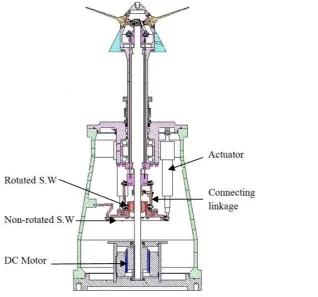
The CCPP, as shown in Figure 2.6, has the similar working principle to the conventional main
rotor of the helicopter (Seddon and Newman, 2011) and the variable vector propeller of an
un-derwater vehicle (Nagashima et al., 2006). The essential component of CCPP is a swashplate,
which is controlled by linear actuators, as shown in Figure 2.7. The swashplate enables the
ad-justment of the propeller pitch angles as the shaft is rotating. There are two primary blade
[image:52.595.132.523.424.697.2]set-tings in the CCPP configuration, the collective pitch setting and the cyclic pitch setting.
24
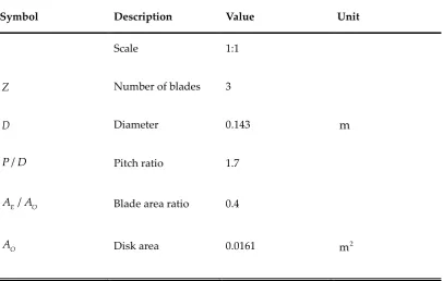
[image:53.595.119.540.160.377.2]The main particulars of the examined model are given in Table 2.1.
Table 2.1. Fundamental specifications of tested propeller (Humphrey, 2005).
Symbol Description Value Unit
Scale 1:1
Z Number of blades 4
Blade section NACA 0012
D Diameter 0.305 m
col
Collective angle -29 to 29 Degree
cyc
[image:53.595.197.516.416.713.2] Cyclic angle -20 to 20 Degree
25
The collective pitch setting of the CCPP is similar to Controllable Pitch Propeller (CPP) which is
well-known for the advantage of full power utilisation at any circumstances, such as:
accelerat-ing and stoppaccelerat-ing; rapid manoeuvraccelerat-ing; and dynamic positionaccelerat-ing (Dang et al., 2012). The pitch
angles of all blades could be changed simultaneously to a particular value at position 1, 2, 3 and
4 in the collective pitch setting. As shown in Figure 2.8, all the blades are increased to a defined
value. This feature allows the propulsor to alter its axial thrust without changing the propeller
rotational speed. The CPP has been studied for an AUV specially designed in the tunnel
inspec-tion mission (Jung et al., 2012). In these types of mission, the reverse thrust is crucial as the
vehicle is operating is narrow space. In addition, the ability to change the pitch angle results in
the optimised thrust from CCPP at various operating speeds. This helps the AUV reach
maxi-mum efficiency in different operations, avoid the motor to be overloaded and increase the motor
duration (Tarbiat et al., 2014).
Figure 2.8. Collective Pitch Setting of CCPP.
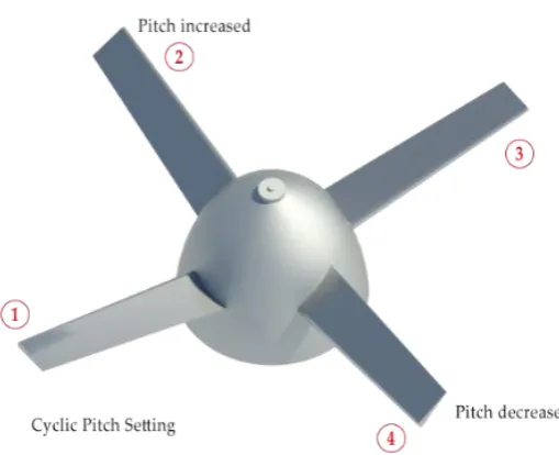
CCPP is primarily different from the CPP in the cyclic pitch control to create the manoeuvring
26
surface but due to the cyclic pitch setting. The angles of each propeller blade can also be
posi-tioned periodically during a rotation in the cyclic pitch setting by manipulating the orientation
of swash plate. As shown in Figure 2.9, the blade pitch angle will be increased in position 2,
decreased in position 4; and remained neutral in position 1 and position 3 per revolution. As the
results, more lift will be created in position 2 and the side force as well as the moment are created.
Therefore, the CCPP can generate thrust, as well as manoeuvring forces and moments in
differ-ent directions. The physical parameter and dynamic model of CCPP will be presdiffer-ented
[image:55.595.214.469.321.528.2]thor-oughly in the next chapters.
Figure 2.9. Cyclic Pitch Setting of CCPP.
Extensive research has been conducted in the aeronautics on the helicopter main rotor. However,
there has been limited publications in the literature considering the unique features of CCPP
and its applications to marine underwater vehicles. The complex mechanical design and control
system associated with this propulsion system has prevented the extensive research effort.
27
of CCPP utilised in this study was initially built at Memorial University of Newfoundland,
Can-ada (Humphrey, 2005). A prototype CCPP with control system was designed, constructed and
tested. A series of initial tests were carried out to study its characteristics in the open water
con-dition. The most recent research was conducted at the Australian Maritime College, University
of Tasmania to investigate the performance of an underwater vehicle model equipped with
CCPP in straight line model captive test (Niyomka, 2014). In addition, the prediction program
for performance of CCPP was also constructed using BEMT and the Leishman-Beddoes
dy-namic stall model. Although the innovative features of CCPP for underwater vehicle were
dis-covered from previous studies its performance characteristics were not fully demonstrated yet.
Additionally, due to the lack of experimental data, the modelling and simulation studies were
not conducted in detail. Therefore, the potential application of CCPP to an AUV has not been
verified. In response to the shortcomings of previous works, the studies with underwater
vehi-cle model equipped with CCPP have been carried out thoroughly in this thesis. The analytical
method, experimental approach and numerical simulation are presented and applied in the next
chapters. The methodologies associated with these approaches are also reviewed and explained.
2.5
Summary
The background and literature review of the research project were described in chapter 2. It
introduced the reasons for interest in alternative propulsion system to the conventional
propel-ler applied to an AUV. It also presented a review of the state of the art of various underwater
vehicle propulsion systems, and more specifically, the propulsion system for the torpedo shaped
underwater vehicle. The advantages and disadvantages of these propulsion systems were
dis-cussed thoroughly in term of mechanisms and performance characteristics. Chapter 2 concluded
with a literature review of previous research conducted for the CCPP to pave way for the current
28
CHAPTER 3
AUV Equations of Motion
This chapter discusses the mathematical model of an underwater vehicle. The modelling of an
AUV involves the development of both kinematic and dynamic model. The analytical and
the-oretical method to estimate the hydrodynamic coefficients are briefly presented. This chapter
provides the theoretical foundations for the further investigation conducted in the following