AN IMPLEMENTATION OF X.25 OVER TCP/IP
A Thesis Presented in Partial Fulfilment
of the Requirements for the Degree of
Master of Technology in Computing Technology
at Massey University
Ajitkumar J. W. Rasiah
ACKNOWLEDGMENTS
I am indebted to my supervisor, Dr. Peter Kay of the Department of Computer Science, Massey University, for his invaluable advice, assistance and helpful criticism throughout this study and the preparation of this manuscript. His patience and encouragement are greatly appreciated.
I also wish to thank:
Professor Robert M. Hodgson of the Department of Production Technology, Massey University, for providing the opportunity for this study.
Professor Mark D. Apperley of the Department of Computer Science, Massey University, and the Massey University Computer Centre for providing the facilities for this study.
CONTENTS
ACKNOWLEDGMENTS ... ii
CONTENTS ... iii
LIST OF FIGURES ... vii
ABSTRACT ... viii
1. INTRODUCTION ... ! ,1.1 The Rapid Growth of Computer Networks ... ! 1.2 International Standards Organizations ... 2
1.3 Protocols ... 2
1.4 Reference Models ... 3
1.5 Objectives of the Project ... 7
2. CCITT X.25 RECOMMENDATIONS ... 9
2.1 Packet Switching Data Networks ... 9
2.2 CCITT X.25 Recommendations ... IO 2.3 The Structure of X.25 ... 11
2.4 Virtual Calls ... 12
2.5 X.25 Packet Formats ... 12
2.5.1 Call Set-up and Clearing Packets ... 13
2.5.2 Data and Interrupt Packets ... 14
2.5.3 Resetting and Restarting Packets ... 14
2.6 Flow Control ... 16
2.7 Packet Assembly/Disassembly Devices ... 17
2.8 Efficiency Considerations ... 17
3. THE INTERNET PROTOCOL SUITE ... 19
3.1 Background ... 19
3.2 Layering in the Internet ... 20
3.3 Internet Addressing ... 21
3.4 The Transmission Control Protocol (TCP) ... .22
3.5 The Internet Protocol (IP) ... 24
4. UNDERLYING NETWORK SERVICES ... 26
4.1 Link Access Protocol B (LAPB) ... 26
4.1.1 LAPB Frame Format ... 26
4.1.2 LAPB Frame Types ... 27
Information Frames ... 27
Supervisory Frames ... 28
Unnumbered Frames ... 28
4.2 Bus Networks ... 30
4.3 IEEE 802 ... 32
4.3.1 IEEE 802.2 (LLC) ... 32
4.3.2 IEEE 802.3 (CSMA/CD) ... 35
Ethernet ... 35
4.4 IP over Ethernet ... 37
4.4.1 Address Resolution Protocol ... 37
4.4.2 Ethernet Frame Contents for IP ... 37
4.4.3 TCP Maximum Segment Size Option ... 38
4.4.4 Datagram Fragmentation ... 38
4.5 X.25 over CSMA/CD ... 40
4.5.1 Data Link Layer Management ... .40
4.5.2 Layer Management ... 42
4.6 Serial Line IP (SLIP) ... 44
4.6.1 SLIP Protocol Description ... .44
4.6.2 Deficiencies ... 44
4.7 Point-to-Point Protocol (PPP) ... .46
4. 7 .1 PPP Layering ... 46
The Physical Layer ... 46
The Data Link Layer ... 47
4.7.2 Link Control Protocol (LCP) ... .48
LCP Packets ... 48
LCP Actions and Events ... 49
LCP Configuration Options ... 51
4. 7 .3
IP Control Protocol (IPCP) ... 524.8 ISO Development Environment (ISODE) ... 53
4.8.1 ISODE Communities ... 53
4.8.2 Transport Service Bridges ... 54
4.9 VMS Packet Switch Interface (PSI) ... 58
4.10 IP over X.25 ... 58
5. IMPLEMENTATION OF X.25 OVER TCP/IP ... 61
5.1 Introduction ... 61
5.2 The Client-Server Model of Interaction ... 62
5 .3 Overview of the Implementation ... 63
5.4 The X.25 Library ... 65
5.4.1 Modes of Operation ... 66
5.4.2 Buffering ... 66
5.4.3 Handling Special Packets ... 66
5 .5 The X.25 Library Interface ... 68
5.5.1 socket() ... 68
5.5.2 connect() ... 69
5.5.3 bind() ... 71
5.5.4 listen() ... 72
5.5.5 accept() ... 72
5.5.6 write() ... 73
5.5.7 read() ... 74
5.5.8 select() ... 75
5.5.9 ioctl() ... 76
5.5.10 close() ... 77
5.5.11 perror() ... 78
5.6 The Pyramid Server ... 79
5.6.1 Servicing Clients ... 79
5.6.2 Managing an X.25 virtual call ... 82
5.7 The Incoming Call Server (ICS) ... 84
5.7.1 Operating as a client program ... 84
5.7.2 Operating as a server program ... 85
5.8 Code Examples ... 86
5.8.1 Example 1 - Simple Packet Assembler/Disassembler (Spad) ... 86
Spad Commands ... 86
X.3 Facilities provided by Spad ... 88
Spad Listing ... 91
5.8.2 Example 2 - Caser ... 113
5.8.3 Example 3 - Echoer ... 118
6. FUTURE DEVELOPMENTS AND CONCLUSIONS ... 129
6.1 Addition of X.25 Facilities ... 129
6.2 Possible Improvements to Spad ... 134
6.3 Conclusion ... 135
LIST OF FIGURES
Figure 1.1 - The OSI Reference Model ... .4
Figure 1.2 -The TCP/IP Internet Layering Model.. ... 6
Figure 2.1 -Topology of a Packet Switching Data Network ... 10
Figure 2.2 -I-ID LC Frame Structure ... 11
Figure 2.3 - Main X.25 Packet Formats ... 13
Figure 3 .1 - Layering in TCP /IP using a router ... 20
Figure 3.2 - TCP Packet Fonnat. ... 23
Figure 3.3 - IP Datagram Fonnat ... 24
Figure 4.1 - Control field of a LABP frame ... 27
Figure 4.2 - Bus network Topology ... 31
Figure 4.3 - The IEEE 802 LLC Frame Format ... 34
Figure 4.4 - Ethernet Frame Fonnat. ... 36
Figure 4.5 - Standard PPP frame structure ... .47
Figure 4.6 - ISODE Bridge ... 55
Figure 4.7 -TP0 Addressing Formats ... 56
Figure 4.8 - Topology of VMS PSI Data Link Mapping ... 58
Figure 4.9 - Transport Service Bridge ... 59
Figure 5.1 - The Client-Server model.. ... 62
Figure 5.2 - Outgoing call example ... 64
Figure 5.3 - Incoming call example ... 65
ABSTRACT
Computer Networks are being used increasingly around the world. More importantly, many of these networks are interconnected by gateways, allowing a user in one geographical location to send and receive messages from a host located elsewhere.
The International Standards Organisation (ISO) has proposed the Open Systems Interconnection (OSI) Reference Model as a basis for building computer networks and the protocols which are used on those networks. Developers of networks are encouraged to follow these guidelines so that their networks may have an 'open architecture'.
CHAPTER 1
INTRODUCTION
1.1 The Rapid Growth of Computer Networks
Computer networking is an area of technology which has rapidly grown over the past decade. A few years ago networks were research tools used by a few specialist organizations. Over the period of a few years computer networks gained a reputation for usefulness and reliability and many more organizations recognized the necessity to invest in a public or private network of some kind for daily use with machines ranging from personal computers to supercomputers. A computer network offers a practical means of communication and eliminates the problem of isolation which many organizations have previously experienced. Organizations have come to rely on computer networking to an extent that they are almost helpless without one. World-wide electronic mail is used daily by millions of people. Over the past decade networks have evolved from being a research tool used by academics to an essential tool for users in business, government and research institutions.
As networking evolved, every computer manufacturer had a different networking architecture that was incompatible with the products of other manufacturers. This is now changing. Almost the entire computing industry has agreed on standardizing the architecture of networks. The spin-offs from the resulting standards are already apparent. The products of one manufacturer can communicate easily with the products of other manufacturers.
The advantages of using computer networks are immense. One of the most significant is resource sharing. This enables a community of users in one geographical location to share resources with another community somewhere else. Most universities and research institutions nowadays make their computing facilities available to remote users via resource sharing networks. This means that a lecturer or student at one university can employ the facilities at any other university on the network.
large number of computer solutions for engineering design or evaluation. These are made available to engineers throughout the corporation via a corporate network.
1.2 International Standards Organizations
Computer networks may be found in most countries today. The equipment and protocols that are used is varied and so it is necessary to define standards for obtaining maximum compatibility. The ISO, CCITT and IEEE organizations make major contributions towards standards in many areas.
The International Organization for Standardization (ISO) is a body which produces recommendations of all types. It has a computer technical committee which is responsible for all types of computer standards. One of its most important achievements is the Open Systems Interconnection (OSI) reference model.
The International Telegraph and Telephone Consultative Committee (CCITT) is a United Nations committee which makes recommendations about telephone and data communications services. The recommendations are revised every four years. Many of the CCITT's recommendations have been adopted to an extent that they have become the standard. X.25 is one such example.
The Institute of Electrical and Electronics Engineers (IEEE) is a large, professional organization which has comprises of a number of smaller interest groups to which members can belong. One of these groups deal with standardization and develop standards in the electrical engineering and computing areas. IEEE's 802 standard for local-area networks is widely used and has subsequently been taken over by ISO as the basis for ISO 8802.
1.3 Protocols
Many different protocols exist for use over computer networks. A protocol may be used on its own or as part of a 'layer' or hierarchy of different protocols which collectively make up a networking system. Two of the most well-known protocols used today are X.25 and TCP/IP.
1.4 Reference Models
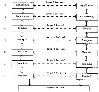
To reduce the complexity in network design, most networks are organized as a hierarchy of levels or layers. This approach was conceived when it was realized that the functions required for data communications are best implemented in a hierarchical fashion. The purpose of each layer is to offer certain services to the layers above whilst shielding them from the details of how the services are actually implemented. A layer on one machine communicates with the corresponding layer on another machine using a protocol suitable for servicing that layer. In this instance, the protocol will not be suitable for use with other layers. The set of layers and protocols is called the network architecture. The network architecture is based on an abstraction called the Reference Model.
Appli,:ation. I.ayer 7 Protocol
I.ayer 7
-
- - -
-
-
Appli,:ation.I.ayer 6 Protocol
6 Prue:nhtion.
- - -
- -
Prue:nhtion.I.ayer 5 Protcol
5 Su1ion.
- - - - -
Su1ion.I.ayer 4 Protocol
4 Toll.5 p O l't
- -
- - -
Toll.5portI.ayer 3 Protocol
3 Network
-
- -
- -
NetworkI.ayer 2 Protocol
2 Data I.ink
- -
-
- -
Data I.inkI.ayer 1 Protocol
[image:13.597.126.461.77.389.2]1 Ph.~:bl
- -
- -
-
Ph.~icalFigure 1.1 - The OSI Reference Model
Layer 1, called the physical layer, is responsible for transferring raw bits from one end of a communication channel to the other. The design issues in this layer are mainly concerned with the mechanical and electrical interfaces to the network and the physical transmission medium.
The data link layer (layer 2) is responsible for taking the raw transmission facility and transforming it into a line that appears free of transmission errors. This is done by breaking down the data that is passed to it by layer 3 above into data frames, typically containing a few hundred octets, and adding error checking information. Layer 2 then passes them to layer 1 which transmit the frames sequentially. The receiver typically uses the error checking information to check that the frame has not been corrupted during transit by noise on the line. It then sends back an acknowledgement frame to the sender, or requests the sender to retransmit the frame if data corruption has occurred.
communicate packets of data between different hosts on the network. Layer 3 must also control the maximum number of packets in the network at any time. If too many are in transit, the network will become congested and it's performance will degrade.
The transport layer (layer 4) is responsible for accepting data from the session layer, splitting it up into smaller pieces if necessary, passing these to the network layer, and ensuring that the pieces all arrive correctly at the other end. All this must be done efficiently, and in a way which makes the session layer independent of changes in the hardware technology. The transport layer must create network connections as required by the session layer. If the session layer requires a high throughput then the transport layer may create multiple network connections and divide up the data among the network connections to improve throughput. Alternatively, the transport layer may multiplex several transport connections onto a single network connection if creating and maintaining a network connection is expensive. The transport layer also determines the type of service to provide the session layer, such as message broadcasting to multiple destinations, message transmission with no guarantee of the order of delivery, or an error-free point-to-point channel which delivers messages in the order in which they were sent. Transport layer protocols have end-to-end (host-to-host) significance, meaning that this layer and the layers above it are implemented on the host, rather than in the network. The transport layer also provides packet resequencing and flow control to ensure that data arrives safely at the destination.
Layer 5, the session layer, allows users on different machines to establish sessions (connections) between them by providing procedures for initializing, controlling the dialogue and terminating the sessions. A session might, for example involve a user logging onto a time-sharing remote host to use a facility that it offers. One of the services that the session layer provides is dialog control, where it must determine whether the message traffic is exchanged in a full-duplex or a half-duplex fashion. Another essential session service is synchronization. If a large file transfer crashes, then retransmitting the entire file can be avoided since the session layer is able to provide checkpoints into the data stream and therefore only the data after the last checkpoint must be repeated.
provide error-free data transmission. This way, the presentation layer is free to concentrate on the syntax and the semantics of the data
Layer 7, the application layer, is the highest of the seven layers. This provides a means by which application programs can gain access to the OSI environment for the purpose of exchanging information with application programs on remote hosts.
The network layer and below are largely used by the CCITT X.25 definition. However there have been some alterations at layer 3 since the existing X.25 definition was not completely satisfactory for direct use in the OSI environment.
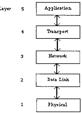
Variations of the OSI reference model exist under different names. One widely used variation is the TCP/IP Internet Layering model where applications reside directly above the transport layer and have application-specific session and presentation layers. This model forms the basis of the TCP/IP protocol suite.
I.11y«r 5 A.pplic11tion.
4 Tu:n.sp Ort
3 Network:
2 Dlltll I.in.k
[image:15.597.215.351.355.543.2]1
1.5 Objectives of the Project
This thesis examines two widely used networking protocols, X.25 and TCP/IP. It covers much of the details pertaining to layers 1 to 3 of their architecture. It then describes the design and implementation of software for running X.25 over TCP/IP.
The implementation of X.25 over TCP/IP was stimulated by the networking requirements of the Department of Computer Science at Massey University. The department runs two Ethernet local-area networks which are used to connect a wide variety of devices. These devices include Sun workstations, Apple Macintosh and IBM Personal Computers, and a laser printer. TCP/IP is run over the Ethernet which allows an already extensive networking environment to grow even further. However, the computing facilities at the department do not include a connection to a public data network. Therefore software development in the networking area is restricted to the TCP/IP environment.
The Massey University Computer Center runs a Pyramid minicomputer, which is also connected to the Internet. However, this machine has the added feature that it is connected to a public data network. This provided the motivation to develop software that would allow users at the Department of Computer Science to write local X.25 software, use TCP/IP to reach the Pyramid, and use the Pyramid's connection to the public data network.
The implementation was developed in 'C' under the UNIX operating system. The project consisted of three parts. A programmer's interface in the form of an X.25 library was written to provide users with routines for opening and closing virtual circuits, sending and receiving data in the form of suitably formatted X.25 packets or data, and getting status information for connections. On the Pyramid side, two server programs were written to provide the X.25 services for the X.25 library.
Chapter 2 and Chapter 3 describe in detail the X.25 and TCP/IP protocols respectively.
Chapter 4 describes some underlying, medium-specific network protocols used for the data link layer which are essential for the operation of X.25 and TCP/IP. It describes how these protocols are used to transport X.25 and TCP /IP packets.
CHAPTER2
CCITT X.25 RECOMMENDATIONS
2.1 Packet Switching Data Networks
Packet Switching Data Networks (PSDN) are networks designed to carry data over medium to long distances. They are based on a transmission technique called Packet switching. Packet switching is a technique where large blocks of data are broken down into smaller chunks of a fixed length (usually of 128 octets) called packets. These packets are then transmitted through the network to a destination host.
The route that each packet takes is determined by the network. Each packet contains sufficient control information for it to reach its destination and be reunited with the other packets in the correct order. Once a packet reaches its destination the control information is removed and the data is assembled to form the original message.
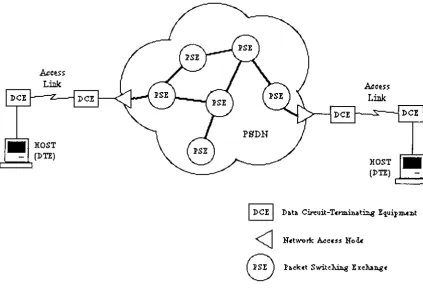
A PSDN is a wide-area network (WAN), in contrast to a local-area network (LAN) such as Ethernet. Wide area networks consist of widely distributed packet switching exchanges (PSE) which are connected together using high-speed lines. A host device commonly known as Data Terminating Equipment (DTE) is connected to the PSDN via a modem, commonly known as Data Circuit Terminating Equipment (DCE). A Network Access Protocol is used for exchanging information across the access link to the PSDN. The PSDN can then be relied upon to transport information reliably to the remote DCE and DTE.
advantage over other networking vendors in that they have access to very high-speed and very reliable links.
HOST
(DTE)~===~
I
DCEI
Data C:ircuit-Tcnni:n.at~ Equip:m.ui..t [image:19.599.72.496.133.426.2],<J
Network A.ccu$ Noue
Packet Switc~ :i: XCMJl8CFigure 2.1 - Topology of a Packet Switching Data Network
2.2 CCITI X.25 Recommendations
2.3 The Structure of X.25
X.25 is made up of three distinct layers corresponding closely to levels 1, 2 and 3 of the OSI reference model architecture (figure 1.1). The procedures at one layer utilise the functions of the layer immediately below but do not assume any knowledge of its implementation. The X.25 specification defines the format and meaning of the information exchanged across the DTE-DCE interface for these three layers.
Layer 1 is the physical layer. It references the X.21 and X.21 bis standards which define the digital and analog interfaces respectively. This layer deals with the electrical, mechanical, procedural and functional interface between the DTE and the DCE. It is characterized by bit-serial, synchronous, full-duplex, point-to-point connections.
The second layer (the data link layer) provides reliable communication between the DTE and the DCE for packets generated at level 3. X.25 provides error detection and flow control by using the frame structure of the High-Level Data Link Control (HDLC). The HDLC frame structure (figure 2.2) encapsulates the raw bits which are being transmitted. It
contains addressing information, control information and a Frame Checking Sequence (FCS). It is also preceded and succeeded by a special flag character. X.25 utilizes a Link Access Procedure (LAPB), a variant of HDLC, which specifies that either station may send commands at any time and initiate responses without receiving permission from the remote device.
~ - - - ~ - - - . . . - - - - . . . . - - - - f f - - - r - - - - " " T " " - - - - . J:'LAG ADDRESS CONTROL
DATA l'CS J:'LAG
( 16-bit$) (01111110) (01111110) (8-bit$) (8-bit$)
[image:20.600.89.471.483.514.2].__
___
.._____
..,_____
...____
,,
___
....______
_.____
...Figure 2.2- HDLC Frame Structure
2.4 Virtual Calls
Two kinds of connections are provided, these being virtual calls and permanent virtual circuits. A virtual call is analogous to an ordinary telephone call where a connection is established, data are transferred, and the connection is released. In contrast a permanent virtual circuit is like a leased line that is always present, and the DTE at either end can just send data whenever it wants to without any set-up.
Each virtual call is assigned a unique identifier by the originating DTE known as the logical channel number (or virtual circuit number). An X.25 terminal can support several virtual calls simultaneously, where each call is assigned a logical channel number and all packets related to that call carry that channel number. Both the DTE and its DCE use the same logical channel number. Hence X.25 layer 3 provides a multiplexing function by converting the single channel provided by layer 2 into a number of logical channels. The choice of circuit number on outgoing calls is determined by the DTE, and on incoming calls by theDCE.
A call collision occurs when the DTE sends an outgoing call and the DCE receives an incoming call, both choosing the same virtual circuit number for their respective calls. Since each call must have a unique virtual circuit number, the call collision is resolved by getting the DCE to abandon the incoming call and allowing the outgoing call to proceed. To minimize the chances of getting a call collision, the DTE normally chooses the highest available identifier for outgoing calls and the DCE chooses the lowest one for incoming calls.
2.5 X.25 Packet Formats
-I
--<H'I (0001)
I
Group I.og:i.c!al Cli.a:n.n.cl Idcnt:ili«rType (00001011) Cal.line I.e~t:h.
I
Callca. I.c~t:h.oo
I
l'acility I.c~t:h.l'acilit:i.«5
UHr Data
(11) l'ol".lll.1>t of t:h.c X.25 Call Rcq_uHt 11:n.d. h.,:o~ Call p11ck:ct5
8 'bit5
Q D 01 Group
I.og:i.c!al Cli.a:n.n.cl Idcnt:ili«r
P(R) 11 P(S) 0
User Data
( c) l' Ol".lll.1>t of t:h.c X .25 a.ata p11ck:ct5
-I
-
-
I
-
-8 'bit5
Gl'I (0001)
I
Group I.og:i.c!al Cli.an.nd Idcnt:ili«rType (00001111) Cal.line I.e~t:h.
I
Callca. I.e~t:h.oo
I
1'11cilit:i.(5
-I
--('b) l' ol".lll.1>t of t:h.c X .25 Call acceptea. 11:n.d. C11ll Co:n.n.cctea. p11ck:et5
8 'bit5
Gl'I (0001)
I
Group I.og:i.c!al Cb:n.n.cl Idcnt:ili«rType (00010011) Clea~ C11usc Dillg:n.o5t:i.c! C11usc
Optu.I>.lll l'i«la.5
[image:22.600.308.463.79.532.2]( a.) l' ol".lll.1>t of t:h.c X .25 Clear Req_uut an.a Cle11r In.d.:i.c!11tui:n. pack:ct5
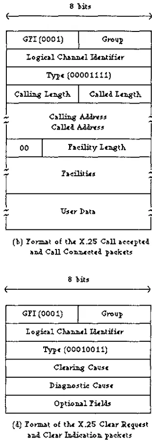
Figure 2.3 - Main X.25 Packet Formats
2.5.1 Call Set-up and Clearing Packets
passes it on to its DTE as a CALL CONNECTED packet. Thus when the originating DTE receives the CALL CONNECTED packet, the virtual circuit is established.
Once a virtual call has been established the full-duplex connection may be used to exchange data packets. When either side has had enough it sends a CLEAR REQUEST packet to the other side which arrives as a CLEAR INDICATION packet. The recipient DTE must respond with a CLEAR CONFIRMATION packet as an acknowledgement.
2.5.2 Data and Interrupt Packets
After the call set-up phase is completed and a virtual call has been established, data may be exchanged across the subnet in the form of data packets. These packets contain three octets of header information followed by Oto 128 octets of data.
An INTERRUPT packet is a high priority data packet which can overtake normal data packets to inform the destination DTE of a special event such as when a specific key has been struck on the remote DTE's keyboard. Unlike normal data packets, an INTERRUPT packet does not contain packet sequence counts and can therefore by-pass normal flow control procedures. Only one INTERRUPT packet may be outstanding in a virtual call at
any time and should be acknowledged with an INTERRUPT CONFIRMATION packet as
soon as possible.
2.5.3 Resetting and Restarting Packets
During the data transfer phase it may become necessary to reset a virtual call. For example, if a gap has been detected in the packet sequence numbers, the simplest solution will be to reinitialise the call so that it appears as though it has just been set up and then begin the data transfer phase again. This can be done by issuing a RESET REQUEST packet to the remote DTE which must respond with a RESET CONFIRMATION packet. Resetting a call will result in the next expected sequence number being set to 0 and all data packets in the network being discarded.
2.6 Flow Control
The third octet inside a data packet contains two sequence numbers, P(S) and P(R). These represent the number of data packets that have been sent and received respectively. When X.25 was first introduced these were only of significance across the DTE-DCE interface and were not used for end-to-end flow control. This was because X.25 was intended as an interface specification and therefore no assumptions could be made that the number of packets identified by P(R) had actually reached the destination DTE. This lack of end-to-end significance caused much concern and the 1980 revision introduced the D (delivery confirmation) bit for end-to-end flow control.
The D bit is bit 7 in octet 1 of the header in a data packet. If D is O in a data packet, then the P(S) and P(R) counts are of significance across the local DTE-DCE interface only and are independent of network propagation delays. As a result there could be many packets in transit at the same time in the network, which was the intention of the original recommendation. If D is 1 in a data packet, then it can be assumed that P(R) number of packets have reached the destination. The use of this facility requires additional communication between the DCEs which results in a significantly lower throughput especially on large networks where the sending DCE must wait for delivery confirmation from the remote DCE before acknowledging packets to its DTE.
The M (more data) bit is bit 5 in octet 2 of the header in a data packet. This bit is set to indicate to the receiving DTE that the logical unit of data is longer than can be fitted into a data packet and has therefore been divided into a sequence of smaller packets. In such a sequence all but the final data packet will have the M bit set to 1. The M bit is provided for higher level protocols and is not usually used by X.25 except in cases where the network may concatenate two or more short packets with the M bit set for reasons of operational efficiency.
2.7 Packet Assembly/Disassembly Devices
A terminal that can assemble and disassemble X.25 packets is referred to as a packet-mode DTE. Normally computers act as the packet assembler/disassembler (PAD) for a number of character-mode terminals which are connected to it. Character mode terminals cannot be connected directly to a PSDN. Instead, they must be connected to a PAD facility on the PSDN which performs the necessary packet assembly/disassembly.
2.8 Efficiency Considerations
PSDNs make an effort to work efficiently. Within the network there will normally be packets in transit belonging to several users. The PSDN uses a procedure called packet interleaving which uses gaps in the flow of packets to carry new packets entering the network. This means that a particular user's packets will not necessarily flow through the network consecutively. By filling these gaps wherever possible, PSDNs can use their lines to full capacity. The PSDN does guarantee that a user's packets is received in the same order in which they were sent, and that two or more users' packets will not get mixed up.
PSDNs are responsible for routing packets through the network. This means that packets may have to be rerouted if the chosen path is not available or may not be the most efficient. Regardless of the path that is taken, packets still arrive intact and in the correct order at the destination.
When a packet arrives at its destination, the PSDN sends an acknowledgment from the remote DCE. A DTE may transmit more packets as acknowledgements arrive for previous packets that were sent. The windowsize is the number of packets which may be transmitted without an acknowledgement. The windowsize limits the maximum number of packets which have not yet been acknowledged. If the windowsize is reached then no more packets can be sent until an acknowledgement arrives. Incoming acknowledgements are often carried by packets that are also carrying data for maximum networking efficiency.
CHAPTER3
THE INTERNET PROTOCOL SUITE
3.1 Background
The Internet is a collection of networks comprising of a number of local area networks at university and research institutions, regional and military networks. These networks are connected to each other and allow users to send messages from any of them to any other except where restrictions have been imposed for security reasons.
The Internet Protocol Suite is a set of protocols developed to allow computers to communicate among host computers across the Internet. The suite includes protocols such as User Datagram Protocol (UDP), Internet Control Message Protocol (ICMP), Transmission Control Protocol (TCP) and Internet Protocol (IP). Of these, TCP and IP are the best known and therefore the Internet Protocol Suite has become commonly known as TCP/IP.
Initially TCP/IP was used mostly between mainframes or minicomputers and so TCP/IP was traditionally used for:
a) File Transfer - The File Transfer Protocol (FTP) allows a user to get files from, or send files to another computer. The user has to provide a usercode and a password before being allowed to proceed with the transfer. Provisions are made for handling file transfers between machines with different character sets.
b) Remote Login - The Network Terminal Protocol (TELNET) allows a user to log in on any other computer on the network. A remote session is started by specifying the computer to connect to, as well as a usercode and a password. The TELNET program uses this information to log into the remote computer and thereafter whatever is typed on the local keyboard is transmitted to the remote machine. The session is terminated by logging off the remote computer at which point the TELNET program exits and control of the local computer is restored.
microcomputers. A primary problem was that microcomputers were often switched off when not in use, and the mail programs worked on the assumption that these machines were always on. For this reason, nowadays mail is normally handled by a larger system where a mail server is running at all times. When switched on, the user's computer retrieves mail from the mail server.
These services should be present in any implementation of TCP/IP, with the exception of some micro-based implementations which may not support computer mail.
3 .2 Layering in the Internet
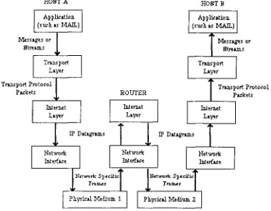
The Internet Protocol Suite is a layered set of protocols. In a similar fashion to the layering principles described in section 1 .4, a layer provides services to the layer above whilst shielding it from the implementation details of the layer below. Generally TCP/IP applications are modelled on the TCP/IP Internet layering model (figure 1.2) as follows:
~s
St
HOST A Application. (such. as MAIL)
sages or rtllllS
'.,
Trui.sport fayer HOSTB Application. (such. as MAIL)....
~ss ages or llllS Strt Trui.sport
fayer rotocol
Trui.sport P
hcke ts ROUTER
...
TOOl.Spo rt Protocol
t.ckets
p
',
In.tern.et
I
In.t e met
I
In.t e metfayer fayer fayer
...
.
"'
IPDat~s IP Dat~s
', '.,,
Network Network Network In.terbce In.terfa.ce In.t erfa.c e
.
"'.
"'
N(tw-ork Sp(cifi<: N(tworll: Sp(cifi<:
l'n,m.u l'n,m.u
..
',
I
Ph.ysicil ~di'\l.lll. 1 [image:29.599.85.478.359.665.2]I I
Ph.ysicil ~di'\l.lll. 2I
An application such as mail is written at the topmost layer. The application communicates with a similar mail application on a peer host by breaking down its transmission into messages. The messages are passed to the transport layer to a protocol such as UDP, TCP or ICMP. The transport layer protocol encapsulates the message into packets which are then passed to the Internet layer below. The Internet layer takes these packets and encapsulates them into IP datagrams. The IP datagrams are passed to a network-specific protocol which is used to manage a specific medium such as Ethernet. The network-specific protocol encapsulates the IP datagrams passed to it from the layer above into frames. These frames are then transmitted along the physical medium.
TCP /IP is based on the assumption that a large number of independent networks have been connected together by IP-layer routers. A router is a switch that receives data transmission units from input interfaces, and depending on the addresses in those units, routes them to the appropriate output interfaces. The user should therefore be able to access other computers and resources on any of these networks. Datagrams will often pass through a number of different networks before reaching their final destination and the routing needed for this should be completely invisible to the user.
In figure 3.1, frames are passed from Host A on one network to Host B on a different network via the router which connects both networks. When a frame arrives at Host B's network, it is sent upwards through the layers. Information is decapsulated at each layer until the original message is extracted and passed to the mail application.
3.3 Internet Addressing
the networking software searches the database for the name and comes up with the corresponding Internet address.
Similar to X.25 which works on the concept of a virtual circuit, the TCP at the transport layer is connection-oriented but accesses the underlying network by utilizing the services of the connectionless IP at the network layer. A stream of data is systematically encapsulated into a number of frames and each frame is sent individually through the network. The network does not assume that the frames are related in any way and it is quite likely that two logically consecutive frames may arrive at their destination via different routes. It is also possible that some frames may not get through because of an error and may have to be sent again.
3.4 The Transmission Control Protocol (TCP)
32 :bits
Source Port Destinh.tion Port Seque:n.ce N1.llll.:ber
Ackn.owh<lgem.e:n.t N1.llll.:ber
Offset
I
Re:s«rNd.I
Code WindowC:h.ecks1.llll. Urg-e:n.t Po:i:n.ter Options
I
Pwli:ng [image:32.600.126.435.79.276.2]DATA
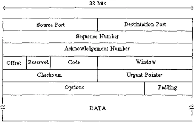
Figure 3.2 -TCP Packet Format
The TCP packet header contains information such as the source and destination port number and sequence number. The port numbers are used to keep track of different connections and the sequence number is used to reassemble the packets at the destination in the correct order. For error checking, a checksum is also included in the header which is used by TCP on the destination host to ensure that the packet received has not been altered in any way.
The TCP provides end-to-end flow control with the use of an acknowledgement field in the packet header. In order to ensure that a packet has arrived at its destination, the recipient sends back an acknowledgement packet which has the acknowledgement field containing the number of octets received so far. The sender repeats the transmission if it does not receive an acknowledgement packet within a certain length.
incoming packets prior to processing. Often the same packet is used for acknowledging the receipt of data and specifying the amount of new data which can be sent.
Similar to the X.25 INTERRUPT packet, TCP's urgent field in the packet header can be used to inform the other end of a specific event, for example if the user typed a control character. It is up to the application protocol to decide how this is handled.
3 .5 The Internet Protocol (IP)
The packets which have been created in the TCP are passed down to the IP at the network layer. The IP in TCP/IP is a connectionless service which is responsible for routing individual packets through the network to their assigned destination. The TCP must provide information about where to send the packets and it is the IP's job to find a suitable route to the destination.
IP encapsulates TCP packets into IP datagrams by appending its own headers:
~
~
32 :bits
Versioll.
I
Le~1I
Type of Service TotAl Le~1 Llen.tifica..tioll. FagsI
Fr,g:m.en.t Offset Tim.e to LiveI
Protocol Heilir Ch.ecks'l.llil. So1.1YCe IP AddressD estilla..tio ll. IP .Address
Optioll.S
I
Pilling [image:33.596.121.430.376.570.2]DATA
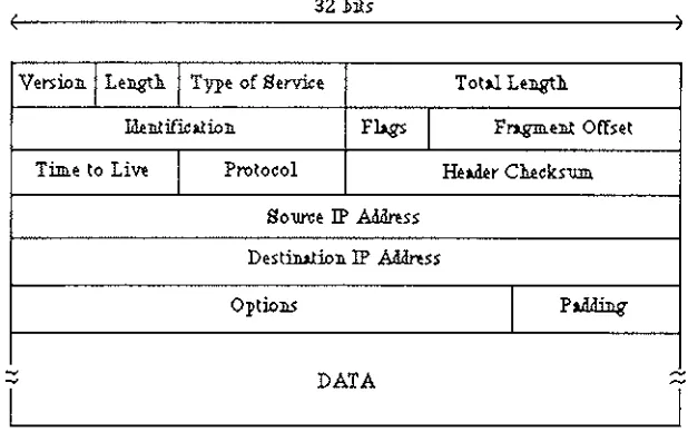
Figure 3.3 - IP Datagram Format
The length field gives the length of the header, measured in 32-bit words. The most common type of header (without options) is 20 octets long, so the length field contains a value of
5.
The total length field gives the length of the whole IP datagram, including the header.The type of service field specifies how the datagram should be handled. The field is subdivided into a number of smaller fields called Precedence, D, T & R. The Precedence field is used to give the datagram a precedence ranging from Oto 7. This describes the importance of each datagram. The D bit requests low delay, the T bit requests high throughput, and the R bit requests high reliability.
This header contains information such as the 32-bit source and destination Internet addresses, a protocol number and another checksum. The source Internet address is included so that the destination machine knows where the datagram originated from. The destination Internet address is necessary for gateways between networks to know in which direction to forward the datagram so that it will eventually reach its destination. The protocol number is used to tell the remote machine which protocol the datagram belongs to. Because TCP/IP is a layered protocol suite where protocols such as TCP, UDP and ICMP use IP as the primary transportation mechanism, the remote host must be told the nature of the datagram so that it is interpreted correctly.
The time to live field specifies how long (in seconds) the datagram is allowed to remain in the Internet system. Whenever a host transmits a datagram into the system, it sets a maximum time that the datagram should survive. Each router along the path from the source host to the destination host checks the time remaining when they process the datagram. Routers decrement the time to live value by one unit if the time to live is greater than zero, otherwise they discard the datagram if the time to live has reached zero. This ensures that a datagram does not travel in the Internet forever.
3.6 Underlying Network Services
CHAPTER4
UNDERLYING NETWORK SERVICES
Chapters 2 and 3 described two protocols which are based on the OSI Reference Model. The protocols X.25 and TCP/IP have network architectures comprising of layered protocols. It can be seen from figure 1.1 that underneath the network layer lies the data link layer and the physical layer. The data link layer provides an error free channel for the network layer above. The physical layer transmits the raw data bits across the medium.
A number of different physical mediums can be used. The data link layer protocol that is used depends on the physical medium. Together, the physical medium and its data link protocol provide underlying network services to the layers above. This chapter describes some of these network services.
4.1 Link Access Protocol B (LAPB)
IBM's Synchronous Data Link Control (SDLC) protocol is a data link level protocol which was submitted for acceptance as an international standard. Instead, it was modified by ISO to become HDLC (High-level Data Link Control). CCITT then adopted and modified HDLC to LAPB as part of the X.25 network interface standard.
4.1.1 LAPB Frame Format
LAPB shares the same frame format as HDLC (figure 2.2). There are three types of LAPB frames. The Control field is used differently depending on the type of the LAPB frame. Not all frames contain a Data field, but the other fields are always present. The Data field contains arbitrary information ranging from user data to diagnostic information for use by LAPB. The Data field may in theory be of any length, although in practice many implementations insist on it being an exact number of octets long. The frame does not specify the length of the Data field. Instead, it is possible for a link to detect the frame delimiter (Flag field) and calculate the length of the Data field.
sequence cannot appear inside a frame. When there are no frames to be sent on the link, the flag sequence may be repeated indefinitely.
The Address field is used in one of two ways. On multidrop lines, it is used to identify one of the terminals. On point-to-point lines, it is sometimes used to distinguish commands from responses.
The Frame Check Sequence (FCS) field is a variation of the cyclic redundancy code, using CRC-CCITT as the generator polynomial. The variation allows lost Flag octets to be detected.
4.1.2 LAPB Frame Types
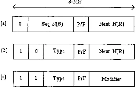
There are three types of LAPB frames. These are Information, Supervisory, and Unnumbered. The Control field is used differently depending on the type of the LAPB frame:
8-:bits
(a) O Seq N(S)
I
P/F
I
Next N(R)(:b) 1 0 Type
I
P/FI
Next N(R)( c) 1 1
[image:36.599.168.392.377.523.2]Type
I
P/FI
M.od.ifi.erFigure 4.1 - Control field of a LABP frame
Information Frames
Information frames are used to send user data. The principle type of data is X.25 packets. The data is transported inside the Data field of the LAPB frame. The frame type is determined by the first bit of the Control field, which is a 0.
frame plus one. In other words, it is the sequence number of the next unacknowledged frame. It also uses modulo-8 sequencing.
The P/F bit stands for Poll/Final. It is used when a computer is polling a group of terminals. When polling, the computer sets the bit to P. When the terminal responds, all frames sent by the terminal except the last one have the bit set to P. The final frame has the bit set to F.
Supervisory Frames
Supervisory frames are used to send commands. They do not contain an information field. The frame type is determined by the first two bits of the Control field, these being 10. There are various kinds of Supervisory frames, these being identified by the Type field. There are three types of Supervisory frames in LAPB. Type O frames are called RECEIVE READY, these being used to indicate the next frame expected.
Type 1 frames are called REJECT, these being negative acknowledgement frames used to indicate that a transmission error has been detected. The Next field indicates the first frame in the sequence which has not been correctly received, therefore requiring re-transmission. The sender must re-send all frames starting at N(R).
Type 2 frames are called RECEIVE NOT READY, and is used to tell the sender to stop sending because there are temporary problems at the receiver, such as a shortage of buffer space. It acknowledges all frames up to but not including N(R).
The P/F bit is used to force the other machine to send a Supervisory frame containing window information, rather than waiting for a normal transmission of this information.
Unnumbered Frames
SABM (Set Asynchronous Balanced Mode) resets the line and declares the sender and the receiver as equals. SABME and SNRME are similar to SABM and SNRM respectively, except that they specify an extended frame format using modulo-128 sequencing.
4.2 Bus Networks
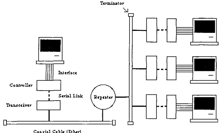
A bus network is characterized by a single coaxial cable called the bus which is run through one or more rooms. Hosts and associated interfaces are 'tapped' into the cable at any point. There is no central point, and all connections to the cable have an equal status. If a single coaxial cable is insufficient, then several sections can be joined together using devices called repeaters. Up to two repeaters may be placed between any two machines, making the total length about 1500 meters.
The advantages of such an arrangement are immense. Because all points on the cable have an equal status, hosts can be moved around freely. They are simply 'pulled out' of the cable and 'pushed in' elsewhere on the cable. Network broadcasting is simplified since any signals which are fed into the cable must reach all hosts tapped into it.
Hosts are connected to the coaxial cable by means of devices called tranceivers. These devices listen to the cable and can also transmit on the cable. Information placed on the cable by a transceiver will be propagated along it and reach all other transceivers. Thus by listening to the cable, a transceiver can 'hear' the traffic and pass on any frames heard on the cable to its host. The transceiver is connected to the host via a controller board. The controller has several functions. It encapsulates data from its host into a frame and passes it to the transceiver for sending. It also receives frames from the transceiver, decapsulates the data and passes on to its host whatever is intended for it.
Ethernet is one implementation of a bus network. It was originally developed in the early 1970's by Xerox Corporation to connect office workstations to computers and filestores. The main design aims included low running cost, reliability, no central controller, easy access to the transmission medium for all hosts, and suitability for handling 'bursty' traffic. The name "Ethernet" was derived from the coaxial cable called the ether.
-
-Co:n.trollitr
Sera 1 I.ink
[image:40.599.93.464.79.305.2]-Coa xi.al Ca 'blc (Eth.er)
Figure 4.2 - Bus network Topology
a) Token Passing - This technique requires one station to generate tokens which are then passed between stations. A station must receive a token before it is allowed to transmit on the ether. It may however decline the offer to transmit, in which case it must pass on the token to another (pre-determined) station. The station which possess the token may transmit one or more frames of data to any destination. When it has finished transmitting, it must pass on the token to the next station.
b) Carrier Sense Multiple Access (CSMA) - This is a technique where the transceiver listens to see if the ether is free and if so, it transmits data but does not listen to what it has just sent. Under heavy loading, collisions will occur which will not be detected. Re-transmissions initiated by a higher level protocol will be necessary, and this will add to the congestion. CSMA is the simplest technique and it is normally used with the Collision Avoidance (CA) or the Collision Detection (CD) techniques described below, rather than on its own.
therefore preventing collisions even further. If all timeslots are unused, then the network enters a free-for-all state in which any station can transmit. Collisions may occur at this stage if more than one station chooses to transmit, in which case the transmissions are not acknowledged but are re-transmitted in an orderly fashion during the next round of timeslots. In the free-for-all state, no attempt is made to detect collisions.
A major problem with the CSMA/CA technique is that the more stations there are, the greater the number of timeslots which will be required. Consequently, there will be an increase in the number of unused timeslots leading to a wastage in bandwidth. Also, the longer the ether becomes, the longer each timeslots will have to be to ensure that no collisions occur. Therefore, CSMA/CA is best suited for networks with a small number of hosts in a small, localized area.
d) Carrier Sense Multiple Access with Collision Detection (CSMA/CD) - The Collision Detection Technique is the one used in standard Ethernet implementations. This was developed by the IEEE as part of the 802 collection of standards. CSMA/CD is discussed below.
4.3 IEEE 802
The IEEE 802 is a collection of standards for local area networks. The standards are divided into parts, each published as a separate book. The 802.1 standard gives an introduction to the set of standards. The 802.2 standard describes the Logical Link Control (LLC) protocol. Standards 802.3 through 802.5 describe the CSMNCD, token bus, and token ring protocols respectively.
IEEE 802 divides the data link layer into two sections. The lower section is called the Medium Access Control (MAC) sublayer which has three variants, namely CSMA/CD, token bus and token ring. The upper section is called the Logical Link Control (LLC) sublayer.
4.3.1 IEEE 802.2 (LLC)
The LLC sublayer provides either a connectionless (type 1) or a connection-oriented (type 2) service to the network layer above. With the connectionless service, the LLC sublayer accepts a packet from the network layer and sends the packet to the destination with no acknowledgement or guarantee of delivery. When the connection-oriented service is used, a connection must first be set up between the source and the destination. The connection is then used to transmit packets from the network layer in order with guaranteed delivery. When the connection is no longer required, it is released.
The LLC services are made available to the network layer by means of primitives. In the
OSI model, the service primitives can be divided into four classes:
a) Request Primitive - The Request primitive is used to request a specific task from the service, such as proposing a new connection with a remote host.
b) Indication Primitive - The proposal for the new connection reaches the remote host in the form of an Indication primitive.
c) Response Primitive -The remote host uses the Response primitive to accept or reject the proposed connection.
d) Confirm Primitive - The initiating host uses the Confirm primitive to find out the remote host's decision.
of L_CONNECTION_FLOWCONTROL and is used to regulate the flow of information between the network layer and the data link layer.
The LLC frame structure is similar to that of HDLC:
- - - - ~ - - - ~ - - - ~ - - - H ~
DSAP a<ldrc:s:s SSAP a<ldrc:s:s Con.trol
DATA
(8-'bit:s) (8-'bit:s) ( 16-'bit:s)
[image:43.599.144.416.171.205.2]- - - ~ - - - f f
Figure 4.3 - The IEEE 802 LLC Frame Format
DSAP and SSAP are Destination Service Access Point and Source Service Access Point respectively. Each layer in the OSI model provides a service to the layer above it. A service access point is the point where a layer n+ 1 can access the services offered by layer n below. When a connection is set up, the network layer pushes a service request through the Source Service Access Point (SSAP) and the request emerges at the remote end at the Destination Service Access Point (DSAP). The SSAP-DSAP pair identifies a connection and is used for the duration of the connection.
The control field is similar to the control field in the LAPB and HDLC protocols (figure 4.1). However, there are some differences between LLC and the others. Firstly, LLC allows a 16-bit control field. This allows the inclusion of a 7-bit sequence number. Secondly, the LLC protocol only supports asynchronous balanced mode supporting peer-to-peer communication, not computers polling terminals. Thirdly, two new frame types have been included in addition to the Information, Supervisory and Unnumbered frame types. These are the Exchange Identification (XID) frame for communicating information between LLC peers about service types and window sizes, and the TEST frame for requesting the other side to generate a response to test the connection.
4.3.2 IEEE 802.3 (CSMNCD)
The Canier Sense Multiple Access with Collision Detection (CSMA/CD) technique is used in standard Ethernet implementations. It exists within implementations as the lower data link layer (MAC sublayer).
CSMNCD works as follows. If a transceiver detects a collision it briefly jams the ether
using a special signal to warn other transceivers not to transmit anything. Then it can either try again immediately, try again after a random period of time or adopt a combination of both approaches. The first option of trying again immediately is not usually suitable because another transceiver may do exactly the same thing, therefore leading to another collision. The second option of waiting for a random length of time is the standard CSMA/CD technique. In this implementation, transceivers must wait until the delay has elapsed before transmitting, even if the ether is free, so it is not entirely efficient. Some implementations elect to use a combination of trying again immediately and waiting for a random length of time before trying again. This is achieved by sometimes trying again immediately, and at other times waiting for a random length of time. The probability used to decide which method to use must be calculated carefully to avoid the problem in the first option.
A break in the coaxial cable will appear as if the cable is unterminated. Therefore, frames that are normally absorbed by a terminator will be reflected back along the cable, causing collisions. Therefore if all frames from all transceivers appear to be colliding, this is indicative of a cable fault. It is also possible for a faulty transceiver to jam the cable continuously.
Ethernet
Ethernet is an example of a CSMNCD local area network. Like the addressing provided by
An Ethernet frame has the following format:
[image:45.600.73.495.118.151.2]Pru.m.:ble Dest Address So~e Address Pa.cket Type Dtb. CRC (64 :bi.ts) ( 48 :bi.ts) ( 48 :bi.ts) ( 16 :bi.ts) (32 :bi.ts)
Figure 4.4 - Ethernet Frame Format
A frame contains a 14-octet header containing a destination Ethernet address, a source Ethernet address and a type code. Each machine's controller listens only for frames destined for itself. The type code allows several different protocol suites such as TCP/IP, DECnet etc, to use the Ethernet. Each suite has an identifier which is copied into the type code field. TCP/IP's use of Ethernet is discussed later.
Following the header is the datagram specific to the protocol suite. In TCP/IP for example, the data field will hold an IP datagram. Finally, there is a checksum calculated by the Ethernet controller.
4.4 IP over Ethernet
The procedure for transmitting IP datagrams over Ethernet is now discussed. IP datagrams may be encapsulated and transmitted within Ethernet frames, as discussed earlier. The Ethernet frame header contains a number of fields including the destination Ethernet address, the source Ethernet address and the type of protocol it is supporting.
4.4.1 Address Resolution Protocol
When an IP datagram is encapsulated inside an Ethernet frame, the destination field of the latter must be filled in with a 48-bit Ethernet address. In other words, there must be a way of finding out the Ethernet address of the host identified by the 32-bit Internet address. The mapping of the 32-bit Internet address to a 48-bit Ethernet address is done using the Address Resolution Protocol (ARP).
ARP is not a member of the TCP/IP suite. The protocol works as follows. When given an IP datagram containing a 32-bit Internet address such as 130.123.3.10, the system accesses a lookup table containing a list of all hosts on the local network along with their Internet addresses and Ethernet addresses. This list is searched for the appropriate Internet address, and if it is found then its associated Ethernet address is copied into the destination field of the Ethernet frame header. If the Internet address is not found, then the protocol broadcasts an ARP request. Essentially an ARP request says "I need an Ethernet address for 130.123.3.10". All hosts must listen to ARP requests, and the host to which the Internet address belongs is expected to reply with its 48-bit Ethernet address. The requesting host receives this information and uses it to send future frames directly to the destination host. Although hosts which do not have an Internet address as that requested in the Address Resolution Protocol are expected to ignore the ARP requests, some hosts may use the ARP request to update their own knowledge about other hosts on the network, although they are not directly involved.
4.4.2 Ethernet Frame Contents for IP
The data field contains the IP datagram consisting of the IP header followed immediately by the data. The data field has a minimum length of 46 octets, and therefore it should be null padded if necessary. Note that this padding is not considered to be a part of the IP datagram and is not included in the total length field of the IP header.
The data field has a maximum length of 1500 octets. This means that the maximum size of an IP datagram is 1500 octets. Implementations are encouraged to support full-length packets and gateways on the Internet must be able to accept full-length packets and fragment them if necessary. A system which cannot accept full-length packets discourages others from sending them by using the TCP Maximum Segment Size Option.
4.4.3 TCP Maximum Segment Size Option
During the connection establishment phase, TCP provides an option to indicate the maximum size TCP segment that can be accepted on that connection. This announcement is sent from the receiving host to the sending host and effectively says "I can accept TCP segments up to size X". The value of X may be larger or smaller than the default value. Similarly, the sending host sends a maximum segment size which is suitable for itself. The smaller of the two values is then used for the remainder of the connection.
The TCP Maximum Segment Size counts only the data octets in the segment. It does not count the TCP header or the IP header. The TCP Maximum Segment Size is thus defined as being the IP maximum datagram size minus 40 octets. For example, the default IP maximum datagram size is 576 octets, so the TCP maximum segment size is 536 octets.
4.4.4 Datagram Fragmentation
network which cannot handle packets larger than 1000 octets. It then becomes necessary for the Ethernet packets to be fragmented into two or more smaller pieces, pass through the intermediate network, and then be reassembled after passing through. The IP header contains fields to indicate that its datagram has been fragmented, and contains enough information for the datagrams to be reassembled in the correct order.
It is fairly common for implementations to use 576 octet datagrams whenever it is uncertain whether intermediate networks can cope with larger datagrams. This strategy is adopted because the reassembly algorithms in some intermediate networks have been found to be faulty. The maximum size datagram that all hosts must be able to accept, or reassemble from fragments is 576 octets. Hosts may accept larger fragments and assemble these into larger datagrams as they wish.
4.5 X.25 over CSMAfCD
The JNT Ethernet Advisory Group is a technical committee responsible for defining the implementation details of connection-oriented protocols on CSMA/CD local area networks. A report produced in 1985 provided the details for implementing X.25 over CSMA/CD LANs.
4.5.1 Data Link Layer Management
The X.25 over CSMA/CD implementation must support both connectionless (type 1) and connection-oriented (type 2) services as described in section 4.3.1. An implementation can choose to omit the generating of TEST and Exchange Identification (XID) frames but must provide a means of responding to these. However, the XID frame generation feature is strongly recommended to support link window size negotiation as described below.
A LAN station that wishes to set up a virtual call with another LAN station must initiate a link establishment phase if a link does not already exist. A LAN station may support many link connections. An inactive link is one which after establishment has never sustained any X.25 virtual calls, or has sustained virtual calls but all of these have been cleared. For reasons of efficiency, inactive links are disconnected.
Links are disconnected as follows. A LAN station maintains a count of established X.25 virtual calls. This count is initialised to zero following the restart procedure, and an internal timer is started. When an X.25 CALL CONNECTED packet is received or a CALL ACCEPT packet is sent in response to a CALL REQUEST or INCOMING CALL respectively, the timer stopped if the count is zero and the count is incremented. When a CLEAR CONFIRMATION is sent or received in response to a CLEAR REQUEST or CLEAR INDICATION, the count is decremented and the timer is restarted if the count
becomes zero. If a REST ART REQUEST is sent or a REST ART INDICATION is received
and the count is non-zero, then the count is set to zero and the timer is re-started. If the timer expires, the link is disconnected.
A number of link parameters may be used to configure the nature of the link:
determine the receive window sizes for each end-point of the link. The XID frame exchange comprises of a command and a response. If a station cannot support a window size of 127 then it must use the XID command to inform the remote LAN station of the maximum window size that it can support. Each station is responsible for generating an XID command if necessary, and should not rely on the XID response to indicate its maximum window size. The window size can be changed at any time by either station issuing an XID command. XID command frames which are received before a link is established are ignored. When a link is established, the default window size of 127 is assumed until an XID command frame is issued or received.
b) Maximum number of octets in an PDU -The Medium Access Control (MAC) sublayer places a restriction of 1518 octets per frame. The presence of header information in the frame therefore restricts the maximum number of octets in a PDU to 1030 octets.
The minimum number of octets in an in a PDU is 262. This is because the maximum length of the facility field in a CALL REQUEST packet is 109 octets, and the maximum size of the user data field of the X.25 fast select CALL REQUEST packet is 128, therefore requiring an information field of 256 octets. With the addition of packet headers and addressing information, the minimum becomes 262 octets.
c) Acknowledgement Timer -This is a timer which measures the interval during which an acknowledgement to one or more outstanding PDUs can be expected by the LLC. The suggested value for this timer is 0.3 seconds but may be set to an alternate value.
d) P bit Timer - This is a timer which measures the interval during which the LLC can expect to receive a PDU with the final (F) bit set in response to a type 2 command with the poll (P) bit set. The suggested value for this timer is 0.1 seconds.
e) Reject Timer - This is a timer which measures the interval during which the LLC can expect to receive a reply to a rejected PDU. The suggested value for this timer is 0.1 seconds.