multi-path relay channels
.
White Rose Research Online URL for this paper:
http://eprints.whiterose.ac.uk/100451/
Version: Accepted Version
Article:
Li, Q., Yu, M., Pandharipande, A. et al. (3 more authors) (2016) Performance of virtual
full-duplex relaying on cooperative multi-path relay channels. IEEE Transactions on
Wireless Communications, 15 (5). pp. 3628-3642. ISSN 1536-1276
https://doi.org/10.1109/TWC.2016.2523995
© 2016 IEEE. Personal use of this material is permitted. Permission from IEEE must be
obtained for all other users, including reprinting/ republishing this material for advertising or
promotional purposes, creating new collective works for resale or redistribution to servers
or lists, or reuse of any copyrighted components of this work in other works.
[email protected] https://eprints.whiterose.ac.uk/
Reuse
Unless indicated otherwise, fulltext items are protected by copyright with all rights reserved. The copyright exception in section 29 of the Copyright, Designs and Patents Act 1988 allows the making of a single copy solely for the purpose of non-commercial research or private study within the limits of fair dealing. The publisher or other rights-holder may allow further reproduction and re-use of this version - refer to the White Rose Research Online record for this item. Where records identify the publisher as the copyright holder, users can verify any specific terms of use on the publisher’s website.
Takedown
If you consider content in White Rose Research Online to be in breach of UK law, please notify us by
Performance of Virtual Full-Duplex Relaying on
Cooperative Multi-Path Relay Channels
Qiang Li, Manli Yu, Ashish Pandharipande,
Senior Member, IEEE
, Xiaohu Ge,
Senior Member, IEEE
,
Jiliang Zhang,
Member, IEEE
, and Jie Zhang
Abstract—We consider a cooperative multi-path relay channel (MPRC) where multiple half-duplex relays assist in the packet transmissions from a source to its destination. A virtual full-duplex (FD) relaying scheme is proposed that allows the source to transmit a new packet simultaneously with the selected best relay, with the rest of the relays attempting to decode this new packet. Thus a new source packet can be served in each time slot, as in FD relay systems. Taking into account the effect of inter-relay interference (IRI) that is caused by simultaneous relay and source transmissions, a Markov chain analytical model is used to characterize the decoding performance at the relays, based on which the overall outage probability of MPRC is obtained in closed-form expressions. The asymptotic performance analysis reveals that in low rate scenarios, a close-to-full diversity order is achieved by the proposed scheme while substantially improving the spectrum efficiency. In high rate scenarios, the decoding performance of relays is limited by IRI and the system outage performance experiences an error floor. Simulation results demonstrate the performance gains of the proposed scheme by comparisons with existing half-duplex and FD relay systems in the literature.
Index Terms—Multi-path relay channels, half-duplex and full-duplex, opportunistic relaying, Markov chain, diversity.
I. INTRODUCTION
I
N this paper, we consider a cooperative multi-path relay channel (MPRC) as shown in Fig. 1(a). With multiple intermediate relay terminals to assist the packet transmissions from the source to its corresponding destination, a packet can be potentially delivered through multiple independent paths. This brings cooperative diversity gains [2], [3] that can effectively combat the effects of wireless fading and significantly improve the communication reliability in future networks, e.g., long-term evolution (LTE) and 5G [4]–[6]. InQiang Li, Manli Yu, and Xiaohu Ge (corresponding author) are with the Department of Electronics and Information Engineering, Huazhong University of Science and Technology, Wuhan 430074, Hubei, P. R. China. Emails:
{qli patrick, manli yu, xhge}@hust.edu.cn.
Ashish Pandharipande is with Philips Research, High Tech Campus, 5656 AE Eindhoven, Netherlands. Email: [email protected].
Jiliang Zhang is with Shenzhen Graduate School, Harbin Institute of Technology, Shenzhen 518055, P. R. China. Email: [email protected]. Jie Zhang is with Department of Electronic and Electrical Engineering, University of Sheffield, UK. Email: [email protected].
Part of this work has been reported in IEEE International Conference on Communication Workshop [1].
The authors would like to acknowledge the support from the National Natural Science Foundation of China (NSFC) under grants 61301128 and 61461136004, NFSC Major International Joint Research Project under grant 61210002, the Fundamental Research Funds for the Central Universities under the grant 2015XJGH011. This research is partially supported by the EU FP7-PEOPLE-IRSES, project acronym S2EuNet (grant no. 247083), project acronym WiNDOW (grant no. 318992) and project acronym CROWN (grant no. 610524).
order to exploit the inherent diversity gains of the cooperative MPRC, various relay selection schemes [7]–[9] have been proposed where a single or multiple best relays are selected to help forward the received source signal to the destination.
A MPRC with decode-and-forward (DF) relays was inves-tigated in [10], where a single best relay was selected oppor-tunistically using a distributed relay selection algorithm that requires only local channel knowledge. It was demonstrated that, in terms of the outage behavior, this opportunistic DF relaying is equivalent to the optimal DF protocol that employs all potential relays. A joint relay selection and cooperative beamforming method was proposed in [11], where the best two out of multiple intermediate relays were selected to forward the received signals through a common channel to the destination. Using two-bit quantized phase information of the channel gains from the two relays respectively to the destination, a full diversity order was achieved while bringing some performance gains. Relay selection schemes that aim at optimizing the outage performance of the MPRC with DF relays were investigated in [12] and [13], with and without a direct link between the source and destination, respectively. In [14], a DF-based cooperative multi-cast system was investigated. With an opportunistic relay selection, a lower bound of the outage probability and the diversity-multiplexing tradeoff were analyzed. In [15], the MPRC with amplify-and-forward (AF) and DF relays were investigated respectively with an interference-limited destination, i.e., there are multiple interferers located near the destination. Then a relay selection scheme was proposed to maximize the mutual information of the network. In [16], a successive relaying protocol was proposed in MPRC on relatively static channels. Within the duration that the channels remain unchanged, two relays are selected to assist the source transmissions alternatively, which enables the source to transmit a new packet in each time slot as in a two-path relay channel [22]. In addition, other relay selection schemes have also been proposed that aim at optimizing the energy efficiency or maximizing the lifetime of the MPRC with limited energy at the relays [19]–[21].
...
...
...
...
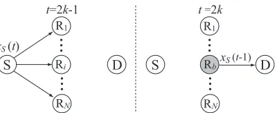
S D S D
R1 R1
Ri Rb
RN RN
x S(t)
x S(t-1)
t=2k-1 t =2k
(a) The conventional MPRC with half-duplex relays, i.e., HD-MPRC.
...
S
S Ri D Rb D
R1 R1
RN RN
x S(t) x S(t)
x S(t-1)
...
...
...
t=1 t ≥ 2
Rb selected best relay inter-relay interference
[image:3.612.77.277.51.133.2](b) The proposed virtual full-duplex relaying scheme on MPRC, i.e., VFD-MPRC.
Fig. 1. Illustrations of the cooperative multi-path relay channels (MPRC).
it takes only three (or two) time slots for an information exchange between the two end users, thus improving the spectrum efficiency while reserving some diversity gains [24]– [26]. In addition, virtual full-duplex (FD) relaying schemes with buffer equipped at the relay were investigated in [27]–[32] to recover the spectrum efficiency loss caused by half-duplex relaying. With a joint design of buffer-aided relay selection and beamforming, the source and the selected relay simultaneously transmit their information to another relay and the destination, thus delivering a new packet to the destination in each time slot. On the other hand, in order to improve the performance of the conventional full-duplex relay system that is limited by the residual self-interference, a hybrid full-duplex/half-duplex relaying scheme was proposed in [33].
A close look at the MPRC shown in Fig. 1(a) indicates that both the source S and all relays except the selected relay stay idle every other time slot. A question arises naturally as to whether it is possible for S to also transmit during the relay transmission, as in [27]–[35]? With this observation in mind, we propose a virtual full-duplex relaying scheme on MPRC (VFD-MPRC) by exploiting half-duplex relays that are equipped with only a single antenna, as shown in Fig. 1(b). Among the relays that successfully decode the current source packet, a single best relay in terms of the relay-destination channel is selected to forward the decoded packet to the des-tination in the subsequent time slot. Concurrently, S transmits a new packet and all rest relays attempt to decode this packet. Then among these available relays that successfully decode the source packet, a single best relay is similarly selected, so on and so forth. If all intermediate relays are regarded as a single “super relay”, then the considered MPRC becomes a full-duplex relay system through which a new source packet can be forwarded to the destination in each time slot. The contributions of this paper are summarized as follows.
• Taking into account the effect of inter-relay interference
(IRI) that is caused by the simultaneous transmissions from the source and the selected relay, as shown in Fig. 1(b), we use a Markov analytical model [34], [35] to analyze the decoding performance at the relays, where successive interference cancellation (SIC) is performed to decode the desired source packet that is subject to IRI. On this basis, the overall end-to-end outage probability of VFD-MPRC is derived in closed-form expressions.
• The asymptotic performance of VFD-MPRC in the high SNR regime is analyzed. Our results demonstrate that in low rate scenarios, a close-to-full diversity order can be achieved by the proposed approach while significantly recovering the spectrum inefficiency in the conventional HD relay systems. In high rate scenarios, since the desired signal is subject to a comparable IRI, the performance of SIC is limited and the proposed VFD-MPRC experiences an error floor and thus no diversity gain is available.
• Simulation results demonstrate significant performance
improvements achieved by the proposed VFD-MPRC over the conventional HD-MPRC in both low and modest SNR regimes, while HD-MPRC brings its advantage into play only in the high SNR regime where a full diversity order is achieved. Furthermore, by comparisons with existing full-duplex relay channels, a comparable performance can be achieved by the proposed approach while with only half-duplex relays.
Although a similar Markov analytical model to [1], [34], [35] is used in this paper, the proposed scheme can be applied to a general MPRC with non-symmetric relay channels, where the data source is able to transmit at an arbitrary target data rate. Furthermore, while [1], [34], [35] investigated the outage performance only, we attempt to also analyze the asymptotic performance of MPRC in the high SNR regime.
The rest of this paper is organized as follows. Section II describes the system model of the proposed VFD-MPRC. A Markov chain analytical model is introduced in Section III, based on which the end-to-end outage performance of VFD-MPRC is analyzed and closed-form expressions are derived in Section IV. Then the asymptotic system performance of VFD-MPRC is analyzed in Section V, where the diversity order and error floor are investigated. Simulation results and comparisons with existing work are presented in Section VI. Finally, Section VII concludes the paper.
II. SYSTEM MODEL AND PROTOCOL DESCRIPTION
As shown in Fig. 1(b), we consider a cooperative MPRC where a data source S communicates with its corresponding destination D with the assistance of N HD relays R1, R2,
· · ·, RN. Since there is a large distance between S and D,
the direct link from S→D is so weak that can be neglected. We leths,i,hi,d andhi,j denote the channel coefficients from S→Ri, Ri→D and Ri→Rj respectively, where i, j ∈ I =
hu,v ∼ CN(0, δu,v−1) where u ∈ {s,I}, v ∈ {I, d} and
u̸=v. Then we have the corresponding channel power gain
γu,v=|hu,v|2∼exp (δu,v)[36].
We define xS(t) as the packet originated at S in time slot t, which is transmitted with a pre-defined target data rateR0 bits/slot/Hz. The transmission powers at S and Ri are defined
as PS and Pi respectively where Pi = PR ∀ i ∈ I. The additive white Gaussian noise is defined as nr where r ∈ {I, d}, which is of zero mean and with unit variance.
In the considered VFD-MPRC, a data packet xS(t) is
transmitted from S in each time slot tand all available relays attempt to decode this packet, as illustrated in Fig. 1(b). For ease of exposition, we define an index set Id that contains
all relays that successfully decode xS(t), where Id ⊆ I.
If Id ̸= ∅, then a single best relay is selected from Id to
help forward xS(t) to the destination in the subsequent time slot t+ 1. Otherwise ifId =∅, then xS(t) is discarded and
an outage is declared. Without losing generality, we consider a data frame that consists of L + 1 time slots. Detailed transmission process is discussed in the following.
1) In the initial time slott= 1, S transmits a packetxS(1)
and the corresponding received signal at Ri wherei∈ I
is given as
yi(1) =hs,i√PSxS(1) +ni(1). (1)
All N relays attempts to decode this packet and the indices of the relays that correctly decode xS(1) are classified into Id. We assume that the channels are
reciprocal. To facilitate relay selection, D sends back a clear-to-send (CTS) message at the end of each time slot. Upon receiving the CTS message, each relay Ri, i∈ Idruns a countdown timer, the initial value of which
is inversely proportional to the estimated channel quality of the feedback channel from D. Then the best relay Rb
in terms of the instantaneous relay-destination channel condition, i.e.,
b= arg max
i∈Id
{|hi,d|2}= arg max i∈Id
{γi,d}, (2)
is automatically selected in a distributed manner [10]. 2) In the subsequent time slot t = 2, Rb proceeds to
forward the decoded packetxS(1)and S transmits a new
packet xS(2) simultaneously. Then the corresponding received signal at Ri wherei∈ I \b and D is given as
yi(2) = hs,i√PSxS(2)
+ hb,i √
PRxS(1) +ni(2), (3)
yd(2) = hb,d
√
PRxS(1) +nd(2). (4)
If however Id = ∅, then xS(1) is discarded and an
outage is declared. Then the corresponding received signal at Ri, fori∈ I, in slot t= 2 is given as
yi(2) =hs,i √
PSxS(2) +ni(2). (5)
3) The above steps repeat that in time slot t, if xS(t) is
successfully decoded by at least one relay, then a single best relay Rb is selected from Id to forward xS(t) in
the subsequent time slott+ 1. Then the corresponding
received signals at Ri wherei∈ I \b and D are given
as
yi(t+ 1) = hs,i√PSxS(t+ 1)
+ hb,i√PRxS(t) +ni(t+ 1), (6)
yd(t+ 1) = hb,d
√
PRxS(t) +nd(t+ 1), (7)
respectively. All the remaining N −1 relays attempt to decode xS(t + 1) that is subject to an IRI from xS(t) using successive interference cancellation (SIC)
[37], and D attempts to recover xS(t) from yd(t+ 1).
If however, none of the relays can decode xS(t), then xS(t) is simply discarded and an outage is declared. Thus the corresponding received signal at relay Riwhere i∈ I in time slot t+ 1 is given as
yi(t+ 1) =hs,i √
PSxS(t+ 1) +ni(t+ 1), (8)
and all N relays attempt to decode xS(t+ 1) without
IRI.
4) In the second last time slott=L, similarly ifxS(L)is successfully decoded by at least one relay, a single best relay Rb is selected to forward xS(L) in the last time
slotL+ 1, whereas S holds its transmission until a new frame starts. Then the corresponding received signal at D is given as
yd(L+ 1) =hb,d√PRxS(L) +nd(L+ 1). (9)
If however, none of the relays can decode xS(L), then an outage is declared.
Remark 1: For the implementation of SIC at the
interme-diate relay Ri [37], only channel state information (CSI) of
the two incoming channels S→Ri and Rb →Ri is required
at the receiver side Ri. This can be obtained through typical
channel estimation schemes by using training/pilot sequences [38], [39]. On the other hand, for the implementation of relay selection, assuming that the channels are reciprocal [10], the CSI of channel D→Ri is required at the receiver side Rionly.
Compared to existing schemes, e.g. [17] that requires global CSI, our scheme requires only local CSI at the receiver side and can be implemented with relatively small overhead.
III. A MARKOVCHAINANALYTICMODEL
According to the decoding results at the relays, we define two states H0 and H1 at the end of each time slot t, where t ∈ {1,2,· · ·, L}. H1 denotes the state that xS(t) is successfully decoded by at least one relay, i.e., Id ̸= ∅,
and H0 denotes the complementary state that Id = ∅. If
the relays are known to be in state H1 (or H0) in a certain time slot, then the corresponding outage probability of the destination can be easily analyzed. However, for a data frame that consists of multiple time slots, without knowing the exact system state in each time slot, it is intractable to analyze the overall average outage probability of the destination using conventional methods.
From the protocol description in Section II, conditioned on state H1 in time slot t, a best relay Rb is selected from Id
time slot t+ 1. This brings an IRI to the remaining N −1
relays that attempt to decode the new source packetxS(t+ 1)
transmitted in time slott+ 1. Conversely, conditioned on state
H0 in time slott,xS(t)is simply discarded and allN relays attempt to decode the new packet xS(t+ 1) without IRI in time slott+ 1. Thus, if the system is in stateH1 (or H0) in time slot t, then the relays will (or will not) suffer from the IRI in time slot t+ 1, which leads to quite different decoding results of the new packet xS(t+ 1). That is to say, whether xS(t+ 1) can be decoded and forwarded to the destination
depends on whether xS(t) has been decoded and forwarded.
This results in a dependence of the state in time slott+ 1on the state in time slot t.
Since this one-slot memory coincides with the property of a Markov chain in which the probability distribution of the next state depends only on the current state and not on the sequence of events that preceded it, we use a two-state Markov chain to describe the state transitions betweenH0andH1in successive time slots. For ease of description, we define π0 and π1 as the steady-state probabilities ofH0andH1respectively in the long term, and letP00,P01,P10andP11be the corresponding state-transition probabilities.
Then exploiting the properties of Markov chain [36], the stationary distribution of the system can be derived as
πP = π, (10)
π0+π1 = 1, (11)
whereπ= [π0 π1]denotes the steady-state probability vector
and P = [
P00 P01
P10 P11
]
denotes the transition probability
matrix. From (10) and (11), π can be obtained as
π=[ P10
P10+P01
P01
P10+P01
]
. (12)
Remark 2: From the above analysis, the steady-state
prob-abilities π1 and π0 characterize the decoding performance at the relays. To be specific, out ofLpackets transmitted from S where Lis a large finite value, π1L packets are successfully decoded and relayed to the destination on average, whereas the remaining π0L source packets fail to be decoded by the relays and are simply discarded. Thus π0 characterizes the outage probability at the relays.
IV. OUTAGEPERFORMANCEANALYSIS
Based on the Markov chain analytical model described in Section III, in this section we first analyze the state-transition probabilities P00, P01, P10 and P11 respectively, through which the outage performance at the relays can be charac-terized. Then we proceed to analyze the outage performance at the destination, such that the end-to-end outage probability of the proposed VFD-MPRC can be obtained.
A. Outage Performance at the Relays
Without losing generality, we consider a time slot t and analyze the state transitions from time slot t to t+ 1. Then according to the decoding results ofxS(t)at the relays in time
slott, i.e.,H0 andH1, we have the following cases.
1) Conditioned on stateH0in time slott: No IRI exists in
time slot t+ 1, in which allN relays attempt to decode the new source packet xS(t+ 1). From (8), with target rate R0, the probability that xS(t+ 1)is successfully decoded by Ri
wherei∈ I is given as
P01i = Pr{log2(1 +γs,iPS)≥R0}
= Pr
{
γs,i≥
γ0
PS
}
=e−
δs,iγ0
PS , (13)
where γ0 = 2R0 −1. Since L data packets are transmitted from S to D duringL+ 1time slots, there is a pre-log factor of LL+1. For simplicity of expressions, we consider a large but finiteLsuch that LL+1 →1.
Thus conditioned onH0, the corresponding state-transition probabilitiesP00andP01 can be respectively obtained as
P00 =
∏
i∈I
(
1−P01i )=∏
i∈I
(
1−e−
δs,iγ0
PS
)
, (14)
P01 = 1−P00. (15)
2) Conditioned on stateH1in time slott: IRI exists in time
slott+ 1, in which Rb forwardsxS(t)to D and S transmits xS(t+ 1)to the rest N−1 relays simultaneously. From (6), SIC [37] is performed at each relay Ri,i ∈ I \b to decode xS(t+ 1)that is subject to an IRI of xS(t).
If the received power level ofxS(t+1)is higher than that of xS(t), then Ri attempts to decode the desired signalxS(t+ 1)
directly and the IRI component ofxS(t)is simply considered
as noise. Then xS(t+ 1)can be successfully decoded if the following event
Ei
1,t+1 =
{
log2
(
1 + γs,iPS
γb,iPR+ 1
)
≥R0
}
=
{
γs,i≥ PRγ0
PS γb,i+
γ0
PS }
(16)
occurs. On the contrary, if the received power level ofxS(t)
is higher than that of xS(t+ 1), considering the component
of xS(t+ 1) as noise,xS(t)can be firstly decoded if
Ei
1,t = {
log2
(
1 + γb,iPR
γs,iPS+ 1
)
≥R0
}
=
{
γs,i≤
PR
PSγ0
γb,i−
1
PS
}
(17)
occurs. Then the IRI component of xS(t) can be perfectly reconstructed and removed from yi(t+ 1) and the desired signalxS(t+ 1)can be successively decoded if event
Ei
2,t+1={log2(1 +γs,iPS)≥R0}=
{
γs,i≥ γ0
PS
}
(18)
occurs. From (16)–(18), subject to the IRI ofxS(t)from Rb,
the probability that xS(t+ 1)is successfully decoded by Ri
wherei∈ I \b by using SIC is thus given as
P11i = Pr{Ei
1,t+1∪
(
Ei
1,t∩ E2i,t+1
)}
. (19)
In (16)–(18), each event is defined by a function of two independent random variables γb,i and γs,i, whose
O γ b,i
γs,i
ε
1,t+ 1
( , 0) /P0
(0, )S
i
ε
1,ti
ε
2,t+1 i γ/Pγ0 R
(a) WhenR0≥1.
O γb,i
γs,i
ε
1,t+1i
ε
1,t i
ε2
,t+1i
(Φ , Φ x y)
/P0
(0, )γ S
( , 0) /Pγ0 R
[image:6.612.73.273.56.405.2](b) WhenR0<1.
Fig. 2. A graphical representation of the events thatxS(t+ 1), which is subject to the IRI ofxS(t), is successfully decoded by Riusing SIC.
δb,iδs,ie−δb,iγb,i−δs,iγs,i. For a better illustration, we draw a
2-dimensional graph with respect toγb,iandγs,i, in which the
events defined in (16)–(18) are represented by their respective regions. As shown in Fig. 2, the events of successfully decodingxS(t+ 1) are represented by the shaded regions.
When R0 ≥1, as shown in Fig. 2(a), P11i can be derived by integrating over the shaded regions as
Pr{Ei
1,t+1}
z }| {
∫ ∞
0
∫ ∞
PRγ0
PS γb,i+PSγ0
f(γb,i, γs,i)dγs,idγb,i
+
Pr{Ei
1,t∩E i
2,t+1}
z }| {
∫ ∞
γ0 (γ0 +1)
PR
∫ PS γPR0γb,i−PS1
γ0
PS
f(γb,i, γs,i)dγs,idγb,i
= δb,iPSe
−δs,iγPS0
δb,iPS+δs,iPRγ0
+δs,iPRe
−[δb,iγ0 (1+PR γ0 )+δs,iγ0
PS
]
δs,iPR+δb,iPSγ0
. (20)
Similarly, whenR0<1,P11i can be derived by integrating
over the shaded regions in Fig. 2(b) as
Pr{Ei
1,t+1
}
+ Pr{Ei
1,t∩ E2i,t+1
}
−
Pr{Ei
1,t+1∩(E1i,t∩E2i,t+1)}
z }| {
∫ ∞
φx
∫ PS γPR
0γb,i− 1
PS
PRγ0
PS γb,i+PSγ0
f(γb,i, γs,i)dγs,idγb,i
= δb,iPSe
−δs,iγ0
PS
δb,iPS+δs,iPRγ0
+δs,iPRe
−[δb,iγ0 (1+PR γ0)+δs,iγPS0]
δs,iPR+δb,iPSγ0
−
(
δb,iPS
δb,iPS+δs,iPRγ0
− δb,iPSγ0
δb,iPSγ0+δs,iPR
)
·e− [ δs,iγ0
PS(1−γ0)+
δb,iγ0
PR(1−γ0 )
]
, (21)
where(φx, φy) = (
γ0
PR(1−γ0),
γ0
PS(1−γ0)
)
denotes the intersec-tion point as shown in Fig. 2(b).
Thus conditioned on H1 that a best relay Rb, b ∈ I is
selected, the corresponding state-transition probabilities P10 andP11 can be respectively derived as
P10 =
N ∑
j=1
Pr{b=j} ∏
i∈{I\j}
(
1−P11i
)
, (22)
P11 = 1−P10, (23)
wherePr{b=j} denotes the probability that relay Rj,j∈ I
has successfully decoded the source packetxS(t)in slottand
is selected to forwardxS(t)in slott+ 1. For ease of analysis,
we define P(I) as the power set of I, which contains all subsets of I including I itself but excluding the empty set, and definePj(I) as the set of all subsets of I that contains j. Then we have Pr{b=j}as (24), where (24a) denotes the probability that conditioned on state H0 in slot t−1, all N relays attempted to decodexS(t)in time slott, among which Rj is selected to forwardxS(t)in slott+ 1. (24b) denotes the
probability that conditioned on stateH1 in slot t−1, a relay Rk was selected to forwardxS(t−1)in slott, meanwhile the
restN−1 relays attempted to decodexS(t), among which a relay Rj is selected to forwardxS(t)in slott+ 1.
B. Outage Performance at the Destination
We consider a steady-state time slot t ∈ {2,3,· · ·, L} in which the system is in either stateH0orH1. The correspond-ing outage performance at D is analyzed in the followcorrespond-ing.
1) Conditioned on StateH0: None of the relays decode the
current source packet xS(t). Then xS(t) is discarded and an
outage is declared, the corresponding outage probability at D isP0
out= 1.
2) Conditioned on StateH1: At least one relay successfully
decodes the source packet xS(t), from which a single best relay Rb is selected to forward xS(t) to D. Depending on
whether the state H1 in slot t was transferred from stateH0 or H1 in slot t−1, we have the following cases.
• In the case of transferring from stateH0in time slott−1: none of the relays decoded the previous source packet
xS(t−1)in time slott−1, and thus allN relays attempt
Pr{b=j} =
conditioned on stateH0 in slott−1
z }| {
∑
Id⊆Pj(I)
π0
∏
i∈Id
P01i ∏
i∈{I\Id}
(1−P01i ) ∏
i∈{Id\j}
Pr{γj,d≥γi,d}
(24a)
+
conditioned on state H1 in slott−1
z }| {
∑
k∈I,k̸=j
Pr{b=k} ∑
Id⊆Pj(I\k)
∏
i∈Id
P11i ∏
i∈{I\{Id∪k}}
(1−P11i ) ∏
i∈{Id\j}
Pr{γj,d≥γi,d}
. (24b)
slot. Then we have the correspondingId⊆ P(I), among
which a best relay Rb will be selected to forward xS(t)
to D in the subsequent time slott+ 1. The corresponding achievable rate of channel Rb→D is given as
Rb,d= log2
(
1 + max
i∈Id
{γi,d}PR )
. (25)
From (25), the cumulative distribution function (CDF) of
Rb,d can be derived as
FRb,d(z) =
∑
Id⊆P(I)
[
π0
∏
i∈Id
P01i
· ∏
i∈{I\Id}
(1−P01i ) Pr{Rb,d≤z}
]
,(26)
where
Pr{Rb,d≤z} = Pr
{
max
i∈Id
{γi,d}PR≤2z−1 }
= ∏
i∈Id
(
1−e−δi,d
(2z−1) PR
)
. (27)
Thus transmitting at a target data rateR0, the correspond-ing outage probability at D can be derived as
Pout01 =FRb,d(R0). (28)
• In the case of transferring from state H1 in time slot
t−1: a best relay Rk, k ∈ I was selected to forward
the decoded source packet xS(t−1)and the restN−1
relays attempt to decode the source packet xS(t)in the current time slott. Then we have the correspondingId⊆
P(I \k), among which a best relay Rb will be selected
to forward xS(t)to D in the subsequent time slott+ 1. Then the corresponding CDF of the achievable rate Rb,d
can be derived as
FR′b,d(z) =∑
k∈I
Pr{b=k} ∑
Id⊆P(I\k)
[ ∏
i∈Id
P11i
· ∏
i∈{I\{Id∪k}}
(1−P11i )∏
i∈Id
(
1−e−δi,d
(2z−1) PR
) ]
. (29)
Then with target data rate R0, the corresponding outage probability at D is given as
Pout11 =FR′b,d(R0). (30)
C. End-to-end Outage Performance
Based on the above analysis, taking into account the possi-ble statesH0andH1in each time slot, the overall end-to-end outage probability of VFD-MPRC can be derived as
Pout=
conditioned onH0
z }| {
π0Pout0 +
conditioned onH1
z }| {
Pout01 +Pout11 . (31)
D. MPRC with Symmetric Relay Channels
Since it is intractable to analytically derivePr{b=j}from (24a) and (24b), we consider a scenario where theN relays are located close to each other [7], [17] and far away from the source and destination. Then it is reasonable to assume symmetric relay channels whereδ−s,i1=δs,r−1,δi,d−1 =δ
−1
r,d and
δ−i,j1=δ−1
r,r,∀i, j∈ I andi̸=j. With this symmetric setup,
each relay is selected with the same probability on average, i.e.,Pr{b=j}=N1 ∀j ∈ I, thus we have from (22)
P10=
∏
i∈{I\b}
(
1−P11i
)
=(1−P11i
)N−1
. (32)
From (14),P00 can be rewritten as
P00=
∏
i∈I
(
1−e−
δs,iγ0
PS
)
=
(
1−e−
δs,r γ0
PS
)N
. (33)
Substituting (32) and (33) into (12), we can thus analytically obtain π0 andπ1.
Similarly, we have from (26)–(28)
Pout01 =
N ∑
l=1
( N
l )
π0(P01i
)l(
1−P01i )N−l (
1−e−δr,dγ
0
PR
)l ,
(34) where|Id|=l takes possible values from 1 up to N. From
(29) and (30), similarly we have
Pout11 =
N−1
∑
l=1
(
N−1
l )
π1(P11i
)l(
1−P11i )N−1−l
·
(
1−e−δr,dγ
0
PR
)l
, (35)
where|Id|=l takes possible values from1 up toN−1.
Substituting (34) and (35) into (31), we can thus analytically obtain Pout.
V. ASYMPTOTICPERFORMANCEANALYSIS
When PS → ∞, all N intermediate relays can successfully decode the source packet with a probability approaching 1. Since the N source-relay-destination paths are independent with each other, a full diversity order of N can be achieved in the high SNR regime asymptotically [10]. However, in the considered VFD-MPRC as shown in Fig. 1(b), since the performance of the SIC decoding at the relays is limited by IRI whose strength scales with the relay transmission power, the achievable diversity order is not straightforward. Next, we investigate the asymptotic performance of VFD-MPRC in the high SNR regime, the important results are summarized in Theorem 1.
Theorem 1: In the high SNR regime where PS, PR → ∞,
without loss of generality, we letlimPS,PR→∞
PS
PR =τ where
τ is a finite constant. Then if the data source S transmits at a target data rate R0 ≤ 1, a diversity order of N −1 can be achieved by the proposed VFD-MPRC in the high SNR regime asymptotically. If however, S transmits at a target data rate R0 >1, then the proposed VFD-MPRC experiences an error floor in the high SNR regime where no diversity gain is available.
Proof: In order to evaluate the asymptotic performance
of VFD-MPRC in the high SNR regime where PS, PR→ ∞
and limPS,PR→∞
PS
PR = τ, next we analyze the asymptotic behavior for each of the components in (31).
Definition 1: For ease of analysis, we define an operator
.
= such that for two functions P1(SNR) and P2(SNR), if
limSNR→∞loglogPP12(SNR)(SNR) = 1, thenP1(SNR)=. P1(SNR).
Example 1: Following Definition 1, if there exists a
prob-ability P such that −limSNR→∞loglogSNRP = α, then we have
P =. SNR−α, which means that the probability P has an asymptotic decay rate of α with respect to SNR in the logarithmic scale, or in other words, a diversity order of α
[40].
Example 2: Following Definition 1, we letP1(SNR) = 1−
e−SNR1 and P2(SNR) = 1
SNR. Then from L’Hospital’s Rule, we have [42]
1−e−SNR1 =. 1
SNR. (36)
A. When R0<1
Substituting (21) into (32), we have
P10=
(
δs,iδb,iPSPR+δb,i2 PS2γ0
) (
1−e−δs,iγPS0
)
(δb,iPS+δs,iPRγ0) (δb,iPSγ0+δs,iPR)
+
(
δs,iδb,iPSPR+δs,i2 PR2γ0
)(
1−e−
(δb,iγ0 (1+γ0 )
PR +
δs,iγ0
PS
))
(δb,iPS+δs,iPRγ0) (δb,iPSγ0+δs,iPR)
−
δs,iδb,iPSPR(1−γ20)
(
1−e− [ δs,iγ0
PS(1−γ0)+
δb,iγ0
PR(1−γ0 )
])
(δb,iPS+δs,iPRγ0) (δb,iPSγ0+δs,iPR)
N−1
.
(37)
Using the transformation in (36), we have
1−e−
δs,iγ0
PS =. δs,iγ0
PS .
= 1
PR, (38)
1−e−
(δb,iγ0 (1+γ0 )
PR +
δs,iγ0
PS
) .
= δb,iγ0(1 +γ0)
PR +
δs,iγ0
PS .
= 1
PR
, (39)
1−e− [ δs,iγ0
PS(1−γ0 )+
δb,iγ0
PR(1−γ0 )
] .
= δs,iγ0
PS(1−γ0)
+ δb,iγ0
PR(1−γ0)
.
= 1
PR
, (40)
respectively. Substituting (38)–(40) into (37), we have
P10=.
(
1
PR )N−1
. (41)
From (33), similarly we have
P00=.
( δs,r PS )N . = ( 1 PR )N . (42)
Sinceπ0= P10P+10P01 = 1+(PP1010−P00) as given in (12), we have
π0=. P10=.
(
1
PR
)N−1
. (43)
On the other hand, we have from (13)
1−P01i = 1−e−δs,iγPS0
.
= δs,iγ0
PS
.
= 1
PR
. (44)
Then substituting (44) into (34), we have
Pout01 =
N ∑ l=1 ( N l ) π0 ( P01i
)l(
1−P01i
)N−l
·
(
1−e−
δr,d(2R0−1) PR )l . = ( 1 PR )2N−1
. (45)
From (35), similarly we have
Pout11 =
N−1
∑
l=1
(
N−1
l )
π1
( P11i
)l(
1−P11i
)N−1−l
·
(
1−e−
δr,d(2R0−1) PR )l . = ( 1 PR )N−1
. (46)
Substituting (43), (45) and (46) into (31), we have
Pout =π0+Pout01 +P
11 out . = ( 1 PR )N−1
. (47)
lim
PS,PR→∞,PRPS=τ
Pout=
[ τ δs,iδb,i
(
γ2
0−1
)]N−1
[τ δs,iδb,i(γ2
0−1)]
N−1
+ (τ δb,i+δs,iγ0)N−1(τ δb,iγ0+δs,i)N−1
. (52)
lim
PS,PR→∞,PRPS=τ
π0= lim
PS,PR→∞,PRPS=τ
P10
P10+P01
=
[
τ δs,iδb,i(γ02−1
)]N−1
[τ δs,iδb,i(γ02−1)]
N−1
+ (τ δb,i+δs,iγ0)N−1(τ δb,iγ0+δs,i)N−1 .
(55)
B. When R0= 1
Substituting (20) into (32), we have
P10=
(
δs,iδb,iPSPR+δ2b,iPS2) (1−e−
δs,i PS
)
(δb,iPS+δs,iPR)2
+
(
δs,iδb,iPSPR+δs,i2 PR2)
(
1−e− (2δb,i
PR + δs,i
PS
))
(δb,iPS+δs,iPR)2
N−1
.(48)
From (36), we have
1−e−δs,iPS =. δs,i
PS .
= 1
PR, (49)
1−e− (2δb,i
PR + δs,i
PS
) .
= 2δb,i
PR +
δs,i PS
.
= 1
PR, (50)
respectively. Substituting (49) and (50) into (48), similarly we have
P10=.
(
1
PR )N−1
. (51)
Then following the same steps as in (42)–(47), a diversity order ofN−1can be achieved by VFD-MPRC whenR0= 1 bit/slot/Hz.
C. When R0>1
Lemma 1: If the data source S transmits at a target data rate
R0>1, then the system of VFD-MPRC experiences an error floor as (52) in the high SNR regime and thus a zero-diversity order is achieved. A simple proof is given in the following.
Substituting (20) into (32), we have
lim
PS,PR→∞,PRPS=τ
P10=
(
τ δs,iδb,i (
γ2
0−1
)
(τ δb,i+δs,iγ0) (τ δb,iγ0+δs,i)
)N−1
,
(53) which approaches to a non-zero value. On the other hand, from (14) and (15), we have
lim
PS,PR→∞,PRPS=τ
P01= 1− lim
PS,PR→∞,PRPS=τ
P00= 1. (54)
Then from (12) we have (55), which again, approaches to a non-zero value. From (34) and (35), since
lim
PR→∞
(
1−e−
δr,d(2R0−1) PR
)l
= 0, (56)
we have
lim
PS,PR→∞,PSPR=τ
Pout01 = 0, (57)
lim
PS,PR→∞,PSPR=τ
Pout11 = 0, (58)
respectively. Then substituting (55), (57) and (58) into (31), we have
lim
PS,PR→∞,PSPR=τ
Pout = lim
PS,PR→∞,PRPS=τ
π0. (59)
Thus Lemma 1 is proved.
Remark 3: From the above analysis, when R0 >1, there
exists a non-zero probability π0 that none of the N relays can successfully decode the source packet in the high SNR regime. This is reasonable due to the existence of IRI. When
PS, PR → ∞ and limPS,PR→∞
PS
PR = τ, the power ratio between the two interfering components received at a relay Ri,
i.e.γs,iPS andγb,iPRas given in (16) and (17), is limited to a
finite value. Then the performance of the SIC decoding at the relays is limited and there always exists a non-zero probability that a relay Ri, which is subject to IRI, fails to decode the
source packet. In contrast, when R0 ≤ 1, even subject to the IRI, the source packet can be successfully decoded by a relay Ri with a probability approaching 1 asymptotically,
thus bringing diversity gains.
Lemma 2: From (55) and (59), it is observed that the error
floor increases monotonically with limP
S,PR→∞,PSPR=τP10. Thus in order to lower the error floor, the probability
lim
PS,PR→∞,PSPR=τ
P10
=
(
τ δs,iδb,i(γ20−1)
(τ δb,i+δs,iγ0) (τ δb,iγ0+δs,i) )N−1
=
γ
2 0−1
γ2
0+
(τ δ
b,i
δs,i +
δs,i
τ δb,i
)
γ0+ 1
N−1
(60)
should be kept as small as possible. Then from (60), the error floor can be abated as follows.
• Since γ 2 0−1
γ2
0+
(τ δb,i
δs,i + δs,i τ δb,i
) γ0+1
<1,limP
S,PR→∞,PRPS=τP10 can be reduced with a greaterN. In other words, a lower error floor can be achieved with more available relays;
• Since τ δb,i, δs,i > 0 and
( τ δb,i
δs,i +
δs,i
τ δb,i
)
= 2
when τ δb,i = δs,i, then in order to reduce
limP
0 10 20 30 10−4
10−3 10−2 10−1 100
0 10 20 30 10−4
10−3 10−2 10−1 100
Symmetric ASY-I ASY-II
O
ut
age
P
roba
bi
li
ty
P [dB]
0 P0 [dB]
N=3 N=4
(a) WhenR0= 1bit/slot/Hz.
0 20 40
10−3 10−2 10−1 100
0 20 40
10−3 10−2 10−1 100
Symmetric ASY-I ASY-II
O
ut
age
P
roba
bi
li
ty
P0 [dB] P0 [dB]
N=3 N=4
[image:10.612.75.275.53.409.2](b) WhenR0= 2bits/slot/Hz.
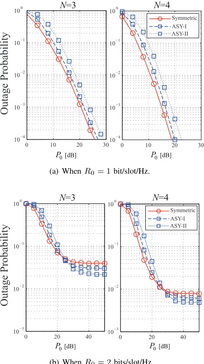
Fig. 3. Outage probabilities of VFD-MPRC under symmetric and asymmetric relay channels.
δs,i should be kept as big as possible, e.g.,τ δb,i≫δs,i
orτ δb,i≪δs,i. In other words, a lower error floor can be
achieved if the SIC decoding at the relays is facilitated;
• A lower error floor can be achieved with a smaller target data rateR0.
VI. SIMULATIONRESULTS
In this section, we demonstrate the performance of the proposed VFD-MPRC. Firstly, we evaluate the performance of VFD-MPRC with symmetric and asymmetric relay chan-nels. For the symmetric case, we assume that the relays are located close to each other at the middle of S and D, where
δs,i−1 = δs,r−1 = 0 dB and δi,d−1 = δ
−1
r,d = 0 dB ∀ i ∈ I. For
the asymmetric case, for ease of illustration, we consider a toy example where each relay Ri moves along the direct line
between S and D subject to a constraintδ−s,i1[dB]+δ−i,d1[dB]= 0
dB ∀ i∈ I. To isolate the effects of other parameters, we let
PS =PR=P0andδ−i,j1=δr,r−1= 10dB∀ i, j∈ I, i̸=j.
In Fig. 3, the outage performance of two asymmetric cases, denoted by ASY-I and ASY-II, are simulated and compared to that of the symmetric case. When there areN = 3relays, we have [δs,−11, δs,−12, δs,−31] = [5,−2,−5]dB and[δs,−11, δs,−21, δ−s,31] = [8,−4,−8] dB for ASY-I and ASY-II respectively. When
there are N = 4 relays, we have [δ−s,11, δs,−21, δ−s,13, δs,−14] = [5,3,−3,−5]dB and[δs,−11, δs,−21, δs,−31, δs,−41] = [8,5,−5,−8]dB for ASY-I and ASY-II respectively. That is, ASY-II is more asymmetric compared to ASY-I.
In Fig. 3(a), the outage probabilities are demonstrated when
R0= 1bit/slot/Hz. It is observed that the same diversity order ofN−1is achieved by both symmetric and asymmetric cases. While the symmetric case achieves the best performance, a worse performance is achieved for more asymmetric relay channels. A possible reason is that for those relays with asymmetric relay channels, if it has a stronger source-relay link, then its corresponding relay-destination link is relatively weak. Conversely, if it has a stronger relay-destination link, then the corresponding source-relay link is relatively weak. Whereas for the symmetric case, no such limit exists.
For better illustrations, the outage probabilities whenR0=
2 bits/slot/Hz are also demonstrated in Fig. 3(b). In the low
P0regime, it is observed that the symmetric case outperforms the asymmetric cases. This is reasonable as for those relays with asymmetric relay channels, a bottleneck exists either in the first hop or in the second hop. Whereas for the symmetric case where each relay has comparable source-relay and relay-destination links on average, there is a better chance that the source packet is successfully delivered to the destination. In the high P0 regime, conversely, a better performance is achieved by the more asymmetric case. This is reasonable due to the employment of SIC decoding in dealing with the IRI. With asymmetric relay channels, potentially there exists a more significant power difference between the desired signal and the IRI received at the relays. This is able to facilitate the SIC decoding and result in a lowerπ0, thus touching a lower error floor as given in (59).
A. Benchmark Cases
Next, we focus on the MPRC with symmetric relay channels and evaluate its performance in comparisons with the follow-ing two benchmark cases.
• HD-MPRC: a cooperative MPRC with N half-duplex relays, as shown in Fig. 1(a). For fair comparisons, the first half of a time slot is used for source transmission and the second half is used for relay transmission, as illustrated in Fig. 4(a);
• FD-MPRC: a cooperative MPRC with N full-duplex
relays that are able to receive and transmit signals si-multaneously with one slot processing delay. Similar to VFD-MPRC, an entire time slot is used for simultaneous source and relay transmissions, as illustrated in Fig. 4(b). For the benchmark case of FD-MPRC, two antennas are deployed at each intermediate relay Ri,i∈ Ifor simultaneous
transmission and reception, respectively. Then there exists a self-loop interference (SI) channel hi,i from the transmit antenna to the receive antenna of Ri [41]. Although various
. . .
Tx: S
Tx: Rb
. . .
Rx: D
L+1slots
. . .
x S(1) x S(1) x S(1)
x S(2) x S(2) x S(2)
x S(3) x S(3)
x S(3) x S(L+1)
x S(L+1) x S(L+1) (a) HD-MPRC.
. . .
Tx: STx: Rb
. . .
Rx: DL+1slots
. . .
x S(1)x S(1) x S(1) x S(2)
x S(2) x S(2)
x S(L)
[image:11.612.56.297.53.193.2]x S(L) x S(L) (b) VFD-MPRC.
Fig. 4. Transmitted and received signals in a data frame that consists of L+ 1time slots.
previously received packet xS(t−1), meanwhile it attempts to decode the currently transmitted source packetxS(t)that is
subject to the residual SI, and the restN−1relays attempt to decodexS(t)that is subject to an IRI from Rb. For comparison
purposes, the following conditions for the residual SI are considered [42].
• FD-MPRC-I: the effective SI channel hi,i experiences
flat fading that changes independently from slot to slot following a circularly symmetric complex Gaussian dis-tribution CN(0, δ−SI1)∀ i∈ I;
• FD-MPRC-II: there exists a residual SI component of
constant power PSI at relay Ri ∀ i∈ I, irrespective of
the SI channel condition and relay transmission power. This corresponds to an over-optimistic case.
• FD-MPRC-III: the SI component is perfectly cancelled
at the full-duplex relays. This corresponds to an ideal case and the corresponding performance provides a per-formance upper bound.
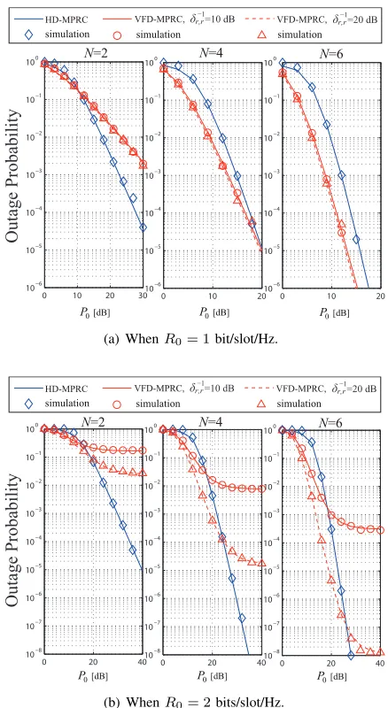
Unless otherwise specified, in the following we let δ−s,i1=
δs,r−1 = 0 dB, δi,d−1 =δr,d−1 = 0 dB and δi,j−1 =δ−r,r1 = 10 dB respectively∀i, j∈ I andi̸=j. As illustrated in Fig. 5–Fig. 8, we use lines to denote the analytical results derived in this paper and use markers to denote the Monte Carlo simulation results.
B. Error Floor and Diversity Order of VFD-MPRC
Firstly, we evaluate the outage performance of the proposed VFD-MPRC. As illustrated in Fig. 5, with an increase in P0, the outage performance of VFD-MPRC is improved. However, we cannot keep reducing the outage probability by increasing
P0, and an error floor is met in the highP0 regime. This is consistent with Lemma 1 that due to the existence of IRI that scales with the relay transmission power, the received signal-to-interference-plus-noise ratio (SINR) at each relay is limited to a finite value when PS, PR → ∞, as given in (16) and
(17). This limits the SIC decoding and there always exists a non-zero probability that a source packet can be decoded by none of the relays.
From Fig. 5(a), with more relays available, a lower error floor can be reached. From Fig. 5(b), a lower error floor can be reached with stronger inter-relay channels through which
0 5 10 15 20 25 30 35 40
10−4 10−3 10−2 10−1
100
O
ut
age
P
roba
bi
li
ty
P (31) Error floor(52)
out
P out(simulation)
N=4
N=6 N=2
P0 [dB]
(a) When R0 = 2 bits/slot/Hz and N = 2,4,6 respectively.
0 5 10 15 20 25 30 35 40
10−5 10−4
10−3 10−2 10−1 100
O
ut
age
P
roba
bi
li
ty
P (31)
Error floor(52) out
P out(simulation)
r,r
−1
δ =0 dB
r,r
−1
δ =10 dB
r,r−1 δ =20 dB
P0 [dB]
(b) WhenR0= 2bits/slot/Hz,N= 4andδ− 1
r,r= 0dB,
10dB,20dB respectively.
0 5 10 15 20 25 30 35 40
10−6 10−5 10−4
10−3 10−2 10−1 100
O
ut
age
P
roba
bi
li
ty
P (31)
Error floor(52)
out
P out(simulation) R 0=3
R 0=2
R 0=1
R 0=0.5
R 0=0.8
P0 [dB]
[image:11.612.346.527.416.555.2](c) WhenN = 4andR0= 0.5,0.8,1,2,3bits/slot/Hz respectively.
Fig. 5. Outage probability of VFD-MPRC and the corresponding error floor in the highP0regime.
0 5 10 15 20 25 30 35 40 10−6
10−5 10−4 10−3 10−2 10−1 100
N=4
O
ut
age
P
roba
bi
li
ty
N=6
P [dB] 0
N=2
N=3
N=5
P out(31)R
P out(31), R 0.8
0
0
P out(simulation)R0
[image:12.612.328.547.49.449.2]P out(simulation)R0 0.8
Fig. 6. Outage probability of the proposed VFD-MPRC whenR0= 0.8,1 bits/slot/Hz andN= 2,3,4,5,6respectively.
scenarios, e.g., R0>1, whereas no such bottleneck exists for low rate scenarios, e.g., R0≤1. The above observations also validate Lemma 2 that although an error floor is inevitable for relatively high rate scenarios, the error floor can be debased by proper parameter designs thus achieving favorable system outage performance.
In order to better illustrate the diversity order of VFD-MPRC when R0 ≤1, the outage performance with different numbers of relays is demonstrated in Fig. 6 whenR0= 0.8,1 bits/slot/Hz respectively. It is observed that with more relays available, a higher diversity order can be achieved. To be specific, with N relays, a diversity order of N −1 can be achieved asymptotically in the high SNR regime. The reason why full diversity order cannot be achieved is that when the selected best relay Rbforwards the previously received source
packet, only the remaining N −1 relays attempt to decode the current source packet. Since the source information can be delivered through at mostN−1independent paths, a diversity order of N −1 is achieved asymptotically [7]. On the other hand, with a lower target rate, i.e., R0 = 0.8 bits/slot/Hz, it is observed that a better outage performance is achieved than the case where R0 = 1 bit/slot/Hz while the same diversity order is achieved.
C. VFD-MPRC vs HD-MPRC
Next we compare the outage performance of the proposed VFD-MPRC to that of HD-MPRC in Fig. 7. As illustrated in Fig. 7(a), the outage probabilities are demonstrated when
R0 = 1 bit/slot/Hz. When there are N = 2 relays, it is observed that VFD-MPRC performs better whenP0≤10dB, whereas HD-MPRC performs better when P0 >10 dB. This is reasonable as a higher diversity order is achieved for HD-MPRC than VFD-HD-MPRC, thus HD-HD-MPRC performs better in the high P0 regime where the diversity order dominates the outage performance. With more relays available, e.g., N = 4,6, it is observed that significant performance improvements can be achieved by VFD-MPRC over HD-MPRC in both low and modest P0 regimes. This is reasonable as although
0 10 20 30
10−6 10−5 10−4 10−3 10−2 10−1 100
0 10 20
10−6 10−5 10−4 10−3 10−2 10−1 100
0 10 20
10−6 10−5 10−4 10−3 10−2 10−1 100
N=2 N=4 N=6
O
ut
age
P
roba
bi
li
ty
HD-MPRC VFD-MPRC, r,r
−1
δ =10 dB r,r
−1 δ =20 dB VFD-MPRC, simulation simulation simulation
P [dB]0 P [dB]0 P [dB]0
(a) WhenR0= 1bit/slot/Hz.
0 20 40 10−8
10−7 10−6 10−5 10−4 10−3 10−2 10−1 100
0 20 40 10−8
10−7 10−6 10−5 10−4 10−3
10−2 10−1 100
0 20 40 10−8
10−7 10−6 10−5 10−4 10−3 10−2 10−1
100 N=2 N=4 N=6
O
ut
age
P
roba
bi
li
ty
HD-MPRC VFD-MPRC, r,r −1
δ =10 dB VFD-MPRC,δ r,r−1=20 dB simulation simulation simulation
P [dB]0 P [dB]0 P [dB]0
(b) WhenR0= 2bits/slot/Hz.
Fig. 7. Outage probabilities of VFD-MPRC and HD-MPRC with a group ofN intermediate relays.
a lower diversity order is achieved by the proposed VFD-MPRC asymptotically, it achieves a pre-log factor approaching 1. Whereas there is a pre-log factor 12 in the conventional HD-MPRC, thus it can bring its advantage into play only in the very highP0 regime. Then the proposed VFD-MPRC is able to provide a higher achievable rate than that of the HD-MPRC, which results in a lower outage probability in both low and modest SNR regimes. On the other hand, it is observed that with stronger inter-relay channels, i.e.,δ−r,r1= 20dB, since the SIC decoding at relays is facilitated, a slightly better outage performance is achieved for VFD-MPRC.
Fig. 7(b) displays the outage probabilities of VFD-MPRC and HD-MPRC when R0 = 2 bits/slot/Hz. It is observed that while a full diversity order is achieved by HD-MPRC, no diversity gains are available in VFD-MPRC that always experiences an error floor with an increase in P0. When
[image:12.612.61.288.52.232.2]0 20 40 10−6
10−5 10−4 10−3 10−2 10−1 100
0 10 20 30
10−6 10−5 10−4 10−3 10−2 10−1 100
0 10 20
10−6 10−5 10−4 10−3 10−2 10−1 100
O
ut
age
P
roba
bi
li
ty
P0 [dB] P0 [dB] P0 [dB]
VFD−MPRC FD-MPRC-I FD-MPRC-II FD-MPRC-III simulation simulation simulation simulation
N=2 N=4 N=6
(a) WhenR0= 1bit/slot/Hz.
0 20 40
10−6 10−5 10−4 10−3 10−2 10−1 100
0 20 40
10−6 10−5 10−4 10−3 10−2 10−1 100
0 20 40
10−6 10−5 10−4 10−3 10−2 10−1 100
O
ut
age
P
roba
bi
li
ty
VFD−MPRC FD-MPRC-I FD-MPRC-II FD-MPRC-III simulation simulation simulation simulation
P0 [dB] P0 [dB] P0 [dB]
N=2 N=4 N=6
[image:13.612.66.284.54.452.2](b) WhenR0= 2bits/slot/Hz.
Fig. 8. Outage probabilities of VFD-MPRC and FD-MPRC with a group of N intermediate relays.
proposed VFD-MPREC is able to support a higher achievable rate, thus achieving performance improvements over HD-MPRC in both low and modest P0 regimes. Whereas in the high P0 regime, the diversity loss due to the IRI and SIC decoding at the relays severely limits the performance of VFD-MPRC. On the other hand, with stronger inter-relay channels, i.e., δ−1
r,r = 20 dB, it is observed that the SIC decoding at
relays is facilitated thus significantly improving the outage performance of VFD-MPRC.
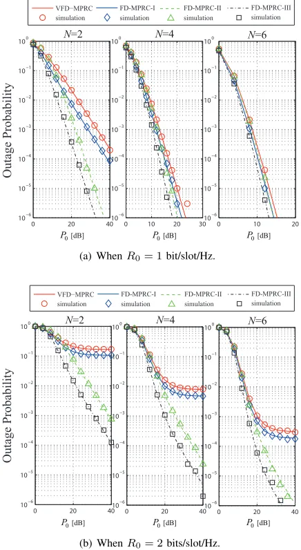
D. VFD-MPRC vs FD-MPRC
Next we compare the outage performance of the proposed VFD-MPRC to that of the FD-MPRC with a group ofN full-duplex relays in Fig. 8. As illustrated in Fig. 8(a), the outage probabilities are demonstrated when R0 = 1 bit/slot/Hz, and different conditions of the residual SI in FD-MPRC are considered. It is observed that comparable performances are achieved by the proposed VFD-MPRC and FD-MPRC. For FD-MPRC-I, we consider a fading SI channel between the well isolated transmit and receive antennas, e.g., δ−SI1=−10
dB. Since the residual SI scales with the relay transmission power, it is observed that a same diversity order of N−1 is achieved by FD-MPRC-I as the proposed VFD-MPRC with an increase inP0. For FD-MPRC-II where there is a residual SI component of fixed powerPSI = 10dB irrespective of the relay transmission power, it is observed that a full diversity order of N is achieved asymptotically. This is reasonable as besides the rest N −1 relays, the selected best relay is able to forward the previous packet while decoding the currently transmitted source packet also. Whereas in the proposed VFD-MPRC, since the selected best relay cannot transmit and receive simultaneously, a diversity order ofN−1is achieved asymptotically. For the ideal case where the SI is perfectly cancelled, the best performance is achieved by FD-MPRC-III, which again, achieves a full diversity order of 2. With more relays available, e.g.,N = 4,6, it is observed that a reasonably good performance is achieved by the proposed VFD-MPRC compared to FD-MPRC.
For better illustrations, we also demonstrate the outage probabilities of the proposed VFD-MPRC and FD-MPRC whenR0= 2bits/slot/Hz in Fig. 8(b). Similarly, a comparable performance to FD-MPRC is achieved by VFD-MPRC. With a fading SI channel whereδ−SI1=−10dB, the outage probability of FD-MPRC-I experiences an error floor and no diversity gains can be achieved. This is reasonable as for the selected best relay, the SI increases linearly with the relay transmission power. Whereas for the restN−1relays, the desired signal is subject to comparable IRI that limits the SIC decoding. With only a constant-power SI component wherePSI = 10dB, it is observed that a diversity order of1is achieved by FD-MPRC-II. Again, the best performance is achieved by FD-MPRC-III where the SI is perfectly cancelled, and a diversity order of1is achieved. Whereas for the proposed VFD-MPRC, no diversity gains are available any more due to a bottleneck brought by SIC that is limited by the comparable IRI.
Remark 4: From the above comparisons and observations,
a close-to-full diversity order can be exploited by the proposed VFD-MPRC in low rate scenarios where R0 ≤ 1, while significantly recovering the spectrum efficiency loss in HD-MPRC. On the other hand, in relatively high rate scenarios whereR0>1, although no diversity gains are available due to the IRI, performance improvements can be achieved by VFD-MPRC in both low and modest SNR regimes over the conventional HD-MPRC. Furthermore, with only half-duplex relays, a comparable performance can be achieved by the proposed VFD-MPRC to its full-duplex counterpart.
VII. CONCLUSIONS
were analyzed and derived in closed-form expressions. By comparisons with existing half/full-duplex relay systems, our results demonstrate the advantages of the proposed approach in low rate scenarios, where a close-to-full diversity order is achieved while achieving a comparable spectrum efficiency to the full-duplex relay system. In high rate scenarios, the system is interference-limited as similar to a full-duplex relay system with self-loop interference channel. Even though, performance gains can be achieved over conventional half-duplex relay systems in low and/or modest SNR regimes.
An interesting extension of our work in future is that for those relays that successfully decode the source packet but are not selected, they can store the decoded data in buffer, which can be used for self-interference cancellation in the subsequent time slot. Intuitively, this is able to further mitigate the IRI thus enhancing the decoding performance of the relays.
REFERENCES
[1] Q. Li, M. Yu, A. Pandharipande, and X. Ge, “Outage analysis of cooperative multi-path relay channels with virtual full-duplex relaying,” IEEE International Conference on Communication Workshop (ICCW 2015),pp. 925–930, London, UK, June 2015.
[2] J. N. Laneman, D. N. C. Tse, and G. W. Wornell, “Cooperative diversity in wireless networks: efficient protocols and outage behavior,”IEEE Trans. Inf. Theory,vol. 50, no. 12, pp. 3062–3080, Dec. 2004.
[3] G. Kramer, M. Gastpar, and P. Gupta, “Cooperative strategies and capacity theorems for relay networks,”IEEE Trans. Inf. Theory,vol. 51, no. 9, pp. 3037–3063, Sept. 2005.
[4] Q. Li, R. Q. Hu, Y. Qian, and G. Wu, “Cooperative communications for wireless networks: techniques and applications in lte-advanced systems,” IEEE Wireless Commun.,vol. 19, no. 2, pp. 22–29, Apr. 2012. [5] V. K. Sakarellos, D. Skraparlis, A. D. Panagopoulos, and J. D.
Kanel-lopoulos, “Cooperative diversity performance in millimeter wave radio systems,”IEEE Trans. Commun.,vol. 60, no. 12, pp. 3641–3649, Dec. 2012.
[6] R. Zhang, et al., “Advances in base- and mobile-station aided cooperative wireless communications: an overview,”IEEE Veh. Tech. Mag.,vol. 8, no. 1, pp. 57–69, Mar. 2013.
[7] A. Bletsas, A. Khisti, D. Reed, and A. Lippman, “A simple cooperative diversity method based on network path selection,”IEEE J. Sel. Areas Commun.,vol. 24, no. 3, pp. 659–672, Mar. 2006.
[8] A. Adinoyi, Y. Fan, H. Yanikomeroglu, H. V. Poor, and F. AI-Shaalan, “Performance of selection relaying and cooperative diversity,” IEEE Trans. Wireless Commun.,vol. 8, no. 12, pp. 5790–5795, Dec. 2009. [9] Y. Jing and H. Jafarkhani, “Single and multiple relay selection schemes
and their achievable diversity orders,”IEEE Trans. Wireless Commun., vol. 8, no. 3, pp. 1414–1423, Mar. 2009.
[10] A. Bletsas, H. Shin, and M. Z. Win, “Cooperative communications with outage-optimal opportunistic relaying,”IEEE Trans. Wireless Commun., vol. 6, no. 9, pp. 3450–3460, Sept. 2007.
[11] H. Moharrer and A. Olfat, “Joint relay selection and cooperative beamforming in two-hop multi-relay decode-and-forward networks,”IET Commun.,vol. 8, no. 18, pp. 3245–3253, Aug. 2014.
[12] S. S. Ikki and M. H. Ahmed, “Performance analysis of adaptive decode-and-forward cooperative diversity networks with best-relay selection,” IEEE Trans. Commun.,vol. 58, no. 1, pp. 68–72, Jan. 2010.
[13] X. Chen, Y. Xu, and D. Zhang, “Outage performance analysis and optimal power allocation of opportunistic cooperation communications without direct-link,”IEEE WCSP,pp. 1–4, Nanjing, China, Sept. 2011. [14] I.-H. Lee, H. Lee, and H.-H. Choi, “Exact outage probability of relay
selection in decode-and-forward based cooperative multicast systems,” IEEE Commun. Letters,vol. 17, no. 3, pp. 483–486, Mar. 2013. [15] M. Ju, K.-S. Hwang, and H.-K. Song, “Relay selection of cooperative
diversity networks with interference-limited destination,” IEEE Trans. Veh. Tech.,vol. 62, no. 9, pp. 4658–4665, Nov. 2013.
[16] Y. Hu, K. H. Li, and K. C. Teh, “An efficient successive relaying protocol for multiple-relay cooperative networks,”IEEE Trans. Wireless Commun., vol. 11, no. 5, pp. 1892–1899, May 2012.
[17] I. Krikidis, H. A. Suraweera, P. J. Smith, and C. Yuen, “Full-duplex relay selection for amplify-and-forward cooperative networks,” IEEE Trans. Wireless Commun.,vol. 11, no. 12, pp. 4381–4398, Dec. 2012.
[18] M. Eddaghel, U. Mannai, G. Chen, and J. Chambers, “Outage probability analysis of an amplify-and-forward cooperative communication system with multi-path channels and max-min relay selection,”IET Commun., vol. 7, no. 5, pp. 408-416, Mar. 2013.
[19] Z. Zhou, S. Zhou, J.-H. Cui, and S. Cui, “Energy-efficient cooperative communication based on power control and selective single-relay in wireless sensor networks,”IEEE Trans. commun.,vol. 7, no. 8, pp. 3066– 3078, Aug. 2008.
[20] W.-J. Huang, Y.-W. P. Hong, and C.-C. J. Kuo, “Lifetime maximization for amplify-and-forward cooperative networks,” IEEE Trans. Commun., vol. 7, no. 5, pp. 1800–1805, May 2008.
[21] S. A. Mousavifar and C. Leung, “Lifetime analysis of a two-hop amplify-and-forward opportunistic wireless relay network,”IEEE Trans. commun., vol. 12, no. 3, pp. 1186–1195, Mar. 2013.
[22] B. Rankov and A. Wittneben, “Spectral efficient protocols for half-duplex fading relay channels,” IEEE J. Sel. Areas Commun., vol. 25, no. 2, pp. 379–389, Feb. 2007.
[23] Q. Li, S. H. Ting, A. Pandharipande, and Y. Han, “Adaptive two-way relaying and outage analysis,”IEEE Trans. Wireless Commun.,vol. 8, no. 6, pp. 3288–3299, Jun. 2009.
[24] Q. You, Y. Li and Z. Chen, “Joint relay selection and network coding for error-prone two-way decode-and-forward relay networks,”IEEE Trans. Commun.,vol. 62, no. 10, pp. 3420–3433, Oct. 2014.
[25] S. Atapattu, Y. Jing, H. Jiang, and C. Tellambura, “Relay selection schemes and performance analysis approximations for two-way net-works,”IEEE Trans. Commun.,vol. 61, no. 3, pp. 987–998, Mar. 2013. [26] K.-S. Hwang, M. Ju, and M.-S. Alouini, “Outage performance of op-portunistic two-way amplify-and-forward relaying with outdated channel state information,”IEEE Trans. Commun.,vol. 61, no. 9, pp. 3635–3643, Sept. 2013.
[27] N. Zlatanov, R. Schober, and P. Popovski, “Buffer-aided relaying with adaptive link selection,”IEEE J. Sel. Areas Commun.,vol. 31, no. 8, pp. 1530–1542, Aug. 2013.
[28] A. Ikhlef, J. Kim, and R. Schober, “Mimicking full-duplex relaying using half-duplex relays with buffers,”IEEE Trans. Veh. Tech.,vol. 61, no. 7, pp. 3025–3037, Sept. 2012.
[29] A. Ikhlef, D. S. Michalopoulos, and R. Schober, “Max-max relay selection for relays with buffers,” IEEE Trans. Wireless Commun., vol 11, no. 3, pp. 1124–1135, Mar. 2012.
[30] I. Krikidis, T. Charalambous, and J. S. Thompson, “Buffer-aided relay selection for cooperative diversity systems without delay constraints,” IEEE Trans. Wireless Commun., vol. 11, no. 5, pp. 1957–1967, May. 2012.
[31] S. M. Kim and M. Bengtsson, “Virtual full-duplex buffer-aided relaying — relay selection and beamforming,” IEEE PIMRC, pp. 1748–1752, London, UK, Sept. 2013.
[32] S. M. Kim and M. Bengtsson, “Virtual full-duplex buffer-aided relaying in the presence of inter-relay interference,” arXiv:1501.07319v2, Jul. 2015.
[33] T. Riihonen, S. Werner, and R. Wichman, “Hybrid full-duplex/half-duplex relaying with transmission power adaptation,”IEEE Trans. Wire-less Commun.,vol. 10, no. 9, Sept. 2011.
[34] Q. Li, A. Pandharipande, and X. Ge, “Cognitive spectrum sharing with bi-directional secondary system,” CROWNCOM 2014, Oulu, Finland, June 2014, pp. 13–18.
[35] Q. Li, M. Yu, A. Pandharipande, T. Han, J. Zhang, and X. Ge, “Co-operative two-path relay channels: performance analysis using a markov framework,” IEEE International Conference on Communications (ICC 2015),pp. 3573–3578, London, UK, June 2015.
[36] A. Papoulis and S. U. Pillai,Probability, Random Variables and Stochas-tic Processes.4th Edition. McGraw Hill, 2002.
[37] T. M. Cover and J. A. Thomas,Elements of Information Theory. 2nd edition. Wiley, 2006.
[38] J. G. Proakis,Digital communications.4th edition. McGraw-Hill, 2001. [39] M. Morelli and U. Mengali, “A comparison of pilot-aided channel estimation methods for OFDM systems,”IEEE Trans. Signal Processing, vol. 49, no. 12, pp. 3065–3073, Dec. 2012.
[40] L. Zheng and D. N. C. Tse, “Diversity and multiplexing: a fundamental tradeoff in multiple-antenna channels,”IEEE Trans. Inf. Theory,vol. 49, no. 5, pp. 1073–1096, May 2003.