Nonlinear Control of Single-Phase PWM Rectifiers
with Inherent Current-Limiting Capability
George C. Konstantopoulos,
Member, IEEE,
and Qing-Chang Zhong,
Senior Member, IEEE
Abstract—In this paper, a nonlinear controller with a
current-limiting property is proposed to guarantee accurate dc output voltage regulation and unity power factor operation for single-phase PWM rectifiers without the need of a single-phase-locked-loop (PLL). The proposed current-limiting controller is fully indepen-dent of the system parameters and can guarantee asymptotic stability and convergence to a unique solution for the closed-loop system using nonlinear control theory. Without requiring the instantaneous measurement of the grid voltage, a PLL, an external limiter or a saturation unit, the proposed strategy guarantees that the input current of the rectifier will always remain below a given value. An analytic framework for selecting the controller parameters is also presented to provide a complete controller design procedure and it is also proven that the current-limiting property is maintained even when the grid voltage drops. Extensive experimental results are presented to verify the proposed controller when the load changes, the reference dc output voltage changes and the grid voltage drops.
Index Terms—PWM rectifiers, nonlinear control, current limit,
asymptotic stability, grid voltage dip
I. INTRODUCTION
A
C/DC power converters are widely used in power systemsto integrate loads or power sources to the electric grid by operating as a rectifier or an inverter, respectively [1], [2], [3], [4]. Depending on the application, ac/dc converters can be single-phase or three-phase with main tasks the accurate dc bus voltage regulation and power factor correction (PFC). For rectifiers, the PFC can be achieved by controlling the input current to be in phase with the input voltage and has been extensively studied in the literature [5], [6], [7], [8], [9], [10], [11], [12].AC/DC converters are inherently nonlinear systems due to their switching operating function. Among these devices, the single-phase full-bridge or H-bridge rectifier represents a common PFC converter operating in pulse-width-modulating (PWM) mode and its model can be generalized in the three-phase converter case [9], [13], [14], [15], [16]. Therefore, sev-eral researchers have developed control strategies for single-phase rectifiers to achieve both dc output voltage regulation
G. C. Konstantopoulos is with the Department of Automatic Con-trol and Systems Engineering, The University of Sheffield, Sheffield, S1 3JD, UK, tel: +44-114 22 25637, fax: +44-114 22 25683 (e-mail: [email protected]).
Q.-C. Zhong is with the Department of Electrical and Computer Engineering, Illinois Institute of Technology, Chicago, IL 60616, USA, and also with the Department of Automatic Control and Systems Engineering, The University of Sheffield, Sheffield, S1 3JD, UK (e-mail: [email protected]).
The financial support from the EPSRC, UK under Grant No. EP/J01558X/1 is greatly appreciated.
Some preliminary results were presented at the 2015 American Control Conference, Chicago, IL, 1-3 July 2015.
Corresponding author: Dr G. C. Konstantopoulos
and unity power factor operation. The most commonly used method includes a cascaded structure where an outer loop is used to control the dc output voltage and an inner current loop is used to control the input current to be in phase with the input voltage. In the traditional control methods, a Proportional-Integral (PI) controller is included into the outer loop and the inner current controller usually consists of a hysteresis current method [5], [17], [18], [19]. Additionally, the cascaded control structure can be combined with intelligent techniques such as fuzzy control to incorporate a sensorless design, as described in [20]. The traditional control methods have a simple structure and are effective in practice but they lack from a rigorous stability theory for the complete closed-loop system. Although for rectifier applications, boost-type PFC rectifier can be used instead of full-bridge rectifiers [21], the efficiency of these converters is significantly reduced and they result in higher power losses, especially for high-power applications [22].
Due to the nonlinear dynamic model of the converter, which can be obtained using the average analysis [23], [24], passivity-based control represents a powerful tool and can be effectively applied to achieve both control tasks and guarantee global asymptotic stability of the closed-loop system [7], [12], [15]. Since the accurate knowledge of the load is required in this case, adaptive passivity-based structures have been developed to cope with the load uncertainty [25], [26], [12]. However, the control scheme still depends on the rest of the system parameters, i.e. the inductor, the capacitor and the measurement of the grid voltage. These parameters might not be accurately known a priori or might change during the system operation. Furthermore, more complicated loads can be connected at the rectifier output, (e.g. nonlinear, power converter-fed loads), which will increase the complexity of the model and consequently the controller design.
also inherit a switching behavior between the normal operation and the current-limiting operation when the grid voltage drops [36], [39]. However, the use of saturation units can lead to undesired oscillations in several applications and asymptotic stability cannot be guaranteed, mainly due to integrator windup [32], [38]. Although anti-windup techniques can be inserted into the control design, traditional anti-windup methods lack from a rigorous stability analysis and modern anti-windup methods require the knowledge of the plant to guarantee stability [40], [41], [42]. Hence, it is a challenge to design a parameter-free controller with a simple and unified structure (no switching between control algorithms) that guarantees nonlinear stability of the closed-loop system and a given limit for the input current even under grid voltage sags.
In this paper, the single-phase full-bridge rectifier is inves-tigated and a nonlinear controller that achieves accurate dc output voltage regulation, unity power factor operation and closed-loop stability with a limited input current, is developed. The proposed current-limiting nonlinear controller is fully independent of the system parameters, has a simple structure that leads to an easy implementation and achieves PFC at the input of the rectifier, which practically corresponds to PFC for the complete system. Using nonlinear Lyapunov theory, the controller operation is investigated and based on the input-to-state stability theory [43], closed-loop system stability in the sense of boundedness and eventually asymptotic convergence to a desired solution are proven. Particularly, for a given maximum RMS valueImaxof the input current, the controller parameters can be suitably selected to guarantee that the input current will always remain bounded below this given value. This imposes a significant advantage compared to the existing parameter-free control techniques, since the current-limiting function is embedded into the original control structure, no external limiters or switching operation are required, leading to a continuous-time controller with the same dynamics that allows the investigation of stability. Moreover, only an initial estimation of the RMS value of the grid voltage (which is known in practice) is required, while the instantaneous measurement of the grid voltage or an additional PLL are not needed, thus further simplifying the controller implementation. The current-limiting capability is guaranteed even in the cases where the input voltage varies or rapidly drops, extending the proposed controller performance to both normal and abnor-mal operations of the grid, i.e. during grid faults. Extensive experimental results are provided for the single-phase full-bridge rectifier to illustrate the proposed approach and verify its current-limiting capability under load changes, reference dc output voltage changes and input voltage sags.
The paper is organized as follows: In Section II, the dynamic model of the rectifier is obtained and the main problem addressed in this paper is formulated. In Section III, the current-limiting controller is proposed and analyzed. Closed-loop system stability is proven, an analytic framework for selecting the controller parameters is presented and the controller performance is extended to the cases of input voltage variations. In Section IV, experimental results are provided to verify the proposed controller performance and finally, in Section V, some conclusions are drawn.
L i +
-u
u u
u +
-vs
r L
i
[image:2.595.315.560.104.188.2]v C Vdc RL
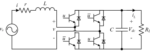
Figure 1. Single-phase full-bridge rectifier
II. PROBLEM FORMULATION
Consider a single-phase full-bridge rectifier feeding a re-sistive load as shown in Fig. 1. The converter consists of a boosting filter inductorL with a small parasitic resistance r, a dc capacitorC and 4 switches, whose switching signals are obtained from a PWM circuit taking values in the finite set
{−1,1}. Although the filter can be of different types (e.g.
LCL) to achieve better harmonic attenuation for the grid current, here anLfilter is considered for simplicity, since as it is explained below, at this stage, the current-limiting property and the stability are the main goals in this paper and not the power quality improvement. Parameter RL represents the load resistance,iis the inductor current,Vdcis the dc output voltage, v is the converter input voltage andvs is the single-phase grid voltage of the formvs=
√
2Vssinωt, whereVs is the RMS grid voltage andω is the grid angular frequency.
Using average model analysis [44], the nonlinear dynamic model of the system can be obtained using the Kirchhoff laws and the power equivalence of the converter as:
Ldi
dt = −ri−uVdc+vs (1)
CdVdc
dt = ui−
Vdc
RL
, (2)
where the control input u = v
Vdc represents the continuous-time duty-ratio signal of the rectifier bounded in the range [−1,1], which is fed to the PWM generator to result in the discrete signals of the switching elements, while the grid voltagevs represents an external uncontrolled input.
For system (1)-(2), the main tasks are to achieve accurate dc output voltage regulation and unity power factor operation. The average value of the dc output voltage V¯dc should be always regulated at a given reference value Vdcref. The value ofV¯dc can be obtained fromVdcwith a low-pass filter which rejects the second-order harmonics. In practice, the average value of the dc output voltage is calculated using a low-pass filter forV2
dcand then taking the square root of the result [45]. For the unity power factor operation, the currentishould be in phase with the grid voltagevs. In many applications of ac/dc converters (in the rectifier or inverter mode), power factor is also considered at the input of the converter [1], i.e., the current
i to be in phase with the converter voltage v, since in most cases the filter inductor does not cause a significant phase shifting between the two voltages vsandv.
depend on the system parameters and the load dynamics, in this paper, the existence of a control structure for rectifiers is investigated that achieves both tasks and incorporates all of the following properties:
1) Complete independence from the system and load pa-rameters;
2) Nonlinear closed-loop system stability with a given current limit;
3) Simple structure, based on the dynamics and the sensors required for the implementation.
III. PROPOSED CONTROLLER DESIGN AND STABILITY ANALYSIS
A. Current-limiting nonlinear controller
Taking into account all of the controller properties men-tioned in the previous section, the following current-limiting nonlinear controller is proposed:
u(t) = Vv(t) dc(t)=
w(t)i(t)
Vdc(t)
, (3)
wherewrepresents a virtual resistance which changes accord-ing to the nonlinear dynamic equations
˙
w=cV¯dc−Vdcref
wq2 (4)
˙
wq=−
c(w−wm)wq ∆w2
max
¯
Vdc−Vdcref
−k (w−wm) 2 ∆w2
max
+w2q−1
!
wq,
(5)
with c, k, wm,∆wmax being positive constants. Note that for the implementation of (3), the current i should be the average value (sinusoidal) of the actual inductor current and can be obtained using a low-pass filter that rejects the higher harmonics (switching ripples), whileVdcrepresents the actual output voltage which includes the second-order harmonics.
From the controller structure, it becomes clear that the pro-posed controller is fully independent of the system parameters and does not require the instantaneous measurement of the grid voltagevsor a PLL. When the average dc output voltageV¯dc is regulated at the reference value Vdcref, then the controller parameterwis regulated at a constant valuewe, sincew˙ = 0 from (4), and consequently (3) becomes
v(t) =we·i(t) (6)
which shows that the input voltage of the converter v is in phase with the current i and therefore unity power factor is achieved. As a result, both control tasks of the converter can be accomplished. In order to investigate whether this operation is possible, the controller dynamics are further analyzed.
For system (4)-(5), consider the Lyapunov function
W = (w−wm) 2 ∆w2
m
+w2
q. (7)
Its time derivative becomes
˙
W =−2k (w−wm)
2 ∆w2
m
+wq2−1
!
w2q. (8)
Therefore, if the initial conditions are chosen w0 =wm and
wq0 = 1, then W˙ (t) = 0 ⇒ W(t) = W(0) = 1,∀t ≥ 0 implying thatwandwq start and stay thereafter on the ellipse
W0:
W0=
(
w, wq ∈R:
(w−wm)2 ∆w2
m
+w2q = 1
)
, (9)
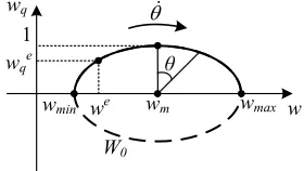
as shown in Fig. 2, which means that w ∈[wmin, wmax] = [wm−∆wm, wm+ ∆wm]. Note that the same operation is obtained for any initial conditionsw0 andwq0defined on the ellipseW0, i.e. satisfying
(w0−wm)2 ∆w2
m
+w2
q0= 1, (10) withwq0>0. Hence, one can chose accordingly the parame-terswm and∆wm in order forwmin>0at all times, i.e., it should be
wm>∆wm>0, (11)
which leads to w(t) > 0,∀t ≥ 0 and makes sense since it represents a virtual resistance in a rectifier application. The given bounds for the state w are important for limiting the current under a given maximum value as it will be analytically explained in the stability analysis described in Subsection III-B.
1
W0
wq
w wmax
we wqe
θɺ
wm
wmin
[image:3.595.367.507.416.495.2]θ
Figure 2. Controller states operation on ellipseW0
When the controller states operate on the ellipse W0, the controller dynamics (4)-(5) become
˙
w = cV¯dc−Vdcref
wq2 (12)
˙
wq = −
c(w−wm)wq ∆w2
max
¯
Vdc−V ref dc
. (13)
For system (12)-(13), consider the following transformation
w−wm = ∆wmsinθ (14)
wq = cosθ (15)
which results after some simple calculations that
˙
θ=
cwq
¯
Vdc−Vdcref
∆wm
. (16)
Expression (16) shows that the controller stateswandwq will move on the ellipseW0 with angular velocity given by (16). Therefore, if V¯dc → Vref
dc , then θ˙ → 0 and both controller states will stop moving and converge to their steady-state valuesweandwe
the transient response, the angular velocity will change sign and the states will oscillate around the equilibrium point.
Additionally, the controller states will move exclusively on the upper semi-ellipse of W0 (Fig. 2), for initial conditions w0 andwq0>0that satisfy (10). The reason is that ifwand wq try to reach the horizontal axis, then wq → 0 and as a result from (16), θ˙ →0 which forces the controller states to slow down independently from the differenceV¯dc−Vdcref. This fact prohibits the existence of an oscillating behavior (limit cycle) for the controller dynamics themselves, i.e., they will never continuously travel around the ellipse W0. In addition, since wq → 0 results in w˙ → 0 in (4), this means that the integration slows down near the limits, i.e. when w→wmin or w → wmax, and hence the proposed controller does not suffer from integrator windup issues. It should be mentioned that instead of the control dynamics (4)-(5) one can implement the proposed controller using (14), (15) and (16), and result in the same behavior since the two representations are equivalent.
B. Closed-loop system stability
From the previous analysis, it is clear that the proposed controller is able to achieve both precise output voltage regu-lation and unity power factor. However, in order to accomplish both tasks, closed-loop system stability should be guaranteed at all times. Sincewm>∆wm>0 andw0,wq0satisfy (10), then w and wq are bounded with w∈ [wmin, wmax], where
wmin>0. By substituting (3) into the original system (1)-(2), it yields
Ldi
dt = −(r+w)i+vs (17)
CdVdc
dt =
wi2 Vdc −
Vdc
RL
(18)
which is still a nonlinear system but (17) can be investigated as a time-varying system with w∈[wmin, wmax], where wmin,
wmax>0.
Now, for system (17), consider the Lyapunov function
V = 1
2Li
2 (19)
with time derivative ˙
V =−(r+w)i2+vsi
≤ −(r+wmin)i2+vsi <0, ∀ |i|> |
vs|
r+wmin (20)
which proves that system (17) is input-to-state stable (ISS) [43] and since the grid voltage is assumed to have a con-stant amplitude (stiff grid), then the inductor current will be bounded for allt≥0. Then, the remaining dynamics (18) can be written as
1 2C
dV2
dc
dt =−
V2
dc
RL
+wi2 (21)
which is a first-order differential equation of V2
dc with input
wi2. This system is bounded-input bounded-state stable and since w and i are proven to remain bounded, then V2
dc is bounded and consequently Vdc is bounded. Therefore, the closed-loop system solution
i(t) Vdc(t) w(t) wq(t)
T
will remain bounded for allt≥0.
Although the boundedness of the closed-loop system is proven by considering a single load resistorRL, it also holds true for any strictly dissipative load connected at the output of the rectifier with input Vdc and output the load current
iL, suitably extending the proposed controller application to rectifiers with more complicated loads (e.g. nonlinear, power converter-fed loads [7]). Taking into account the parasitic elements of the converter, the proof directly follows since for a strictly dissipative load there exists Vl(q) ≥ 0 and
ψ(q) > 0, such that V˙l ≤ VdciL − ψ(q), where q =
iL q1 . . . qn−1
T
∈Rn is the load state vector [43]. As a result, a maximum bound for the rectifier and load states can be always guaranteed with the proposed strategy. However, in practice a very important issue for the rectifier operation is to guarantee a given limit for the input current below a certain value. Since i is an ac signal, it is required for its RMS valueI to remain below a given maximum value
Imax. This also corresponds to a maximum allowed power of the system given asPmax=VsImax(since unity power factor is achieved). According to (20) and taking into account that
vs=
√
2Vssinωt, it is proven that
|i| ≤ √
2Vs
r+wmin
,∀t≥0, (22)
if initially i(0) satisfies the above inequality, indicating that
i introduces an ultimate bound, since according to the ISS property, the derivative of the Lyapunov function (19) is negative outside of this area. Inequality (22) can be expressed using the RMS value of the current as
I≤r+Vws
min
, (23)
because (22) is satisfied for allt≥0. Since it is required that
I≤Imaxat all times, then the controller parameterwmin can be chosen as
wmin=
Vs
Imax −
r≈ Vs
Imax
, (24)
since the inductor resistanceris usually considered very small and can be neglected. As a result, by selectingwminaccording to (24), then I(t) < Imax,∀t ≥ 0. It should be mentioned that due to the neglected parasitic resistancer and the small phase shifting of the filter inductor, the actual current will be limited to a slightly lower value thanImax but as it is already analytically proven, it will be I(t)< Imax,∀t ≥0. Thus, in practice, a slightly larger Imax can be selected to determine
wmin in (24).
Hence, the proposed controller can achieve an inherent current-limiting property for the rectifier without additional limiters or switching the controller operation. The controller remains continuous-time and allows the investigation of sta-bility using nonlinear systems theory.
Now assume there exists a pair we, we q
for whichwe
∈
[wmin, wmax]corresponding toV¯dc=V ref
dc . Then the current equation becomes
Ldi
dt =−(r+w
e)i+v
which represents a linear resistive-inductive RL circuit with resistance r+we. For a given we >0, system (25) asymp-totically converges to a unique sinusoidal solution i(t), since the system has a negative pole (−r+we
L ) and the input vs is sinusoidal with a constant amplitude and frequency. Using the average values and the power equivalence between ac and dc sides, at the steady state there is
¯
Ve dc
2
RL
=we(Ie)2
where V¯e
dcis the steady-state value ofV¯dcandIeis the RMS value of the steady-state solutioni(t)of (25), which results in
¯
Vdce =I ep
RLwe. (26)
Hence, the steady-state value of the average dc output voltage ¯
Ve
dc is unique and according to the controller dynamics can only be Vdcref. SinceVdc(t)>0 (rectifier operation), then the solution Vdc(t)of the output voltage is also unique.
However, if (Vdcref) 2
RL > Pmax where Pmax =VsImax due to the unite power factor, i.e., ifVdcref is chosen very large or the load RL changes to a small value, there will not exist a feasible we inside the range [w
min, wmax] corresponding to the desired solution. In this case,wwill continuously decrease (since θ <˙ 0 from V¯dc−Vdcref <0 and (16)) until it reaches the minimum valuewmin and the input current will reach the maximum value Imax. Note that w →wmin corresponds to
wq → 0 which leads the angular velocity θ˙ → 0 according to (16). This means that V¯dc will reach a value V¯e
dc 6=V ref dc for which (V¯dce)
2
RL = Pmax holds true. Therefore, even if by mistake or due to unpredicted errors the reference valueVdcref increases above the maximum allowed value (corresponding to the maximum allowed powerPmax), the previous analysis still applies and the closed-loop system will guarantee the current-limiting property.
The above analysis implies that there always exists we ∈ [wmin, wmax] at the steady state, corresponding to a unique solution
i(t) Vdc(t) w(t) wq(t) T
for the closed-loop system. However, the physical limitations of the rectifier should be considered for achieving the current-limiting prop-erty. Since the rectifier represents a boost power electronic device, the dc output voltage introduces a minimum limit, which assuming sinusoidal PWM operation, results in √2Vs. By neglecting the parasitic resistance of the inductor and taking into account the power equivalence, it results in
Pmax = VsImax=
¯
V2
dc
RL ≥
2V2
s
RL
,
which defines the allowed range of the load resistance
RL≥
2Vs
Imax
. (27)
This is a limitation of the rectifier since for a smaller load resistance, the input current will increase since the current can flow through the diodes independently from the control design. By taking into consideration all of these properties, asymptotic convergence to a unique solution can be proven as shown below.
Particularly, if (27) is satisfied for the load, then the closed-loop system states are bounded and a current-limiting property
I < Imax is achieved. As explained in the previous analysis, in this case there exists we ∈ [w
min, wmax] corresponding to a unique solution of the closed-loop system. Since w and
wq operate exclusively on W0, i.e., given from (12)-(13), then for a sufficiently small c > 0 in the controller design, the closed-loop system can be investigated as a two time-scale system with slow dynamics (12)-(13) and fast dynamics (17)-(18) as described in [43]. The fast current and voltage dynamics (17)-(18) (with respect to the controller dynamics) are investigated using the frozen parameter w. As in the case of (25), the current dynamics asymptotically converge to a unique solution depending on the frozen parameter w. Since w is proven to remain bounded inside the given range
w ∈ [wmin, wmax], then asymptotic stability of the solution
i(t, w) holds uniformly in w, which is sinusoidal since the system represents a typicalRLcircuit with positive resistance
r+w(see equation (25)). Consequently, the voltage dynamics (21) asymptotically converge to a solutionVdc(t, w)uniformly in the frozen parameterw since it can be viewed as a linear system with state V2
dc, input wi2, which has a negative real pole, i.e.− 2
CRL. Then, taking into account (26), it yields
¯
Vdc(w) =Ie(w)
p
RLw. (28)
As a result, (28) introduces the boundary layer of the system. In this way, the slow controller dynamics (12)-(13) become
˙
w = cIe(w)p
RLw−Vdcref
w2q (29)
˙
wq = −
c(w−wm)wq ∆w2
max
Ie(w)p
RLw−Vdcref
,(30)
This represents a stable second-order autonomous system in the sense of boundedness which, according to the analysis presented in Subsection III-A, cannot have a periodic solu-tion on the ellipse of W0. Additionally, no chaotic solution exists for (29)-(30) based on the Poincare-Bendixon theorem [46] and as a result the controller states w and wq will asymptotically converge to one of the equilibrium points: i)
we, we q
corresponding toV¯e dc=I
e(we)√R
Lwe=Vdcref, ii) (wmin,0), or iii)(wmax,0), since they represent the possible positive limit points of system (29)-(30) inside the bounded range depending on the value of Vdcref [43, Lemma 4.1]. As a result, for a sufficiently small c > 0, the nonlinear closed-loop system (17)-(18), (4)-(5) asymptotically converges to a unique solution
i(t) Vdc(t) we weq
T
, satisfying the current-limiting property I < Imax [43]. As previously explained, the steady-state value V¯e
dc satisfies V¯dce = V ref dc when (Vdcref)
2
RL ≤Pmax or ¯
Ve dc =
√
VsImaxRL < V ref dc when (Vdcref)2
RL > Pmax.
C. Controller parameters selection
Having defined wmin from (24), the rest of the controller parameters should be also suitably designed as follows:
Parameterk: As it has been seen from (5), the parameterk
is multiplied by the term (w−wm) 2
∆w2
m +w
2
q−1, which is zero on the ellipse W0. Hence, the role ofk is to make the controller dynamics ofwq robust with respect to external disturbances or calculation errors since ifwandwqare disturbed fromW0for any reason, they will quickly return to their initial trajectory. Therefore, k should be chosen sufficiently large in order for the controller stateswandwq to be quickly attracted and stay on the desired ellipse.
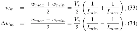
Parameterswmand∆wm: The ellipseW0defines the max-imum and minmax-imum value ofwwhich arewmax=wm+∆wm and wmin = wm − ∆wm, respectively. Parameter wmin is chosen from (24) for a given maximum value Imax of the current. In the same framework, wmax corresponds to a minimum input current value Imin from the expression
wmax≈
Vs
Imin
(31)
since the RMS value ofv is approximately equal to the RMS value of the grid voltage Vs, due to the negligible voltage drop on the inductor. For a given constant load RL, there exists a minimum current Imin since the rectifier represents a boost power electronic device withV¯dc≥√2Vs(for sinusoidal PWM). Therefore, Imin can be calculated as
Imin = 2Vs
RL
. (32)
However, (32) depends on the loadRLand if the load changes, the current might reach lower values. In practice, the controller should be able to operate for any load and even in the case of no load connected to the output. Since in the case of no load, a small current of mA or µA still flows through the converter due to the parasitic elements of the system, i.e. the inductor, the capacitor and the switches, Imin can be chosen relatively small to cover all load cases. It should be noted that in a common control operation of a rectifier, when the current drops to very small values, the PWM is turned OFF and the converter operates as a diode rectifier since there is practically no current measured to define the power factor. Therefore, parameterwmaxis calculated from (31) for a relatively small current Imin.
Now, taking into account (24) and (31), the controller parametersw and∆wmare obtained as
wm =
wmax+wmin
2 =
Vs 2
1
Imin
+ 1
Imax
,(33)
∆wm =
wmax−wmin
2 =
Vs 2
1
Imin − 1
Imax
.(34)
Parameter c: To define a framework for choosing the value of c, a worst case scenario is considered where w starts from wmax and reaches the minimum value wmin at the steady state, by operating on the upper semi-ellipse of W0. In this case, the system starts from a minimum output voltage
Vinitial
dc and reaches a maximum voltage V¯ e dc=
√
VsImaxRL (depending on Imax), i.e. there is a maximum difference
∆Vmax dc =
Vinitial
dc −V¯ e dc
. If one assumes that ts is the settling time needed for w andwq to travel the whole upper semi-ellipse ofW0, which corresponds to an arc with central angle ofπrad, with an angular velocity θ˙, then in the worst case the angular velocity will be π
tsrad/sec (if assumed constant and equal to its maximum value). On this trajectory, the second controller state wq is always less or equal to 1. Then, one can define the maximum angular velocity θ˙max (where wq = 1 and
V¯dc−V
ref dc
= ∆V
max
dc ) to be equal to π
tsrad/secas
˙
θmax=
c∆Vmax dc ∆wm
= π
ts
. (35)
Then parameterc is obtained as
c= π∆wm
ts∆Vdcmax
(36)
for a maximum difference∆Vmax
dc required and a given set-tling timets. In practice, since the angular velocity decreases as soon as V¯dc approaches Vref
dc and also wq ≤ 1, then parameter c can take larger values, or in other words the settling timetscan be chosen much smaller than the original value. Expression (36) just provides a starting value ofcfor a smooth response. Thenccan be increased until a satisfactory response is achieved.
[image:6.595.65.301.658.711.2]After selecting the controller parameters, the proposed current-limiting controller can be implemented as shown in Fig. 3, where it is clear that no PLL or instantaneous mea-surement of the grid voltage is required for the implementation of the controller, opposed to the traditional techniques. This significantly simplifies the implementation of the proposed controller and increases the reliability of the system. It should be noted that a low-pass filter is added at the measurement of the output voltageVdc to remove the second-order harmonics and a phase-lead low-pass filter is added at the measurement of the currentito remove the switching ripples and also apply a small phase-shifting (if needed) in order to obtain unity power factor at the whole system instead of the input of the rectifier, i.e., to cancel the small phase shifting caused by the inductor
L[1].
D. Controller performance under grid voltage variations
Although it is proven that the proposed controller can limit the current when unrealistic values of Vdcref are applied, one of the most challenging tasks is to limit the current under variations of the grid voltage and especially under voltage dips. According to the ISS analysis, it is proven that I < Imax when wmin is selected according to (24). In this case, the grid voltage is considered stiff and Vs = Vn, where Vn is the rated RMS voltage. If it is assumed that the grid voltage introduces variations, i.e. Vs ∈[0, Vmax], where Vmax is the maximum value of the RMS grid voltage, then following the same ISS analysis and taking into account (22)-(23), it yields that
I≤r+Vmaxw
min
L
i +
-u
u u
u +
-vs
r L
i
v C Vdc RL
PWM generator
1 s
- ref dc V c
×
w×
v/
uequation (5) wq phase-lead
low-pass filter low-pass
filter
[image:7.595.330.546.131.204.2]dc V
Figure 3. Implementation of the proposed current-limiting controller
as long as initially the RMS value of the current satisfies the above inequality. Hence, by selecting
wmin=
Vmax
Imax
(38)
then I(t) < Imax,∀t ≥ 0, which guarantees the current-limiting property even when the grid voltage varies. This includes the case where a voltage dip occurs. In order to cal-culate the maximum current during a voltage dip, consider the case where wmin is selected according to (38) and suddenly ap×100%percentage drop occurs at the grid voltage, where 0 ≤ p ≤ 1, i.e. the RMS grid voltage becomes (1−p)Vs, where Vswas the original value of the grid voltage before the fault. Then according to (23) there is
I≤(1−p)Vs r+Vmax
Imax
<(1−p) Vs
Vmax
Imax<(1−p)Imax. (39)
Inequality (39) implies that the current will be limited below a lower value depending on the percentage of the voltage dip. This is due to the fact that the measurement of the grid voltage is not used for the controller design, which significantly simplifies its implementation. Nevertheless, in any case, the input current will be lower than Imax as required to protect the rectifier. Note that the same controller can be extended to applications with an LCL filter instead of an L filter, where the capacitor voltage remains in the range[0, Vmax], depending on the grid voltage and the filter parameters.
IV. EXPERIMENTAL VALIDATION
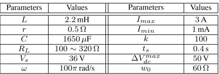
In order to verify the efficiency of the proposed controller, a single-phase full-bridge rectifier with a load resistor RL operating under the proposed current-limiting controller de-scribed in Fig. 3 was experimentally investigated. A switch-ing frequency of 19kHz was used for the PWM opera-tion and the proposed controller was implemented using the TMS320F28335 DSP with a sampling frequency of 16kHz. The system and the controller parameters are given in Table I. Because of the limitations of the input voltage level for
Table I
SYSTEM AND CONTROLLER PARAMETERS
Parameters Values Parameters Values
L 2.2mH Imax 3A
r 0.5 Ω Imin 1mA
C 1650µF k 100
RL 100∼320 Ω ts 0.4s
Vs 36V ∆Vdcmax 50V
ω 100πrad/s w0 60 Ω
the experimental setup, a 36V RMS input voltage was used due to the popularity of 110V/36V transformers. For the controller implementation, the low-pass filter 1
0.01s+1 was used at the measurement of the dc output voltage to reject the second-order harmonics and the phase-lead low-pass filter
31(0.06s+1)
(0.003s+1)(s+270)was used at the measurement of the inductor current to remove the switching ripples and apply a small phase shifting to cancel the effect of the filter inductor. This is commonly used in power converter control applications when a feed-forward term is introduced at the control signal [1]. Note that different types of filters can be used for both measurements (e.g. hold filter for the dc output voltage) but the above filters were considered for simplicity.
A. Operation with normal grid
Initially, the system operates as a diode rectifier with
Vs= 36V and RL = 320 Ω, and the controller is not active. Fig. 4(b) shows the transient response when the controller is enabled with Vdcref = 110V, which corresponds to a typical voltage level in ac or dc power applications. The dc output voltage increases and smoothly converges to the reference value after a short transient, while the unity power factor is maintained during the whole operation. Note that the transient response can be faster if the capacitanceCis reduced, but this will increase the second-order ripples of the output voltage. The smooth transient is due to the proposed controller which applies a varying resistance starting from w0 = 60 Ω and reduces while moving on the desired ellipse W0, as shown in Fig. 4(c) and 4(d). The initial condition ofwq was defined aswq0=
q
1−(w0−wm)2 ∆w2
Vdc: [45 V/div]
Time: [10 ms/div]
vs: [45 V/div]
i: [3.75 A/div]
110 V
0 V,A
(a)
Vdc: [45 V/div]
Time: [100 ms/div]
vs: [45 V/div]
i: [3.75 A/div]
0 V,A 110 V
(b)
Time: [100ms/div]
w: [12Ω/div]
wq: [0.05/div]
(c)
0 20 40 60 80
−0.1 −0.05 0 0.05 0.1
wq
w/Ω
W
0
(d)
Figure 4. Experimental results of the proposed current-limiting controller under normal operation when the controller is enabled withVdcref = 110V
andRL= 320 Ω: (a) steady-state response of the system states, (b) transient
response of the system states, (c) transient response of the controller states, (d)w−wqplane.
accuracy of the measurement and has an impact on the power quality. Note that different current measurement units, filter
Vdc: [45 V/div]
Time: [10 ms/div]
vs: [45 V/div]
i: [3.75 A/div]
110 V
0 V,A
(a)
Vdc: [45 V/div]
Time: [100 ms/div]
vs: [45 V/div]
i: [3.75 A/div]
0 V,A 110 V
(b)
Time: [100ms/div]
w: [12Ω/div]
wq: [0.05/div]
(c)
0 20 40 60 80
−0.1 −0.05 0 0.05 0.1
wq
w/Ω
W
0
(d)
Figure 5. Experimental results of the proposed current-limiting controller under normal operation when the load changes from320 Ωto 220 Ωwith
Vdcref = 110V: (a) steady-state response of the system states, (b) transient response of the system states, (c) transient response of the controller states, (d)w−wq plane.
[image:8.595.74.282.94.699.2] [image:8.595.337.542.99.697.2]controller [47], [48], [49], and are currently investigated. In order to verify the current-limiting property of the controller, the reference output voltage changes from110V to 140V, when the load resistor is220 Ω. However, as it becomes clear from Fig. 6(a), the output voltage is regulated at around 120V because the current tries to violate the maximum limit. Although the limit of the current was set to Imax = 3A, the RMS value of the steady-state current was measured at 2.2A which is slightly less than Imax, since as mentioned in Subsection III-B wmin is calculated from (24) where the parasitic resistance rof the inductorLwas neglected and the power factor is slightly less than 1. However, this still results in
I < Imax which is desired. In practice,Imax can be chosen slightly higher for the selection of wmin to cope with this issue. According to the transient response of the controller states (Fig. 6(c)), w→wmin andwq →0as expected at the limit of the current. This is also shown from the controller state trajectory on the ellipseW0on thew−wq plane, in Fig. 6(d), verifying the theory developed in the paper.
To further validate the current limitation, while the reference dc output voltage is kept constant at Vdcref = 110V, the load changes from 320 Ωto 100 Ω, which is a larger change than the one described in Fig. 5. This causes the input current to increase and be limited again at 2.2A. This leads to a drop of the output voltage from 110V to82V, as shown from the transient and the steady-state responses of the system states in Fig. 7(b) and Fig. 7(a), respectively. Hence, the proposed controller automatically reduces the output voltage to protect the rectifier from large currents. The controller stateswandwq tend towmin and 0, respectively, while operating exclusively on W0, as shown in Fig. 7(c) and Fig. 7(d).
B. Operation under grid voltage dips
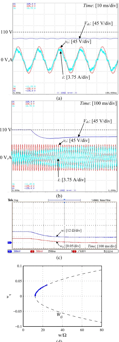
In order to further test the current-limiting capability of the proposed controller, two scenarios of voltage dips at the grid voltage are investigated. The desired output voltage is again set at 110V and the load resistance is RL = 220 Ω for the whole operation. Initially, the RMS grid voltage drops from 36V to 30V, which corresponds to a 17% voltage drop, i.e.
p= 0.17. According to the analysis of Subsection III-D, the current will be limited to a lower value corresponding to83% of the maximum current. As shown in Fig. 8(b), the current increases as the voltage drops and its RMS value is limited at 1.82A, as verified from the steady state response of Fig. 8(a). Since the experimental results of Fig. 6 have indicated that the given controller limits the current at a maximum value of 2.2A, then the analysis of Subsection III-D proves that the current should be limited below 0.83×2.2A = 1.83A, which is the case. The output voltage drops to a lower value to maintain the power equivalence. The controller states w
and wq are regulated at their minimum values wmin and 0, respectively, as shown in Fig. 8(c), and their trajectory stays on W0, as shown in Fig. 8(d).
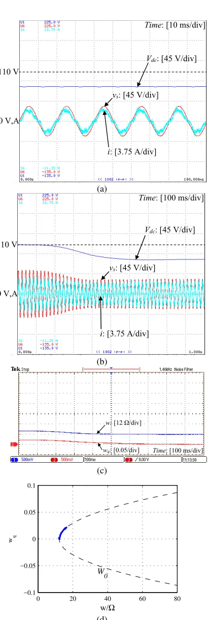
Finally, the RMS of the grid voltage suddenly drops from 36V to23V (36%voltage drop) and the results are shown in Fig. 9. The transient response is illustrated in Fig. 9(b) where the output voltage drops and is regulated to a value lower than
Vdc: [45 V/div]
Time: [10 ms/div]
vs: [45 V/div]
i: [3.75 A/div]
140 V
0 V,A
(a)
Vdc: [45 V/div]
Time: [100 ms/div]
vs: [45 V/div]
i: [3.75 A/div]
0 V,A 140 V
(b)
Time: [100ms/div]
w: [12Ω/div]
wq: [0.05/div]
(c)
0 20 40 60 80
−0.1 −0.05 0 0.05 0.1
wq
w/Ω
W0
[image:9.595.333.542.101.687.2](d)
Figure 6. Experimental results of the proposed controller reaching the current limit when theVdcrefchanges from110V to140V (current limiting activated
with V¯
dc → 120V): (a) steady-state response of the system states, (b) transient response of the system states, (c) transient response of the controller states, (d)w−wqplane.
Vdc: [45 V/div]
Time: [10 ms/div]
vs: [45 V/div]
i: [3.75 A/div]
110 V
0 V,A
(a)
Vdc: [45 V/div]
Time: [100 ms/div]
vs: [45 V/div]
i: [3.75 A/div]
0 V,A 110 V
(b)
Time: [100ms/div]
w: [12Ω/div]
wq: [0.05/div]
(c)
0 20 40 60 80
−0.1 −0.05 0 0.05 0.1
wq
w/Ω
W
0
[image:10.595.71.279.101.697.2](d)
Figure 7. Experimental results of the proposed controller reaching the current limit when the load changes from 320 Ω to 100 Ω with Vdcref = 110V
(current limiting activated with V¯
dc → 82V): (a) steady-state response of the system states, (b) transient response of the system states, (c) transient response of the controller states, (d)w−wqplane.
This is clearly shown from the steady-state response of Fig. 9(a). As in the previous case, the controller states w and
wq converge to wmin and 0, respectively, while moving on the desired ellipse (Fig. 9(c) and Fig. 9(d)). As a result, it is verified that even when voltage dips occur at the grid, the proposed controller maintains the input current below a maximum value without requiring the measurement of the grid voltage, sag detection mechanisms or additional protection devices.
V. CONCLUSIONS
In this paper, a nonlinear controller with an inherent current-limiting capability was proposed for single-phase rectifiers. The developed strategy guarantees nonlinear asymptotic sta-bility and convergence to a unique solution at all times, while achieving the main tasks of the rectifier operation, i.e., accurate output voltage regulation and unity power factor operation. An analytic description of the controller parameters selection was provided to guarantee that the input current will be limited below a given value during transients even if the grid voltage varies. Opposed to the existing control techniques, the proposed current-limiting controller is fully independent from the system parameters and does not require a PLL or the instantaneous measurement of the grid voltage, leading to a simplified implementation. Extensive experimental results were provided to support the theoretical background of the proposed approach and verify its effective operation.
It is worth noting that the use of a positive dynamic virtual resistance in the proposed controller structure can guarantee the required stability but restricts the proposed controller application only to rectifiers and not to inverters. Hence, this represents a simplified control approach for rectifier-fed passive loads. Further investigation is required to obtain a generic structure that can be applied to both types of ac/dc converters with different operating conditions (e.g. constant power, constant current loads) and satisfy some additional practical limitations (e.g. saturation of the control input) with an improvement of the power quality. These issues represent interesting topics for future research.
REFERENCES
[1] Q.-C. Zhong and T. Hornik,Control of Power Inverters in Renewable Energy and Smart Grid Integration. Wiley-IEEE Press, 2013. [2] C. Meza, D. Biel, D. Jeltsema, and J. M. A. Scherpen, “Lyapunov-Based
Control Scheme for Single-Phase Grid-Connected PV Central Inverters,”
IEEE Trans. Control Syst. Technol., vol. 20, no. 2, pp. 520–529, 2012. [3] G. C. Konstantopoulos and Q.-C. Zhong, “Current-limiting non-linear controller for single-phase AC/DC PWM power converters,” in 2015 American Control Conference (ACC), Chicago, IL, July 1-3 2015, pp. 1029–1034.
[4] J. G. Hwang, P. W. Lehn, and M. Winkelnkemper, “A generalized class of stationary frame-current controllers for grid-connected AC-DC converters,”IEEE Trans. Power Del., vol. 25, no. 4, pp. 2742–2751, Oct 2010.
[5] O. Stihi and B.-T. Ooi, “A single-phase controlled-current PWM recti-fier,”IEEE Trans. Power Electron., vol. 3, no. 4, pp. 453–459, 1988. [6] O. Kükrer and H. Kömürcügil, “Control strategy for single-phase PWM
rectifiers,”Electronics Letters, vol. 33, no. 21, pp. 1745–1746, 1997. [7] D. Karagiannis, E. Mendes, A. Astolfi, and R. Ortega, “An experimental
comparison of several PWM controllers for a single-phase AC-DC converter,”IEEE Trans. Control Syst. Technol., vol. 11, no. 6, pp. 940– 947, 2003.
Vdc: [45 V/div]
Time: [10 ms/div]
vs: [45 V/div]
i: [3.75 A/div]
110 V
0 V,A
(a)
Vdc: [45 V/div]
Time: [100 ms/div]
vs: [45 V/div]
i: [3.75 A/div]
0 V,A 110 V
(b)
Time: [100ms/div]
w: [12Ω/div]
wq: [0.05/div]
(c)
0 20 40 60 80
−0.1 −0.05 0 0.05 0.1
wq
w/Ω
W0
(d)
Figure 8. Experimental results of the proposed current-limiting controller when the RMS input voltage changes from 36V to30V (current limiting activated withV¯
dc→100V): (a) steady-state response of the system states, (b) transient response of the system states, (c) transient response of the controller states, (d)w−wqplane.
[9] T.-S. Lee, “Lagrangian modeling and passivity-based control of three-phase AC/DC voltage-source converters,”IEEE Transactions on Indus-trial Electronics, vol. 51, no. 4, pp. 892–902, 2004.
Vdc: [45 V/div]
Time: [10 ms/div]
vs: [45 V/div]
i: [3.75 A/div]
110 V
0 V,A
(a)
Vdc: [45 V/div]
Time: [100 ms/div]
vs: [45 V/div]
i: [3.75 A/div]
0 V,A 110 V
(b)
Time: [100ms/div]
w: [12Ω/div]
wq: [0.05/div]
(c)
0 20 40 60 80
−0.1 −0.05 0 0.05 0.1
wq
w/Ω
W
0
(d)
Figure 9. Experimental results of the proposed current-limiting controller when the RMS input voltage changes from 36V to 23V (current limiting activated withV¯
dc→77V): (a) steady-state response of the system states, (b) transient response of the system states, (c) transient response of the controller states, (d)w−wqplane.
[image:11.595.74.280.84.694.2] [image:11.595.337.542.86.697.2]Technol., vol. 18, no. 2, pp. 323–335, 2010.
[11] T. Jin, L. Li, and K. M. Smedley, “A universal vector controller for four-quadrant three-phase power converters,”IEEE Trans. Circuits Syst. I: Reg. Papers, vol. 54, no. 2, pp. 377–390, 2007.
[12] D. del Puerto-Flores, J. M. A. Scherpen, M. Liserre, M. M. J. de Vries, M. J. Kransse, and V. Giuseppe Monopoli, “Passivity-based control by series/parallel damping of single-phase PWM voltage source converter,”
IEEE Trans. Control Syst. Technol., vol. 22, no. 4, pp. 1310–1322, 2014. [13] T.-S. Lee, “Input-output linearization and zero-dynamics control of three-phase AC/DC voltage-source converters,” IEEE Trans. Power Electron., vol. 18, no. 1, pp. 11–22, 2003.
[14] H. Kömürcügil and O. Kükrer, “Lyapunov-based control for three-phase PWM AC/DC voltage-source converters,”IEEE Trans. Power Electron., vol. 13, no. 5, pp. 801–813, 1998.
[15] A. Gensior, H. Sira-Ramà rez, J. Rudolph, and H. GÃijldner, “On some nonlinear current controllers for three-phase boost rectifiers,”IEEE Trans. Industrial Electron., vol. 56, no. 2, pp. 360–370, 2009. [16] Y. Zhang, Y. Peng, and H. Yang, “Performance improvement of
two-vectors-based model predictive control of PWM rectifier,”IEEE Trans. Power Electron., vol. 31, no. 8, pp. 6016 – 6030, 2016.
[17] O. Kukrer, H. Komurcugil, and A. Doganalp, “A three-level hysteresis function approach to the sliding-mode control of single-phase UPS inverters,”IEEE Trans. Ind. Electron., vol. 56, no. 9, pp. 3477–3486, 2009.
[18] A. Dell’ Aquila, M. Liserre, V. Giuseppe Monopoli, and P. Rotondo, “Overview of PI-based solutions for the control of DC buses of a single-phase H-bridge multilevel active rectifier,”IEEE Trans. Ind. Appl., vol. 44, no. 3, pp. 857–866, 2008.
[19] R. Teodorescu, F. Blaabjerg, M. Liserre, and P. C. Loh, “Proportional-resonant controllers and filters for grid-connected voltage-source con-verters,”IEE Proc.-Electric Power Applications, vol. 153, no. 5, pp. 750–762, 2006.
[20] C. Cecati, A. Dell’Aquila, M. Liserre, and A. Ometto, “A fuzzy-logic-based controller for active rectifier,”IEEE Trans. Ind. Appl., vol. 39, no. 1, pp. 105–112, Jan 2003.
[21] R. Ghosh and G. Narayanan, “A single-phase boost rectifier system for wide range of load variations,”IEEE Trans. Power Electron., vol. 22, no. 2, pp. 470–479, 2007.
[22] R. Martinez and P. N. Enjeti, “A high-performance single-phase rectifier with input power factor correction,” IEEE Trans. Power Electron., vol. 11, no. 2, pp. 311–317, 1996.
[23] R. Ortega, A. Loria, P. J. Nicklasson, and H. Sira-Ramirez, Passivity-based Control of Euler-Lagrange Systems, Mechanical, Electrical and Electromechanical Applications. Springer-Verlag. Great Britain, 1998. [24] H. Komurcugil, N. Altin, S. Ozdemir, and I. Sefa, “An extended Lyapunov-function-based control strategy for single-phase UPS invert-ers,”IEEE Trans. on Power Electron., vol. 30, no. 7, pp. 3976–3983, 2015.
[25] M. Hernandez-Gomez, R. Ortega, F. Lamnabhi-Lagarrigue, and G. Es-cobar, “Adaptive PI stabilization of switched power converters,”IEEE Trans. Control Syst. Technol., vol. 18, no. 3, pp. 688–698, 2010. [26] G. Escobar, D. Chevreau, R. Ortega, and E. Mendes, “An adaptive
passivity-based controller for a unity power factor rectifier,”IEEE Trans. Control Syst. Technol., vol. 9, no. 4, pp. 637–644, 2001.
[27] G. F. Montgomery, “Current-limited rectifiers,”Proceedings of the IRE, vol. 50, no. 2, pp. 190–193, Feb 1962.
[28] C. C. Herskind and H. L. Kellogg, “Rectifier fault currents,”Electrical Engineering, vol. 64, no. 3, pp. 145–150, March 1945.
[29] J. Lira, N. Visairo, C. Nunez, A. Ramirez, and H. Sira-Ramirez, “A robust nonlinear control scheme for a sag compensator active multilevel rectifier without sag detection algorithm,”IEEE Trans. Power Electron., vol. 27, no. 8, pp. 3576–3583, 2012.
[30] N. Visairo, C. Nunez, J. Lira, and I. Lazaro, “Avoiding a voltage sag detection stage for a single-phase multilevel rectifier by using control theory considering physical limitations of the system,” IEEE Trans. Power Electron., vol. 28, no. 11, pp. 5244–5251, 2013.
[31] P. Rioual, H. Pouliquen, and J. P. Louis, “Regulation of a PWM rectifier in the unbalanced network state using a generalized model,”IEEE Trans. Power Electron., vol. 11, no. 3, pp. 495–502, May 1996.
[32] A. D. Paquette and D. M. Divan, “Virtual impedance current limiting for inverters in microgrids with synchronous generators,”IEEE Trans. Ind. Appl., vol. 51, no. 2, pp. 1630–1638, 2015.
[33] M. Huang, S.-C. Wong, C. K. Tse, and X. Ruan, “Catastrophic bifur-cation in three-phase voltage-source converters,”IEEE Trans. Circuits Syst. I: Reg. Papers, vol. 60, no. 4, pp. 1062–1071, 2013.
[34] H. J. Laaksonen, “Protection principles for future microgrids,” IEEE Trans. Power Electron., vol. 25, no. 12, pp. 2910–2918, 2010.
[35] Y. Yang, F. Blaabjerg, and H. Wang, “Low-voltage ride-through of single-phase transformerless photovoltaic inverters,” IEEE Trans. Ind. Appl., vol. 50, no. 3, pp. 1942–1952, 2014.
[36] M. S. El Moursi, W. Xiao, and J. L. Kirtley, “Fault ride through capa-bility for grid interfacing large scale PV power plants,”IET Generation, Transmission & Distribution, vol. 7, no. 9, pp. 1027–1036, 2013. [37] A. B. Youssef, S. K. E. Khil, and I. Slama-Belkhodja, “State
observer-based sensor fault detection and isolation, and fault tolerant control of a single-phase PWM rectifier for electric railway traction,”IEEE Trans. Power Electron., vol. 28, no. 12, pp. 5842–5853, 2013.
[38] N. Bottrell and T. C. Green, “Comparison of current-limiting strategies during fault ride-through of inverters to prevent latch-up and wind-up,”
IEEE Trans. Power Electron., vol. 29, no. 7, pp. 3786–3797, 2014. [39] J. Rohten, J. Espinoza, J. Munoz, M. Perez, P. Melin, J. Silva, E.
Es-pinosa, and M. Rivera, “Model predictive control for power converters in a distorted three-phase power supply,”IEEE Trans. Ind. Electron., to appear.
[40] L. Zaccarian and A. R. Teel, “Nonlinear scheduled anti-windup design for linear systems,”IEEE Trans. Autom. Control, vol. 49, no. 11, pp. 2055–2061, 2004.
[41] S. Galeani, S. Onori, and L. Zaccarian, “Nonlinear scheduled control for linear systems subject to saturation with application to anti-windup control,” in46th IEEE Conference on Decision and Control, 2007, pp. 1168–1173.
[42] S. Tarbouriech and M. Turner, “Anti-windup design: an overview of some recent advances and open problems,” IET Control Theory & Applications, vol. 3, no. 1, pp. 1–19, 2009.
[43] H. K. Khalil,Nonlinear Systems. Prentice Hall, 2001.
[44] R. Sira-Ramirez, H.and Silva-Ortigoza,Control Design Techniques in Power Electronics Devices. Springer, London, 2006.
[45] S. Wang, X. Ruan, K. Yao, S.-C. Tan, Y. Yang, and Z. Ye, “A flicker-free electrolytic capacitor-less AC–DC LED driver,”IEEE Trans. Power Electron., vol. 27, no. 11, pp. 4540–4548, 2012.
[46] S. Wiggins,Introduction to Applied Nonlinear Dynamical Systems and Chaos, 2nd ed., N. Y. Springer, Ed., 2003.
[47] A. Kwasinski, P. T. Krein, and P. L. Chapman, “Time domain com-parison of pulse-width modulation schemes,”IEEE Power Electronics Letters, vol. 1, no. 3, pp. 64–68, 2003.
[48] S. R. Bowes and S. Grewal, “Modulation strategy for single phase pwm inverters,”Electronics Letters, vol. 34, no. 5, pp. 420–422, 1998. [49] M. Meco-Gutierrez, J. R. Heredia-Larrubia, F. Perez-Hidalgo, A.
Ruiz-Gonzalez, and F. Vargas-Merino, “Pulse width modulation technique parameter selection with harmonic injection and frequencymodulated triangular carrier,”IET Power Electronics, vol. 6, no. 5, pp. 954–962, 2013.
George C. Konstantopoulos(S’07-M’13) received
his Diploma and Ph.D. degrees in electrical and computer engineering from the Department of Elec-trical and Computer Engineering, University of Pa-tras, Rion, Greece, in 2008 and 2012, respectively.
Qing-Chang Zhong (M’03-SM’04) received the
Ph.D. degree in control and power engineering (awarded the Best Doctoral Thesis Prize) from Impe-rial College London, London, U.K., in 2004 and the Ph.D. degree in control theory and engineering from Shanghai Jiao Tong University, Shanghai, China, in 2000.
He holds the Max McGraw Endowed Chair Pro-fessor in Energy and Power Engineering at the Dept. of Electrical and Computer Engineering, Illinois Institute of Technology, Chicago, USA, and the Re-search Professor in Control of Power Systems at the Department of Automatic Control and Systems Engineering, The University of Sheffield, UK. He is a Distinguished Lecturer of both the IEEE Power Electronics Society and the IEEE Control Systems Society. He (co-)authored three research monographs: Control of Power Inverters in Renewable Energy and Smart Grid Integration (Wiley-IEEE Press, 2013), Robust Control of Time-Delay Systems (Springer-Verlag, 2006), Control of Integral Processes with Dead Time (Springer-(Springer-Verlag, 2010), and a fourth, Power Electronics-enabled Autonomous Power Systems: Next Generation Smart Grids, is scheduled for publication by Wiley-IEEE Press. He proposed the architecture for the next-generation smart grids, which adopts the synchronization mechanism of synchronous machines to unify the interface and interaction of power system players with the grid and achieve autonomous operation of power systems. His research focuses on power electronics, advanced control theory and the integration of both, together with applications in renewable energy, smart grid integration, electric drives and electric vehicles, aircraft power systems, high-speed trains etc.