Theses
Thesis/Dissertation Collections
5-2005
Vision application of human robot interaction:
Development of a ping pong playing robotic arm
Kalpesh Prakash Modi
Follow this and additional works at:
http://scholarworks.rit.edu/theses
This Thesis is brought to you for free and open access by the Thesis/Dissertation Collections at RIT Scholar Works. It has been accepted for inclusion
in Theses by an authorized administrator of RIT Scholar Works. For more information, please contact
Recommended Citation
DEVELOPMENT OF A PING PONG PLAYING ROBOTIC ARM
By
KALPESH PRAKASH MODI
Thesis submitted in partial fulfillment
of
the requirements for the degree of
Thesis Advisor
Thesis Committee
Thesis Committee
Department Head
MASTER OF SCIENCE
IN
ELECTRICAL ENGINEERING
Approved
by
Dr. Ferat Sahin
Dr. Eli Saber
Dr. Wayne Walter
Dr. Robert Bowman
Ferat Sahin
Eli Saber
Wayne Walter
Robert Bowman
DEPARTMENT OF ELECTRICAL ENGINEERING
,
KATE GLEASON COLLEGE OF ENGINEERING
ROCHESTER INSTITUTE OF TECHNOLOGY
ROCHESTER, NEW YORK
Thesis Release Permission Form
Rochester Institute of Technology
Kate Gleason College of Engineering
VISION APPLICATION OF HUMAN ROBOT INTERACTION:
DEVELOPMENT OF A PING PONG PLAYING ROBOTIC ARM
I, Kalpesh Prakash Modi hereby grant the permission to the Wallace Library of the
Rochester Institute of Technology to reproduce my thesis in whole or in part. Any
reproduction will not be for commercial use or profit.
Author
:
Kalpesh Modi
Dedicated
to
My
parents,
Mr. Prakash
andMrs. Meena
Modi,
whohave
alwaysblessed
me withtheir
inspirational
supportfor
demonstrating
persistentand sincere effortsthroughout
and
My
loving
sisterBosky,
whohas
always cheered andbolstered
methrough
her
optimismin my
approaches.Acknowledgments
I
take this
opportunity
to
expressmy
utmost respectfor Dr. Ferat
Sahin,
whohas
advised,
guided and steered meenroute, through
my Master's degree
withimmense
care.Under his
supervision,
I
was ableto
develop
the
habit
to
prepare myselffor
a problemand
then
solveit thoroughly,
by
almostnullifying
the
pressurefactor. I
thank
him
earnestly for his faith in
me ashis
graduate student and whilstincluding
me as a memberof
his Robotics Lab.
I convey my
sincere gratitudeto
Dr. Eli Saber
for his keen counseling
and salutehis proficiency in Image
andVideo Processing. It
wasin his mentoring
only,
that
I
soughtmotivation
to
workhard independently. I
thank
him
andDr. Wayne Walter for assessing
the
workin
this thesis.
A
special vote of respectful appreciationto the
Head,
Dr. Robert Bowman for
providing
me with anopportunity
to
pursuemy degree in Electrical Engineering.
Many
thanks to
Mr. Kenneth Snyder
andMr. James Stefano for availing
me withthe
privilegesand
technical
assistanceto
operatethe
lab
and system utilities.I
am alsothankful to
Ms.
Patty
Vicari,
Ms. Florence Layton
andMs. Jill Lewis
for
assisting
meto
keep
track
ofmy
academic and registration status
throughout
my degree.
I
amhighly
gratefulto
Mr. Mark
Chast,
Sr.
Systems
Administrator in
the
College
ofEngineering,
for acquainting
me aboutkey
issues pertaining
to
Linux
andprogramming
andproviding
aboost for applying
them
in
this
thesis.
I
amextremely
thankful to
Dr.
Josef
Torok,
for
bestowing
uponme,
a chanceto
servethe
Dean's
officeinterface
ofthe
ping pong
paddle.As
aninternational
student,
I
am obligedto
Ms. Lilli Jensen
atthe
International
Student
Office,
for her
utmost practicalcounseling
towards
my stay
and servicesfor
the
United States. I
am alsoindebted
to
Dr.
Howard Ward
ofHousing
operations,
for
facilitating
meto
utilizethe time
andmonetary benefits
ofliving
oncampus.My
best
regardsto
Mr. Lawrence Brown
andMs. Alfreda Brown for
their
intense
familial
support,
love
and care.I
also expresshigh
esteemtowards
my
family
membersback home for
their
assurance and confidein my
pursuitfor higher
education.VISION APPLICATION OF
HUMAN ROBOT
INTERACTION:
DEVELOPMENT OF
A PING PONG PLAYING ROBOTIC ARM
By
KALPESH
PRAKASH
MODI
Master
ofScience in
Electrical
Engineering
Abstract
Robotics is
a sciencethat
is
implemented
parallelto
human
behavior.
This
workdescribes
andimplements
techniques to
mathematically
modelthe
game ofping pong
played
by
the
humans,
and utilization ofthese
methodsin
the
design
anddevelopment
ofa
ping pong playing
robotic arm as an application of robotic vision.Displaced
frame
difference
(DFD)
is
usedto
segmentthe
ball
motionfrom background
motion andparametric calibration of single
CCD
camerais
utilizedto
track
the
ball
in
three
dimensions. This
visualinformation is
temporally
updated andfurther
appliedto
guide arobot arm
to
hit
the
ball
at a specifiedlocation in
time.
The
resultssignify
the
systemdevelopment based
on single cameratracking
and alsodemonstrate
its working
withself-sufficiency for
the
color ofthe
ball. System
latency
is
measured as afunction
ofthe
camera
interface,
processorarchitecture,
and robot motion.Various
hardware
andsoftware parameters
that
influence
the
realtime
systemperformance are alsodiscussed.
Table
of
Contents
Thesis Release Permission Form
ii
Acknowledgments
iv
Abstract
viTable
ofContents
viiList
ofFigures
xList
ofTables
xiii1.
Introduction
1
1.1
Motivation
1
1.2
Objective
3
1.3
Nomenclature
5
2.
System
Theory
7
2.1
Introduction
7
2.2
Digital Signal
Processing
7
2.3
Computer Vision
9
2.4
Ping
pong
robot system15
2.4.1
Vision
system16
2.4.2
Trajectory
Analysis
23
2.4.3
Expert
controller24
3.
System Configuration
27
3.1
Introduction
27
3.2.1
Workstation
28
3.2.2
Camera
30
3.3
Robot
30
4.
System Implementation
33
4.1
Introduction
33
4.2
System Design
33
4.2.1
Frame
acquisition34
4.2.2
Motion
andBall detection
35
4.2.3
Ball location in
the
image
plane46
4.2.4
Camera
calibration and3-D
Imaging
50
4.2.5
Motion Estimation
59
4.2.6
Target
point computation64
4.2.7
Robot
motion67
5.
Experimental Procedure
andAnalysis
70
5.1
Foreword
70
5.2
System
setup
70
5.2.1
Camera
calibration70
5.2.2
Paddle interface
and robotpositioning
76
5.2.3
Software
control77
5.3
System
performance7g
5.3.1
Frame
capturerate andprocessing
time
78
5.3.3
Motion detection
80
5.3.4
Ball detection
82
5.3.5
Ball location in
the
image
plane83
5.3.6
3-D
Imaging
84
5.3.7
Displacement
89
5.3.8
Trajectory
estimation andtarget
point computation92
6.
Conclusion
94
6.1
Synopsis
94
6.2
Performance
analysis95
6.3
Future
workbased
on currentlimitations
96
References
98
Figure 2-1 Image formation
on camera9
Figure 2-2 Structural flow
ofComputer Vision
10
Figure 2-3. Hardware
and softwarecategorization of computer visionblocks
14
Figure 3-1
Ping-pong
system27
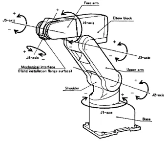
Figure 3-2 Robot
parts and co-ordinates31
Figure 3-3 Major
axes ofthe
robot32
Figure 4-1 System block diagram
33
Figure 4-2 Acquisition data flow
34
Figure 4-3 Video
as a sequence offrames
35
Figure 4-4 DPCM:
Redundancy
reduction37
Figure 4-5 Motion detection
regionin DFD
39
Figure 4-6 Motion sensing
40
Figure 4-7 DFD for
detecting
changesin
scene41
Figure 4-9 Ball
silhouette46
Figure
4-10 Circle-ellipse similarity
47
Figure
4-11 Point
representationon a circle and an ellipse48
Figure 4-12 Tilt in
the
XY
plane48
Figure 4-13 Focal length
of camera51
Figure 4-15 Pixel
to
millimetertransformation
54
Figure 4-16 3-D
Imaging
based
onscene and objecttopology
56
Figure 4-17 Free
body
diagram
of a projectile61
Figure 4-18 Displacement in 3-D
62
Figure 4-19 Coefficient
of restitution65
Figure 4-20 Motion
estimation66
Figure 4-21 Target
point computation67
Figure 4-22 Robot
motion68
Figure 5-1 Experimental
top
view offocal length
computation71
Figure 5-2 Experimental
observationfor
changein ball
size72
Figure
5-3 Ball distance
vs. size73
Figure
5-4 Resolution in
mm74
Figure
5-5 Side
view ofthe
scenetopology
76
Figure
5-6 DFD
identifying
a colorball
79
Figure
5-7 DFD
identifying
a whiteball
80
Figure
5-8
Binarization
for
colorball
81
Figure 5-9
Binarization
for
whiteball
82
Figure 5-10 Ball
segmentation83
Figure
5-1 1 Single
camerabased 3-D
tracking
of colorball
87
Figure 5-12 Single
camerabased 3-D
tracking
of whiteball
88
89
Figure 5-15
Estimated
trajectory
92
List
of
Tables
Table 1-1
Computer
vision applications2
Table 2-1
Classification
of signals8
Table 2-2 Acquisition
componentsfor ping pong
robot system16
Table 2-3 Robot
and controller specifications25
Table 4-1
Trajectory
based
motion estimation63
Table 4-2
Trajectory
matrix64
Table 5-2 Horizontal
resolution84
Table 5-3 Vertical
resolution84
Table 5-4 Focal length
85
1.1
Motivation
Primates
adaptthemselves to their
habitat
by
perceiving
changesthrough their
senses and
responding appropriately
to them.
Vision
is
their
most powerful sense asit
provides a
detailed
three
dimensional
knowledge
ofthe
surrounding
world.This
enablesthem to
noticethe
dynamics in
the
visualized environment andinteract
accordingly.Over
the
last
twenty
years,
science andengineering
have
developed
rapidly
and areconcurrently
appliedto
increase
machine(artificial)
intelligence. For
machinesalso,
vision
is
a potentialinterface
withthe
system asit facilitates sensing
of objects andtracking
changesin
the
scene.Human-computer interaction
is
arelatively
newdiscipline,
which aims atthe
scientific
study
of people's communication with computers and applications of associatedexpertise.
This
sociotechnologicalfield has
advancedenormously
towards
recognizing
and
improving
ourrelationship
with computerbased
technologies.
Human-robot
interaction
is
an applied areathat
intends
to
comprehendthe
behavioral
aspectsbetween
human
and a robot andincludes
study,
design
anddevelopment
ofcomputing
systemsfor
a measure of
their
joint
performance.This
performance canbe
evaluatedthrough
techniques,
which comparehuman
and robotproductivity in
ateam
environment[1].
Computer
visionis
such a scientifictool,
whichis
usedto
measurethe
mutualrange
finding,
segmentation,
stereovision,
shapemodeling,
object recognition andtracking [2, 3, 4, 5,
6,
7, 8,
9]. Applications
that
were considered creativeimaginations
are
successfully
employedin
the
real worldtoday.
Table
1-1
summarizesthe
computervision methods
that
have been
appliedto
solve various real world problems.Table 1-1 Computer
visionapplicationsIndustry
Computer
visiontechniques
Graphics
andmultimedia
3
-D
Pipelining
(transformation, lighting,
setup, rendering),
virtual
reality,
telepresence,
videoindexing,
inter
andintra
frame
coding,
objectlayer based
video coding.Medical
imaging
Image
registration,
image
fusion, X-Ray
based
computedtomography (CT),
magnetic resonanceimaging
(MRI),
opticaldiagnosis.
Sports
3
-D
virtualsimulation,
playertracking,
objecttracking,
sceneanalysis.
Security
andsurveillance
Automatic
target
recognition,
motiondetection
andmonitoring,
aerial
navigation,
number plateidentification,
biometric
measurements.
Power-driven
andInspections,
defect detection
andquality
control,
spray
painting,
data
sets orfrom
real-time sequencesusing sensory devices. Another
application ofcomputer vision
focuses
ondeveloping
guiding
tools
for
persons with visualimpairments,
including
low
vision andblindness.
Currently,
surgical systemslike
the
da
Vinci
use 3-D
imaging
technology
that
allows ahuman
surgeonto
get closerto the
surgical site
than
human
vision andhence
enableshigh
precision endoscopic operations[10].
Thus,
visionis
aninstructive
means offeedback for
survey,
navigation and control.This
research anddevelopment is driven
by
the
desire
to
understand anddesign
avision
based
systemthat
canbe
navigated and controlledfor interaction
withhumans.
1.2
Objective
In
this work,
a robotic vision systembased
onspatio-temporally
sampled visualinformation
is developed. This
time
based
visiondata is
analyzedin
three
dimensions
ofthe
real world and afeedback is
generatedto
communicate withthe
robotin planning its
motion
to
achievethe task
ofhitting
the
ball.
Development
of advancedsensing
systemsis
vitalin
the
continued advancementof robotics
field [11]. Analogous
withthe
human
characteristics,
visualinformation is
highly
significantto
acquireinformation
ofthe
surroundings and navigatethe
robotfor
aspecific
task.
For
extraction of realtime
knowledge
aboutthe
dynamically
changing
environment,
visual sensors areincluded
in
the
feedback
loop
[12].
This
workcomputation of real world
dynamics. These
motiondynamics
arefurther
appliedto the
robot
for
striking
the
ball.
Video
sequences sampledregularly every
15
hertz
are acquiredthrough
aCharged
Couple device
{CCD)
camerainterface
to
obtain sceneinformation.
Motion
is
detected
through the temporal
changein
the
brightness
values(gray levels)
in
the
image
plane
[6,
13]. Motion based image
segmentation and objectdetection
techniques
are usedto
locate
the
ball in
the
image
plane.3-D image
reconstructionis
performedbased
onthe
geometry
ofthe
universal coordinates andframe
transformations
developed for
perspectivecamera vision.
Furthermore,
atrajectory
pathsymbolizing
the velocity
ofball
in
three
dimensions is
extrapolated.This
motiondata
is
updatedevery fifteenth
of asecond and
is
used asfeedback
to
guidethe
robotic armfor
movement,
through
a serialcomputer
interface. Figure 1-1 illustrates
a pictorial representation ofthe
camerabased
robot system
developed.
Motion
data
feed
r
Perspective
frame
capture
A
&
3-D
Ball
tracking
andmotion estimation
feedback
Robot
motion controlto
hit
the
ball
atestimated
target
location
corresponding
movementfor
hitting
the
ball. The
main objective ofthis
workis
to
develop
a single camera visionbased
systemfor surveying
the
scene andtracking
aball
in
three
dimensions.
This dynamic information is further
analyzed and utilized asfeedback
to
navigate a robotto
hit
the
ball
atthe
specifiedtarget.
1.3
Nomenclature
Subsequent
chaptersin
this
documentation describe
Literature
review of computer visiontechnology
andits
application,
particularly
for
the
development
ofthe
ping pong
robot system.Controller
system configuration.Algorithm
for
tracking
the
ball in
a3
-D
space
using
singlecamera.Trajectory
problem andcomputation.System design
and experimentation.Simulation
and performance results ofthe
realizedping-pong
robotsystem.Chapter 2
contains aliterature survey
ofthe
computer visiontechniques
andvarious
ping-pong
robot systemsdeveloped. This
providesthe
background
theory
for
computational aspects of
the
spatio-temporalsensory
information
andthe
robot'sresponse
to the
visualfeedback.
A
conceptualframework
stating
the
processesinvolved
in
the
systemis
explained.The
essential mathematical and geometrical
formulations
usedfor
developing
the
algorithmare alsoexplained.
Information
with respectto the
camerapositioning
andbase mounting
are
discussed in
this
chapter.Chapter
5 lists
the
experimental procedurefor
the
ping pong playing
robotsystem and presents
the
simulation resultsbased
onthis
experimentalframework
described. Performance
resultsvalidating
the
outcome ofthis
research anddevelopment
are also mentioned
in
this
chapter.Chapter 6 discusses
the
conclusionsderived from
this
research anddevelopment.
Various
hardware
and software parametersthat
influence
the
realtime
systemperformanceare also
discussed.
References
list
the
citationsandbooks
studiedfor
this thesis.
Appendix A
consists of aCD-ROM
that
containsthe
source codefor
Simulation
andtesting
ofthe
developed
algorithmusing Matlab
Source
codefor
realtime
systemimplementation in C
2.1
Introduction
This
chapter presents aliterature
review on signalprocessing
andthe
computervision
technology,
particularly
as an applicationfor
the
ping pong
systemdesign.
Further,
theoretical
knowledge
for
the
development
ofthis
systemis
reviewed.An
evaluationbased
on a comparison of variousping pong
systems withthe
systemdeveloped in
this
thesis
is
summarizedatthe
end ofthis
chapter.2.2
Digital Signal
Processing
Digital Signal
Processing
is
an area of science andengineering
that
has developed
rapidly
overthe
pastthirty
years as a result ofthe
significant advancesin digital
computer
technology.
A
signalis defined
asany
physicalquantity
that
varies withtime,
space or
any
otherindependent
variable or variables.Mathematically,
a signalis
afunction
of one or moreindependent
variables,
e.g.speech,
music, picture,
video.Various
types
of signals aredefined
depending
onthe
nature ofthe
independent
variables andthe
value of
the
function
defining
the
signal.For
instance,
a 1-D
signalis
afunction
of oneindependent
variable;
2
-D
signalis
afunction
oftwo
independent
variables and so on.Thus,
a signal carriesinformation
andthe
goal of signalprocessing
is
to
extract usefulinformation
carriedby
the
signal[14].
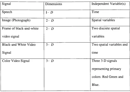
Table 2-1
classifiesdifferent
types
of signals.An image
canbe defined
as atwo-dimensional
function, f{x,y)
where x andcorresponding
to
row x and columny
.The
amplitudeTable 2-1 Classification
of signalsSignal
Dimensions
Independent
Variable(s)
Speech
1-D
Time
Image
(Photograph)
2-D
Spatial
variablesFrame
ofblack-and-white
video signal
2-
D
Two discrete
spatialvariables
Black-and White Video
Signal
3-
D
Two
spatial variables and
time
Color Video Signal
3-D
Three 3-D
signalsrepresenting primary
colors:
Red Green
andBlue.
In biological
vision, the
eyeis
a simple opticalinstrument
as comparedto the
process of recognition.
With internal images
projectedfrom
the
objectsin
the
outsideworld,
it is Plato's
cave with alens [16]. The
visualability
ofhumans
and other animalsis
the
interaction
oflight,
eyes andthe
brain. Visual
perceptiontakes
placeby
the
relativeexcitation of
light
receptors,
whichtransform
radiantenergy into
electricalimpulses
that
are
ultimately decoded
by
the
brain [15]. The
role of camerain
computer visionis in
parity
withthat
of an eyein biological
vision.The
optical componentofthe
camerais
the
sensor of a camerawhere electromagnetic
energy is
transformed
into
electrical signalsto
form
animage,
asillustrated
by
Figure 2-1.
Image
formation
on sensor
Figure 2-1 Image formation
on cameraThus,
animage is
a spatial representation of anobject,
atwo-dimensional
orthree-dimensional scene,
or anotherimage. It
canbe
realorvirtual,
asin
optics[17].
2.3
Computer Vision
In
orderto
interact
withthe surrounding,
it is necessary
to
gainknowledge
aboutthe
data in
the
surrounding.Vision
is
an efficient source ofdata
acquisition andis
usedto
regulate
behavior
withthe
environmentin
adesired
way.Computer
visionis
an appliedscience
that
develops
the theoretical
and algorithmicbasis
by
which usefulinformation
about
the
world canbe
automatically
extracted and analyzedfrom
an observedimage,
image
set,
orimage
sequences[17]. This helps in making decisions for
developing
applications and systems
for
whichthe
image matching
and statistical analysis methodsComputer
vision encompassesthe
spaces whichdeal
withthe
recognition ofrealworld objects and an analysis
for extracting
usefulinformation
aboutthe
scene[18]. This
information
canbe
used either as afeedback for
applications,
or asdata for
synthesizeddisplay.
As
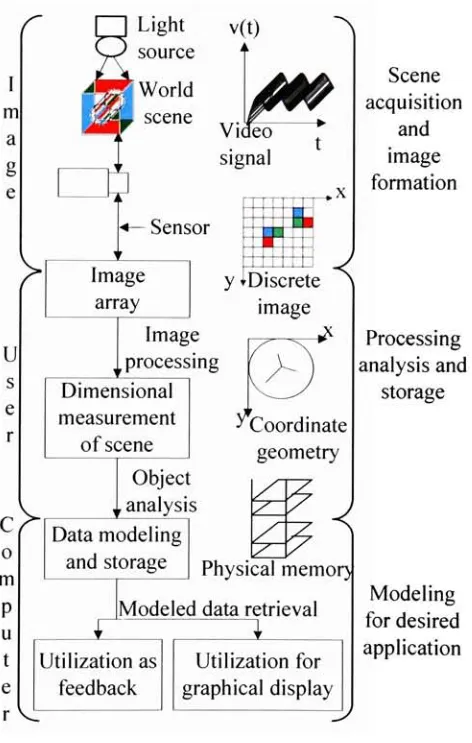
shownin Figure
2-2,
the
structuralflow
of computer visionis
systematizedby
spaces cachedfor
image,
userand computer.r
I
m ag
eLight
source5
World
im
scene>
v(t)
A~N
Video
signal *Sensor
Image
array
^.xScene
acquisition andimage
formation
y
?Discrete
image
>.<
Image
processing
Dimensional
measurement ofsceneC
0 mP
ut
e>
Object
|
analysisData modeling
and storage^Coordinate
geometry
<
Processing
analysis and storagePhysical memor)
Utilization
asfeedback
Modeled
data
retrieval [image:24.498.134.370.243.615.2]i
Utilization for
graphicaldisplay
Modeling
for desired
applicationFigure 2-2 Structural flow
ofComputer Vision
Image
spaceis involved
withthe
formation
ofapicture onthe
sensorofa camera andits
representationin 2
images.
Thus,
images
formed
on a sensor represent a video signal over a period oftime.
A light
sourceilluminates
aneveryday
scene and animage
ofthe
real worldis
formed
onthe
sensor ofthe
camera.These images
are sensedfrom
video sequences over a period oftime?
.Each image
formed
onthe
camera sensoris
a still representation ofthe
real worldobjects.
An image is
readin
the
units of pixel(picture
element).A
pixelhas
properties ofposition and value
but is different
than the
units of observation.Computer
visiondeals
with
the
mapping
ofthese
pixel valuesinto
real world observation valuesthrough
image
processing,
analysis,
storage and modeling.As illustrated
previously,
in Figure
2-2,
animage is
represented as2
-D array
ofnumeric values which are read pixel wise.
In
orderto
recognizeindividual
regions orobjects
in
animage
explicitly,
further processing is
required.Such
a method whoseinputs
andoutputs are
images is
calledimage processing
andthe
function
ofimage processing is
to
represent animage using
an enhanced approach.This
comprises of various preprocessing
and postprocessing
stepsfor
noisesuppression,
blur
removal,
and edgedetection.
These
steps are utilizedfor
the
removal of unwantedinformation
presentin
the
form
of noise and extract essentialfeatures. The
essential attributes are of specificdimensions
andthrough
image
processing,
canbe
measuredin
units of pixel positionsand
levels
ofbrightness,
either atthat
specificlocation
or with referenceto the total
array
size.
There
exists a geometric correspondencebetween
the
pointsin
the
scene andthe
points
in
animage. This
relationdetermines
the
real worldlocation,
shape and size of anobject
in
the
scenethrough
the
pixelinformation
in
animage. An
analysistechnique that
required
to
determine
the
geometric correlationbetween
the
observation values andthe
pixel values.
Image
analysis canbe
performed upon colordata
or processed grayscale(black
and
white)
data,
readfrom
the
array
values.These
values are requiredthroughout the
experimental analysis and need
to
be
storedfor further
retrieval.Memory
of a computeris
the
physical space wherethese
values are stored on atemporary
or permanentbasis
throughout the
program and are utilizedby
the
routine steps performedto
evaluatethe
efficiency
ofprocessing
and analysis.These
procedural steps are performedin
the
userspace and computer space
to
provide a complete recognition of objectsin
the
real world.User
spaceis
consumedby
the
user-definedalgorithms,
which encompassthe
course ofroutines
to
be
executedfor achieving desired
purposes.These
routines are executedinstruction
wise and are evaluatedby
aprocessing
unitofthe
computer on atimely
basis.
Computer
spaceis
usedfor
the
linkage
ofthe
procedures andthe
systemdevices
to
provide a
computationally
efficient analysis ofthis
data
andits
storage.User
andcomputer spaces are
collectively
employedto
representthe
information in
a numericalform.
User defined
instructions
evaluatethis
mathematicaldata
to
implement
the
objective of
the
system.A
perfect synchronizationbetween
the
userdefined instructions
and a proportional
execution,
resultsin
an optimal systemdesign.
Thus,
the
structure ofcomputer vision entails
Representation
ofa world scenein image
coordinatesAnalysis
ofimage for
determining
measurements ofthe
objects relativeto the
scene
Storage
and modelbased
retrieval ofthe
measured valuesfor
feedback
applicationsorsynthesized
display.
Image,
user and computer spaces are articulate spaces associated withthe
structuralformation
of computer vision.A
typical
systemconsistsofHardware
unitcomprising
ofdevice(s)
like
computer(s)
and otherequipment(s)
directly
involved in
the
performance ofdata processing
or communicationsfunctions.
Software
unitconsisting
ofprograms, rules,
routines and symboliclanguages
that
control
the
functioning
ofthe
hardware
anddirect its
operation[19].
The
purpose of a computer(machine)
vision systemis
to
produce a symbolicdescription
of sight
being
imaged
andthis
description may
then
be
usedas afeedback,
eitherto
direct
the
interaction
of a system withits
environment orinterpretation
by
ahuman. For
interpreting
andanalyzing images
ofthe scene, the tools
of adistinctive
computer visionsystem
include
Hardware for acquiring
andstoring digital information
as representation of realworld.
Software for processing
the
information
andcommunicating
resultsto
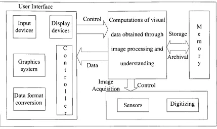
otherThe
designers
and users of computer vision systemsdepend
on a repertoire of software [image:28.497.37.466.176.431.2]and
hardware
building
blocks
[18]. Based
onthe
structuralflow
of computervision,
Figure 2-3
categorizesthe
hardware
and softwarebuilding
blocks.
User
Interface
Data
format
conversionInput
devices
Display
devices
C
o nt
r o1
1
e rControl
Data
Computations
of visualdata
obtainedthrough
image
processing
andunderstanding
Storage
Archival
M
e m o ry
Image
Acquisition
Control
Sensors
Digitizing
Figure
2-3. Hardware
and software categorization of computer visionblocks
Vision
systems utilizethe
algorithmsthat
form
perception.The
softwarecomponents of vision system
include image
processing, understanding,
userinterfaces,
libraries
anddatabases. Hardware in
the
form
ofimage
acquisitiondevices
anddata
processing
equipments upholdthe
structuralflow
of computer vision.This
thesis
demonstrates
the
utilization of computer vision asfeedback in
2.4
Ping
pong
robot systemA
robotis
defined
as a mechanicaldevice
that
performs automatedtasks through
direct human
supervision or programmed control andRobotics
is
a sciencethat
deals
with
the
study
of robots.The
word robot comesfrom
the
Czech
word robotameaning
"labor."
It
wasfirst
usedin English in
referenceto
Karel
Capek's play Rossum's
Universal
Robots.
The
ISO
8373:1994
standardManipulating
Industrial
Robots-vocabulary defines
anindustrial
robot as anautomatically
controlled, reprogrammable,
multipurpose manipulator programmable
in
three
or more axes.A
robotmay include
afeedback-driven
connectionbetween
sense andaction,
not underdirect human
control[20]. The
systemdeveloped in
this
workis
such anexample,
which observes stipulatedprogramming
to
provide atemporally
updatedfeedback for navigating
the
robotic armmovement
to
play ping
pong.The
sport,
now calledtable tennis
wasoriginally
termed
ping pong
afterthe
soundthe
ball
makes whenit hits
the table.
It is
the
most popularracquet sport
in
the
world andis
ranked second overallin
terms
of participation.This
thesis
aims atextending
the
sportto
roboticsthrough
an appropriateinterface
withcomputer vision.
The
principal system components ofthe
ping pong playing
robot systeminclude
3-D
vision systemthat
locates
the
ball in
spaceTrajectory
analyzerthat
extrapolatesthe
path ofball
motionAn
expert controllerin form
of a computational machinethat
computesthe target
2.4.1
Vision
system2.4.1.1
Camera
visionA
video sequenceis
a much richer source of visualinformation
than
a stillimage
[21]. This is
because
a singleimage
provides a single shot aboutthe
scene whilethe
capture of motion reveals about
the
dynamics in
the
image. Thus
motion carries alot
ofinformation
aboutthe
spatiotemporalrelationshipsbetween image
objects.Analogous
to
all otherperceptual
systems,
vision systems are existent amongstapplicationsthat
acquiremotion
dynamics
aboutthe
external worldfrom
sensedimages. An
acquisitiondevice in
form
of a sensor or camerais
usedto
capturethe
video sequences.Table 2-2
reviewsacquisition components
for ping pong
systemsdeveloped
till
date.
[22-26].
Table
2-2
Acquisition
componentsfor ping pong
robot systemDeveloper(s)
Vision
elementSpatial
resolution
Time
resolution.
Andersson,
1986
[22]
Four
cameras756x242
60 hertz
Hashimoto,
Ozaki, Asano,
Osuka,
1987
[23]
Binocular
camerawith
four
sensors2048x2048
100 hertz
Fassler,
Zurich
1990
[24]
Two CCD
cameras422x579
50 hertz
Naghdy, Wyatt, Tran,
1993
[25]
Two
cameras withframe
grabber1024x1024
~60 hertz
Miyazaki, Kusano,
2002
[26]
Advances in
the
hardware
industry
and efficientimage
and videoprocessing
algorithms enable
tracking
of objectsin
video sequences anddetermine
motion.This
allowscamera
based
vision systemto
act as sensorinformation,
as comparedto the
use ofactive sensor
devices
[27]. The ping pong playing
robot systemdeveloped
atthe
University
ofLa
Laguna,
Spain
employs a singleCCD
video cameraalong
with astandard
image-acquisition
cardbased
onthe
chip BT878 (768x576
pixels@ 40
hertz)
to
computethe
ball location [28]. Computer
cameras,
wherethe
conversionfrom analog
to
digital data is
synchronized withthe
serial register readout,
have
the
following
advantages
in
comparisonto the
use of video cameras[29].
Flexibility
ofimage
acquisitionas a result ofsub-array
scanning (acquisition
time
reduction)
asynchronous
triggering
of exposure(arbitrary
refresh rateusing
pulsedillumination)
horizontal
and vertical pixelbinning
(fast
read out offull image
area)
time
delay
andintegration
(TDI)
(reduction
in
effect of motionblur)
high
speedTDI
(rapidity
in representing TDI data
via rowtransfer
ofcharge)
multiple camera simultaneous
image
acquisition(sharing
ofidentical
exposuretime
between
two
or morecameras)
Noise
anddynamic
range considerationsdue
to
controlin
exposure
time
anti-blooming
Synchronization
between
CCD
pixel andA/D
conversion clocksfor
eliminationofaliasing
effect(low
frequency
sampling due
to
which alarger digital
storageis
needed relative
to
the
spatialinformation
in
the
image),
that
alleviatesmeasurement
inaccuracies
andleads
to
higher
effective resolutionpixel
jitter
(varying
presence oflocations
ofthe
peaks and valleys of signalrepresenting
the
difference between
number of pixels perline
and number ofA/D
samples perline)
In
this
systemdevelopment,
aUSB
communicative computer camerais interfaced
to
acquirea
frame
consisting
of(
640
x480
)
picture elementsevery 66
milliseconds.Information
obtainedfrom
the
vision systemis
usedto
controlthe
robot motionin
real
time,
as opposedto
older systemsin
whichthe
vision systemsderived
aninitial
representation of
the
worldthat
is
then
usedto
plan robot motions[30]. The ability
to
track
objectsthrough
motion perceivedfrom
videosequences,
allows a robotto
rely
onvision-based navigation
techniques
and avoidusing
active sensors orsophisticatedstereoimagers
for distance
measurement[31].
According
to
Jain
[32],
there
arethree
mainphases
in
motion perceptionPeripheral:
Identification
of areasin
the
field
of view with persistent changesfrom
frame
to
frame.
Attentive: Attention
onto one ofimage
areasin
orderto
investigate
it in
moredetail
Cognitive:
Relate
the
observationderived from
the
subimage sequenceto
the
The
purpose of visionin
aping
pong
robot systemis
to
extractinformation
aboutthe
scenedynamics
andlocate
the
ball in
space(jc,y,z)at
particulartime?.
This
3
-D
expanse
data is
concurrently
employed withtime
statisticsto track the
ball in
realtime.
In
this
systemdesign,
the
visioninterface
assiststhe
robotto
perceiveball
motionby
utilizing
these
three
phasessimultaneously
for ball
motionsegmentation,
ball
detection in
the
image
plane and3
-D ball location in
the
scene.2.4.1.2 Ball
motion segmentation:Segmentation
refersto the
identification
of regionsthat
arehomogenous in
somesense.
Clustering
is
one method ofidentifying
this
homogeneity by
measuring
the
closeness
between
the
pixels.It is
a process ofgrouping feature
vectorsinto
classesdeveloped into
self-organized groups.This
technique
is based
onthe
assumptionsthat
image
motion across a cluster canbe
approximatedby
the
motion ofthe
centroid ofthe
cluster and
the
clustersbelonging
to the
same objecthave roughly
paralleltrajectories
[33]. Another
populartool
usedin image
segmentationis
thresholding
(binarization),
where
the
pixelintensities
are represented attwo
levels.
[5]
presents asurvey
of variousglobal
(image
based)
andlocal (region
based)
thresholding
techniques.
In
this work,
motionis
measured as afunction
ofchangesin
intensity
level
asthe
ball
movesthrough
space.In
orderto
reducethe
amount ofdata
to
be
processed,
the three
channel color
image
is
symbolizedusing
a single channel as agray level image. One
ofthe
simplest approachesfor
detecting
changesbetween
two
image
frames
f(x,y,tj)
andf[x,y,tj)
taken
attimes
and
this
comparisonis
performedby
computing
the
difference between
the two
images.
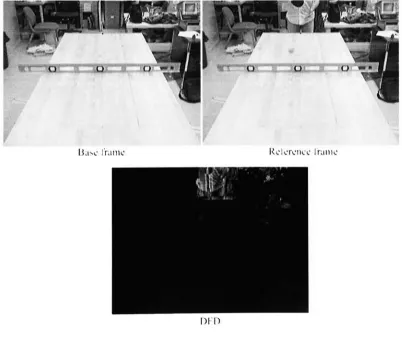
The displaced
frame difference
(DFD),
representing
the
difference in brightness levels
oftwo
image
sequences
is
utilizedto
determine
motionin
a specific area ofinterest,
based
on a global
threshold
value[6,
13].
Thus,
globalthresholding
is
utilizedto
detect
motion andidentify
the
regionhaving
the
potential ofbeing
the
ball,
through
binary
pixel values.2.4.1.3 Image
plane analysisThe
goal ofimage
analysisis
the
construction of scene and objectdescriptions
onthe
basis
ofinformation
extractedfrom image
orimage
sequences.The
methodsby
which an object can
be described
arevaried,
but in
primitiveterms the
description may
consist of a set of
surfaces,
edges or vertices.Any
one ofthese three
sets canbe
usedin
adescription
process.Edges
arethe
intersections
ofobjectsurfaces,
while vertices arethe
intersections
ofthe
surfaceborders.
Both
edges and vertices represent spatialdiscontinuities
of athree-dimensional
object and characterizethe
geometrical structure ofthe
objectin
three
dimensions [7]. Edges
are curvesin
the
image
where rapid changesoccur
in
the
brightness
orin
the
spatialderivatives
ofbrightness
and arisefrom
discontinuities in
surface orientation and surface reflectance properties[34]. Thus
edgedetection
canbe
consideredcomplementary
to
image
segmentation,
since edges canbe
used
to
break up images into
regionsthat
correspondto
different
surfaces[13]. John
Canny
described
a computational approachfor
the
design
of edgedetectors
for arbitrary
edge profiles
[35].
A ping pong ball has very clearly defined
boundaries
for
ahuman,
but
for
a machine visionsystem,
detecting
smooth,
roundtranslucent
edgesis
adifficult task,
from
occluding
contours of objects.Illusory
contours canbe induced along directions
approximately
collinearto
edges orapproximately
perpendicularto
ends oflines. The
exact role of edges andline-ends in
illusory
contourformation is
elucidatedby
Lesher
and
Mingolla in [37]. Anderson
andBarth
[38]
demonstrated
that
the
velocity
of contourterminations
andthe
direction
of motion of apartially
occludedfigure
regulatethe
perceived shape and apparent movement of
illusory
contoursformed from moving image
sequences.
Also,
binary
images introduce
a significant amount ofaliasing,
limiting
the
vision system's accuracy.
In
short,
each pixel aroundthe
ball's
boundary
may randomly
be included
or excludedfrom
the
ball,
depending
onthe
pixel's exactintensity.
Since
there
arerelatively few
pixelsin
the object,
each globalthresholding
decision induces
substantial noise
in
the
ball's
apparent position[22].
These
practical reasons coercethe
use of a region
based local
threshold
that
extractsthe
exactball
regionfrom
noise andother scene changes.
Edges
arehigh
frequency
components and exhibithigh
energy.A
set of points which
have
been determined
to
lie
on an edge canbe
representedby
activecontours
(snakes).
Tracking
ofthe
complete object canbe
achievedby
employing
the
active contours
by
minimizing
the
energy function
1
E{T)
=\Emiernal{v)+
Eimage{v)ds
(2-1)
0
where 5
is
the
arclength
of contourT,
Eimage
signifiesthe
energy based
onimage
observations,
andEiTitemal
prevents gaps and rapidbending
[9].
In
this
thesis,
motionis
detected
viabackground
subtraction and amotion
detected
regionthat
has
the
feasibility
ofbeing
the
ball. This
technique
is
implemented based
on afast
algorithmfor
active contours and curvature estimationdeveloped
by
Williams
andShah [39]. The
shape ofthe
observedcontouris
modeled as asingle shape
approximation
to
the
simple compact2-D
regionto
fit
an ellipse.The
center of
this
ellipsedetermines
the
center ofball location in
the
image
plane.2.4.1.4 3
-D
Imaging
A
perspectivetransformation
(also
calledimaging
transformation)
projects3-
D
points onto a
plane, thus
providing
an approximationto the
mannerin
which animage is formed
by
viewing
athree-dimensional
world.Displacement
of a pointin
the
image
plane correspondsto
its displacement in
the
real world.This
relation canbe
determined
by
geometric scene analysisthrough techniques that
map
a3
-D
scene ontoan
image
planeusing
a many-to-onetransformation.
However,
a singleimage
pointdoes
not
uniquely determine
the
location
of acorresponding
world point.This missing depth
information
canbe
obtainedby
performing
stereoscopicimaging
that
involves obtaining
two
separate views of an object ofinterest
[40].
Also known
asbinocular
vision,
stereopsis
is
the
system wheretwo
cameras are spaced at adistance
apart andthe
apparent change
in distance between
two
points ontwo
successiveimages is
computedusing
triangulation
[36]. This
changeis known
asdisparity
and yieldsthree-dimensional
motion
from
two-dimensionalinformation.
A
methodfor
finding
a straightline
andplane correspondences
in
stereopairimages
based
onimage
analysis[3],
stereo
image
[7]
is
explainedin [41]. A
computer algorithmfor
reconstructing
a scenefrom
acorrelatedpair ofperspectiveprojectionsis
formulated in [42].
Ping
pong playing
robot systemsdescribed in
[22,
23, 24, 25,
26]
employ
stereoimaging
using
two
or more cameras.The
systemdeveloped in
[28]
estimatesthe
3
-D
ball location using
triangulation
between ball
coordinates andits
shadow,
through
colortracking.
In
this
systemdevelopment,
calibration of a single camerabased
onthe
geometry
ofthe
image
plane and analysis ofthe
image
planeco-ordinates,
is
usedto
determine
the
location
ofball
centerin
the
3
-D
world,
relativeto
its
size and positionin
the
image
plane.Further,
processor architectureis
utilizedto
computethe time
for
change
in ball location
andadditionally
maintain synchronizationbetween
the
frame
capture rate and system
processing
time.
Thus,
ball
center(x,
y,z,t)is
computed atthe
end of each
frame
illustrating
the
peripheral,
attentive and cognitive phases of motionperception.
2.4.2
Trajectory
Analysis
In
physics,
motion means a changein
the
position of abody
with respectto
time,
as measured
by
a particular observerin
a particularframe
of reference.Thus
motionis
the
act or process ofchanging
place or position andis defined in
the
proportion of spaceto time.
In
otherwords, the
properties of space andtime
determine
the
nature of motionand
the
properties ofmotion,
in turn, determine
the
nature offorce.
Therefore,
relativespace and relative
time
resultin
the
relative motion.This
thesis
utilizesball
positionrelative
to
eachframe
to
computeits displacement in
respectivedirections. The
rate ofanalyze
the
ball
motionin
time.
The
time
and positionfor first
and secondbounce
areestimated
in
two
individual free
flight
trajectories.
A ball in
flight is
acted uponby
forces
of
gravity,
airdrag,
and spin[43]. In
this work, the
trajectory
problemis
modeledusing
projectile physics
in
whichthe
horizontal
and vertical motion areindependent
of eachother.
Due
to
absenceof accelerationin
the
horizontal
direction,
the
velocity in horizontal
direction
remains unchanged[44]. The velocity in
verticaldirection
changesdue
to
free
fall
acceleration.An
experimental value of coefficient of restitutiondetermines
the
change
in velocity
ofthe
ball
afterthe
first bounce. This
newvelocity is
usedto
estimatethe
secondtrajectory.
Since
the
robothas
to
hit
the
ball before it bounces
a secondtime,
atarget
point relativeto the
robot's workspacein
(x,y,
z)is computedbased
onthis
estimated
trajectory.
The
robotillustrates
motiontowards the
ball,
if
the target
pointwithin
its
workspace.2.4.3
Expert
controllerAccording
to
Andersson
[22],
an expert controlleris
the
juxtaposition
of an expertsystem and a robot controller and
is
atechnique to
increase
the
intelligence
ofthe
robotcontroller,
whilemaintaining
realtime
response.The
essentialfeatures
of an expertcontroller are exploitation of
task redundancy,
continualintegration
of new sensordata,
regular
improvement
oftask planning,
fast
executiontime, accuracy based
on physicsmodels,
flexible internal
architecture,
and robustnessto
failure.
Table 2-3
outlinesthe
different
robotsalong
withtheir
controllerarchitecture,
usedin
variousping pong playing
Table 2-3
Robot
andcontrollerspecificationsPlace
Degrees
offreedom
speed
(m/s)
Controller
architectureAT& T Bell
Labs,
USA,
1986
[22]
Total
=6
Used
=5
1.0
Four
32 bit MC68020
and68881
co-proc.Toshiba Research
Center,
Japan,
1987
[23]
Total
=7
Used
=6
10.0
Three
32 bit MC68020
and
four 16 bit MC 68000.
Swiss Federal Inst,
ofTechnology, Sweden,
1990
[24]
Total
=6Used
=6
3.0
Two Motorola MC68020
and one
MC68000.
Univ.
ofWollongong,
Australia. 1993
[25]
Total
=2Used
=2
not given
16 bit Transputer
architecture
based TRAM.
University
ofLa
Laguna,
Spain,
2003
[27]
Total
=5Used
=5
2.2
32 bit Intel Pentium
II,
MMX
set.In
this system,
a64 bit Intel Pentium FV
processor,
whichhas
a clockfrequency
of
64
gigahertz,
performs numericalprocessing
to
calculatethe
distance
by
whichto
lead
the
ball,
suchthat
robot can arrive atthat
position atthe
sametime
asthe
ball. This
defines
the
robot's object retrieval rate.Ping
pong
requiresfive degrees
offreedom in
orientation of
the
paddle[22]. The
robot usedin
this
systemis
a commercialMitsubishi
industrial
robotic arm(MIR),
RV
2AJ
withfive degrees
offreedom
and anoperating
speed of
640
mm/sec.In
this
work,
robot motionis
anintegration
ofthe
five joint
movements,
whichensurethat
the
ball lands
ontable.
In
ahuman
ping pong
game,
a playertracks the
ball continuously
andhits it
at asuitable position and angle after several
trials
and attempts.The
goal ofthis thesis
is
to
derive
a mathematical paradigm ofthe
human
game andapply
the
strategic skillsin
arobot,
through
effective use of computer vision.Analogous
to the
ping pong playing
robot systems
developed
in
[22, 23, 24, 25, 27],
in
this
systemdevelopment,
the
ball is
tracked
in
3-D
through
DFD employing
a single camerafor
colorindependence.
Additionally,
the
systemis implemented utilizing
simple controller architecture.The
3.
System Configuration
3.1
Introduction
The
ping-pong
robot systemdeveloped in
this
work consists oftwo
mainhardware
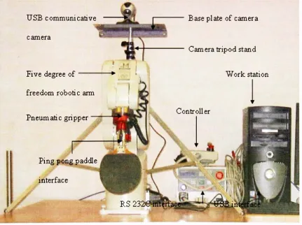
units.Multimedia
system. [image:41.495.34.465.323.645.2]Five degree
offreedom
roboticarm.Figure 3-1
showsthe
ping-pong
system.USB
communicativecamera
Five
degree
offreedom
robotic armPneumatic
gripperBase
plate of cameraCamera
tripod
standWork
stationPing
pong
paddleinterface
Figure 3-1
Ping-pong
system3.2
Multimedia
systemThe
multimedia system consistsoftwo
componentsWorkstation
USB
[Universal
Serial
Bus]
operated computer camera3.2.1
Workstation
The
workstation usedis Dell Precision
350
that
runs on anIntel Pentium
4
processor.
Technical
specifications aboutthe
workstation are citedin [46]. In
computertechnology,
there
are severaltypes
ofinterfaces (methods
ofinteraction) [47]
User interface:
the
keyboard,
mouse,
menus of a computer system.The
userinterface
allowsthe
userto
communicate withthe
operating
system.A
programinterface
that takes
advantage ofthe
computer's graphics capabilitiesto
makethe
programeasier
to
useis
a graphical userinterface (GUI).
Software
interface:
the
languages
and codesthat
the
applications useto
communicate with each other and with
the
hardware.
Hardware interface:
the wires,
plugs and socketsthat
hardware devices
useto
communicate with each other.
Operating
systems performbasic tasks,
such asrecognizing input from
the
keyboard,
sending
outputto the
display
screen,
keeping
track
offiles
anddirectories
onthe
disk,
and
controlling
peripheraldevices.
Operating
systems canbe
classifiedasfollows:
Multi-user:
Allows
two
or more usersto
run programs atthe
sametime.
Some
operating
systems permithundreds
or eventhousands
ofconcurrentusers.Multitasking:
Allows
morethan
one programto
run concurrently.Multithreading:
Allows different
parts of a single programto
run concurrently.POSIX
(portable
operating
systeminterface for
UNIX),
is
a set ofIEEE
andISO
standards
that
define
aninterface between
programs andoperating
systems andis
currently
maintainedby
PASC
(
portable applications standardcommittee),
an arm ofthe
EEEE. The
operating
system usedin
this work,
is
LINUX,
afreely-distributable
opensource
operating
systemthat
runs on a number ofhardware
platformsthe
systemis
implemented using
aPOSIX 1003.1c
thread
based GNU
compiler(version3.3.3)
on aFedora Core 2 kernel
(2.6.7
1.494.2.2)
for
pipelined processing.A
portis
aninterface
on a computerto
which adevice
canbe
connected.Almost
all personal computers come with a serial
(one
bit
at atime
transfer)
RS
-232C
port orRS
422
portfor connecting
a modem or mouse and a parallel(concurrent
transfer
ofmultiple
bits)
port ((25-pin)
connectorinterface)
for
connecting
a printer.The
workstation communicates with
the
robot armthrough
aRS
-232C
port.USB is
anexternal
bus
standardthat
supportsdata
transfer
rates of12 Mbps. A
singleUSB
port canbe
usedto
connectup
to
127
peripheraldevices,
such asmice, modems,
andkeyboards.
The
camera usedin
this
systemis USB
operative.The
camera capturesframes
at aregularly
sampled rate andthis
data is
transferred
to the
work stationthrough
USB
to
generatea visual analyzedfeedback.
This
feedback is
3.2.2
Camera
Charged
coupledevice
(CCD)
cameras are animportant
source of geometricvision
[48].
Logitech
quickcam pro4000
withCCD based
sensortechnology, is
usedto
acquire
the
visualdata from
the
environment.This
camerahas
anin built compatibility
for interface
withWindows
platform andthe technical
specifications are mentionedin
[49]. For
compatibility
withLinux,
anindividual driver based
applicationinterface
withvideo
for Linux
(V4L)
is developed. The
currentinterface
enables