Design and Implementation of a Wireless Gesture
Controlled Robotic Arm with Vision
Love Aggarwal
Varnika Gaur
Puneet Verma
B.Tech (ECE), GGSIPU B.Tech (ECE), GGSIPU B.Tech (ECE), GGSIPUABSTRACT
In today’s world, in almost all sectors, most of the work is done by robots or robotic arm having different number of degree of freedoms (DOF’s) as per the requirement.
This paper deals with the Design and Implementation of a “Wireless Gesture Controlled Robotic Arm with Vision”. The system design is divided into 3 parts namely: Accelerometer Part, Robotic Arm and Platform. It is basically an Accelerometer based system which controls a Robotic Arm wirelessly using a, small and low-cost, 3-axis (DOF’s) accelerometer via RF signals. The Robotic Arm is mounted over a movable platform which is also controlled wirelessly by another accelerometer.
One accelerometer is mounted / attached on the human hand, capturing its behaviour (gestures and postures) and thus the robotic arm moves accordingly and the other accelerometer is mounted on any of the leg of the user / operator, capturing its gestures and postures and thus the platform moves accordingly. In a nutshell, the robotic arm and platform is synchronised with the gestures and postures of the hand and leg of the user / operator, respectively. The different motions performed by robotic arm are: PICK and PLACE / DROP, RAISING and LOWERING the objects. Also, the motions performed by the platform are: FORWARD, BACKWARD, RIGHT and LEFT. The system is equipped with an IP based camera also which can stream real time video wirelessly to any Internet enabled device such as Mobile Phone, Laptop, etc.
Keywords:
Accelerometer, DOF, IP, RF Module1. INTRODUCTION
A robotic arm is a robot manipulator, which can perform similar functions to a human arm.
Robotic arms are the vital part of almost all the industries. In industries, a robotic arm perform various different tasks such as welding, trimming, picking and placing etc. Moreover the biggest advantage of these arms is that it can work in hazardous areas and also in the areas which cannot be accessed by human. For example in NASA’s mission to Mars, the Spirit and Opportunity drone. It is also used to implement highly precise medical treatments etc.
Many variants of these robots/robotic are available or designed as per the requirement. Few variants are Keypad Controlled, Voice Control, Gesture Control, etc. However, most of the industrial robots are still programmed using the typical teaching process which is still a tedious and time-consuming task that requires technical expertise. Therefore, there is a need for new and easier ways for programming the robots.
In this paper, the gesture based system (using Accelerometer) [1] [2]
has been incorporated to control the robotic arm as well as its platform using two, small and low-cost, 3-axis accelerometers. The prime aim of the design is that the robot and platform starts the movement as soon as the operator makes a gesture or posture or any motion. The Robotic arm is synchronized with the gestures (hand postures) of the operator and the platform part is synchronized with the gestures (leg postures) of the operator.
The goal of this paper is to develop methodologies that help users to control and program a robot, with a high-level of abstraction from the robot specific language i.e. to simplify the robot programming.
2. RELATED WORK
Today, there are a number of robotic arms used in robotics research, many with unique features and design criteria. In this section, brief of some recent widely-used and/or Influential robotic arms is given.
In the robotics field, several research efforts have been directed towards recognizing human gestures.
Few popular systems are:
2.1 Vision-based Gesture Recognition
[3]This Recognition system basically worked in the field of Service Robotics and the researchers finally designed a Robot performing the cleaning task. They designed a gesture-based interface to control a mobile robot equipped with a manipulator. The interface uses a camera to track a person and recognize gestures involving arm motion. A fast, adaptive tracking algorithm enables the robot to track and follow a person reliably through office environments with changing lighting conditions. Two gesture recognition methods i.e. a template based approach and a neural based approach were compared and combined with the Viterbi algorithm for the recognition of gestures defined through arm motion. It results in an interactive clean-up task, where the user guides the robot to go to the specific locations that need to be cleaned and also instructs the robot to pick up trash.
2.2 Motion Capture Sensor Recognition
[4]40
2.3 Finger Gesture Recognition System
based on Active Tracking Mechanisms
[5]The prime aim of the system (based on the above mentioned recognition methodology) proposed by the author is to make it feasible to interact with a portable device or a computer through the recognition of finger gestures. Apart from the gestures, speech can also be other mode of interaction because of which this system can form part of a so-called Perceptual User Interface (PUI). The system could be used for Virtual Reality or Augmented Reality systems.
2.4 Accelerometer-based Gesture
Recognition
This Gesture Recognition methodology has become increasingly popular in a very short span of time. The low-moderate cost and relative small size of the accelerometers are the two factors that makes it an effective tool to detect and recognize human body gestures.
Several studies have been conducted on the recognition of gestures from acceleration data using Artificial Neural Networks (ANNs) [6] [7] [8].
3. TECHNICAL REQUIREMENTS
The technical requirements chosen as a basis for the efficient functioning of the system are as follows:
3.1 Microcontroller
ATmega 328 microcontroller is used as the hardware platform. It is the controlling unit, to which all other components (Accelerometers, Motors, RF modules etc.) are interfaced. Two such microcontrollers are used in this project, one at the Transmitting end and one at the Receiving end.
3.2 RF Module
RF stands for Radio Frequency. This module consists of further two parts: Transmitter (Tx) and Receiver (Rx). It is available in different operating frequencies with different operating range. An Encoder Circuit and a Decoder Circuit is used along with the Transmitter and Receiver respectively in order to transmit and receive the message/signal [9].
The native communication task between the Robotic Arm, Platform and the different hand and leg gestures of the user is done by this module via RF signals. One such RF Module is required in this project. The RF Module used in this project works on the frequency of 315MHz with an operating range of 400-500 metres.
3.3 Accelerometer
[10]An accelerometer measures gravitational force or acceleration. By tilting an accelerometer along its measured axis, one can read the gravitational force relative to the amount of tilt. Most accelerometers available today are small surface mount components, so you can easily interface them to a microcontroller. There are three axes that can be measured by an accelerometer and they are labelled as X, Y and Z. Each measured axis represents a separate Degree of Freedom (DOF) from the sensor—thus a triple axis accelerometer might be labelled as 3 DOF. In this project, only 2 axes namely X and Y are used. The accelerometer used in this paper is ADXL3xx [11].
3.4 Camera
[12]The system uses a smartphone with camera for continuous real time video streaming of the system and its surroundings. An
IP-based Android application [13], running on the smartphone enables the system to transmit the real time video wirelessly.
4. OVERALL DESIGN OF THE SYSTEM
In this paper, a robotic arm with three degrees of freedom is designed, which is able to pick the desired object and place them at the desired location.
Based on functionality, the system has been categorised into the following parts:-
Robotic arm Platform
Communication system Wireless Video Transmission
4.1 Robotic Arm
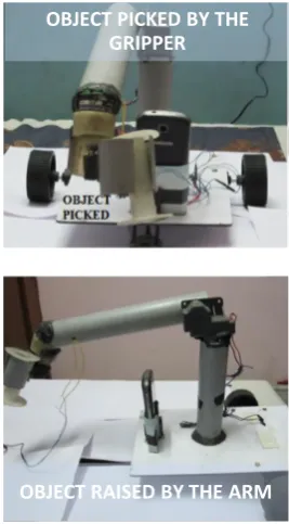
This is the vital part of the system as it is this part which does the Pick and Drop task of the project. The robotic arm is equipped with a Gripper (for picking and placing the objects) and an Arm (for raising and lowering the objects), shown in Figure 1 and Figure 2. Both the Arm and Gripper are equipped with Servo Motor to control the movement. These movements are synchronised with the hand gestures of the user, operating the Robotic Arm. The accelerometer mounted on hand, which captures the hand gestures, is shown in Figure 3. Also, the different hand gestures, shown in Figure 4, are described below: GESTURE 1: To Lower the Arm
GESTURE 2: To Raise the Arm
GESTURE 3: To close the Gripper Mouth so that it can pick the object
[image:2.595.309.550.466.704.2]GESTURE 4: To open the Gripper Mouth so that it can place / drop the object
Figure 2: Arm and Gripper in action
Figure 3: Accelerometer mounted on Hand
Figure 4: Different hand gestures to control the Robotic Arm (Arm & Gripper) Movement
4.2 Platform
Platform is nothing but that part of the project onto which the Robotic Arm is mounted. The platform is fitted with DC Motors and its movement is synchronised with the leg gestures of the user, operating the Robotic Arm. The accelerometer mounted on any one of the user’s leg, which captures the leg gestures, is shown in Figure 5. Also, the different leg gestures which results in the movement of the platform, shown in Figure 6, are described below. It is this part of the project which takes the entire project from one place to another.
GESTURE 1: To make the platform move in Forward direction GESTURE 2: To make the platform move in Backward direction
GESTURE 3: To make the platform take a turn towards Right GESTURE 4: To make the platform take a turn towards Left
Figure 5: Accelerometer mounted on leg
Figure 6: Different leg gestures to control the platform movement
OBJECT PICKED BY THE GRIPPER
OBJECT RAISED BY THE ARM
GESTURE 1
GESTURE 2
GESTURE 3
GESTURE 4
GESTURE 1
GESTURE 2
GESTURE 3
GESTURE 4
[image:3.595.324.530.532.713.2] [image:3.595.65.279.533.717.2]42
4.3 Communication System
[image:4.595.318.513.74.345.2]This part is the heart of the entire project. Without an effective and reliable communication system, no system / project can work. Similar is the case with this project also. The RF Module, details of which are mentioned under Section 3.2, is the only communication equipment required in this project. This Module is used to transmit the different hand and leg gestures made by the user (encoded in the form of 4-bit digital data) wirelessly to the receiver [14], which decodes the received 4-bit digital data and according to which the arm, gripper and platform moves. The block diagrams shown in Figure 7 & Figure 8 depicts the entire communication system of the project. The Linker (Circle, named “A”) in Figure 7 and Figure 8 is used to show the connection (flow of signals) between the Transmitter End and the Receiver End.
Figure 7: Block diagram of Transmitter End
Figure 8: Block Diagram of Receiver End
4.4 Wireless Video Transmission
An IP based camera has been integrated with this system for real time video streaming. The video captured by the camera is transmitted over the internet and it can be viewed on any internet enabled device (Mobile Phone or Laptop) by entering the IP address, in the URL bar, provided by the IP based Camera.
5. REFRENCES
[1] Pedro Neto, J. Norberto Pires, A. Paulo Moreira, “Accelerometer-Based Control of an Industrial Robotic
Arm” Available at:
http://arxiv.org/ftp/arxiv/papers/1309/1309.2090.pdf
[2] Dr. R. V. Dharaskar, S. A. Chhabria, Sandeep Ganorkar, “Robotic Arm Control Using Gesture and Voice”, In International Journal of Computer, Information Technology & Bioinformatics (IJCITB), Vol. 1, Issue 1, pp. 41-46 Available at: http://www.ijcitb.com/issues/paper_9.pdf
[3] S. Waldherr, R. Romero and S. Thrun, 2000, “A gesture based interface for human-robot interaction”, In Autonomous Robots in Springer, vol. 9, Issue 2, pp.
151-173Available at
http://www.cs.cmu.edu/~thrun/papers/waldherr.gestures-journal.pdf
[4] K. Brahmani, K. S. Roy, Mahaboob Ali, April 2013, “Arm 7 Based Robotic Arm Control by Electronic Gesture Recognition Unit Using Mems”, International Journal of Engineering Trends and Technology, Vol. 4 Issue 4 Available at: http://www.ijettjournal.org/volume-4/issue-4/IJETT-V4I4P347.pdf
ACCELEROMETER 1 (Mounted on hand)
MICROCONTROLLER (ATmega 328)
TRANSMITTER (RF) ACCELEROMETER 2 (Mounted on leg)
A
A
RECEIVER (RF) MICROCONTROLLER (ATmega 328)
MOTOR DRIVER (H-BRIDGE) ARM & GRIPPER
MOVEMENT
MOTOR DRIVER (H-BRIDGE) PLATFORM
[image:4.595.62.269.245.444.2][5] S. Perrin, A. Cassinelli and M. Ishikawa, May 2004, “Gesture Recognition Using Laser-Based Tracing System”, In Automated Face and Gesture Recognition. Proceeding, Sixth IEEE Conference, pp. 541-546
Available at:
http://ieeexplore.ieee.org/xpls/abs_all.jsp?arnumber=1301 589
[6] Y. Song, S. Shin, S. Kim, D. Lee, and K. H. Lee, “Speed estimation from a tri-axial accelerometer using neural networks, ” in 29th Annual International Conference of the IEEE Engineering in Medicine and Biology Society, EMBS 2007, pp. 3224-3227, 2007 Available at: http://www.ncbi.nlm.nih.gov/pubmed/18002682
[7] J. Yang, W. Bang, E. Choi, S. Cho, J. Oh, J. Cho, S. Kim, E. Ki and D. Kim, 2006, “A 3D Hand drawn Gesture Input Device using Fuzzy ARTMAP-based Recognizer”, In Journal of Systemic, Cybernetics and Informatics, Vol. 4 Issue 3, pp. 1-7. Available at: http://www.iiisci.org/journal/CV$/sci/pdfs/P771618.pdf [8] K. Murakami and H. Taguchi, 1991, “Gesture Recognition
using Recurrent Neural Networks”, In Proceedings of
ACM CHI’91 Conference on Human Factors in Computing Systems, New Orleans, USA, pp. 237-242. Available at:http://openexhibits.org/wp-content/uploads/papers/Murakami_NNgesturerecognition_ 1993.pdf
[9] RF Module Available at: http://en.wikipedia.org/wiki/RF_module
[10] Accelerometer Available at: http://en.wikipedia.org/wiki/Accelerometer>
[11] ADXL3xx Accelerometer Available at: http://arduino.cc/en/Tutorial/ADXL3xx
[12] IP Camera
Available at: <http://en.wikipedia.org/wiki/IP_camera> [13] Android Application - IP Webcam Available at
https://play.google.com/store/apps/details?id=com.pas.web cam&hl=en>