International Journal of Innovative Technology and Exploring Engineering (IJITEE) ISSN: 2278-3075, Volume-9 Issue-2, December 2019
Design of Multi-Stage Axial Flow Compressor and
Validation using Numerical Simulations
Cheke K. D., Kamble A.G
Abstract: The optimum yield of gas turbine engines has so far been driven on and around the operational efficiency of the compressor and in essence around the efficiency of the compressor blade. The efficacy of a compressor is ascertained substantially by the smoothness of the air flowing through it. In this present work, a multi-stage axial compressor in the Turbojet engine with an application for propulsion is designed based on thermodynamic calculations. The calculations were carried out employing the principles of thermodynamics, and aerodynamics along the mean streamline based on the technique of a velocity triangle in the lack of inlet guide vanes. The coordinates for the blade profile has been calculated on and around the premise of the calibrated blade base profile. The model for the seven-stage axial flow compressors based on thermodynamic calculations was devised and analyzed utilizing computational fluid dynamics methodology. The multiple reference frame approach was used to represent the impact of both rotating and stationary components and the simulation for the first stage was conducted using a periodic approach. For the intent of the verification, a comparison was made between the analytical values and the simulated values and the variation between these values was found to be 16.7%. Validation results demonstrate that the proposed method is valid and can be used for multi-stage axial compressor design and performance evaluation.
Keywords: Aerodynamics, Axial Flow, Compressor, Computational Fluid Dynamics, etc.
I. INTRODUCTION
A compressor is a physical object, crafted by shrinking the volume to increase the fluid pressure. At very high speeds, the compressor rotates, providing the airflow energy when compressing it into a relatively small space. Axial flow compressors are capable of delivering a higher-pressure ratio and greater efficiency than the centrifugal compressor. The compressor rotates at very high speeds, lending energy to the airflow while compressing it into a relatively small space. Axial flow compressors possess the ability to deliver a higher-pressure ratio and higher efficiency than the centrifugal compressor.
Revised Manuscript Received on December 05, 2019.
Cheke K. D.*, Student, Heat Power, School of Mechanical and Civil Engineering, MIT Academy of Engineering, Alandi, Pune. Dist. Pune, Maharashtra-412105, India.
Kamble A.G., Associate Professor, School of Mechanical and Civil Engineering, MIT Academy of Engineering, Alandi, Pune. Dist. Pune, Maharashtra-412105, India
They enable a steady flow of compressed gas and have the benefit of increased efficiency and higher volume flow rate, in terms of size and cross-section. They are designated by a reduced pressure ratio per stage at greater mass flow rates than centrifugal compressors and are therefore preferred for both civil and military aero engines and industrial gas turbines. Also, axial-flow compressors are often used in reasonably sized thrust gas turbines and jet engines. Nevertheless, several rows of airfoils are used to produce significant increases in pressure, rendering them complicated and expensive compared to several other models (e.g. Centrifugal compressors). Alan Griffith had created the intention of the compressor blade's airfoil form and suggested that the problem with the current compressor's poor results was the use of flat blades and the blades were mostly "fly stalled." The study found that using airfoils rather than flat blades would improve the stage's performance significantly. To retain the airflow as smooth as possible, airfoils are intentionally created. Continued aerodynamic growth led to a continuous rise in the pressure ratio of the stage, resulting in a significant reduction in the number of stages for a specified overall pressure ratio. As a result, engine weight has been reduced for a defined level of performance, which is especially crucial for aircraft engines. Mechanically and aerodynamically, axial flow compressor design is a significant hurdle. Axial compressor computations include thermodynamic working fluid characteristics, stage efficiency and the number of rotor and stator blades, diameters of tip and hub, rotor and stator chord length and blade space, Mach number, mass flow, and blade angles. Also, designing and building the aerofoil blade shapes is caviling. It needs a fair consideration of many factors regarding structure, blade shape, and state of operation. Blades should be considered to have a proper aerodynamic shape and be light, hard, and not prone to excessive noise and vibration. Consequently, to have important fluctuations in stress per stage, blades must also be designated. In this scenario, the blade curvature has a crucial part to play. Hypercritical to system efficiency is the slant to which the air flows through these airfoil forms. The blade anatomy determines how much power a gas turbine configuration can yield.
II. LITERATUREREVIEW
for developing and testing multi-stage axial flow compressors utilizing various computational fluid dynamics techniques. Axial flow compressor blades had been intended on the premise of Joukowski's conformal circular transformation and three clusters of blades were yielded from a compressed paper at three precisely defined blade camber angles θ = 200, 350 and 500 from the base profile [1]. The engineered blades were screened, as working fluid in a simple smoke tunnel of wooden smoke with white smoke. The research indicated that the blade curvature controls the degree of flow deviation from the blade surface, and it is also apparent from the research that shallow angles hold superior promise in the compressor unit's efficiency. Ujjawal and Joshi [2] designed the five-stage axial-flow compressor utilizing the mean line technique and using NACA 65410 profiles blade coordinates were generated. Solid work modeling was used for first stage creation and to corroborate the results, CFD simulation was performed using ANSYS CFX. Comparing the results of the theoretical layout with the analytical results, it was observed that the findings of the computational fluid dynamics analysis are consistent within the acceptable range of theoretical results. Ahmed et al. [3] studied design and optimization of multistage axial compressors. The objective of the work was to define a methodology for the design and analysis of multistage axial-flow compressors. At the conception stage of a fifteen-stage compressor with inlet guide vanes (IGV), a numerical methodology was implemented to optimize effectiveness. Two computer programs were produced using "Visual Basic" for the design and optimization of the compressor through a southern flow analysis of the compressor with the premise of axisymmetric flow properties. Findings show that this modeling approach is much easier than the regular computational methods which involve much more modeling/programming work and runtime of the machine. Zhang et al. [4] explored an aerodynamic design based on the surface hypothesis of the S1/S2 stream that includes the design of the S2 stream surface through-flow, blade profile design, stack blade models and 3D flow field evaluation. NUMECA, the CFD software, was used to simulate flow regions in the surfaces of the S1 stream. Using the Interactive Geometry Modeler and Multi-Block Structured Grid Generator (IGG) from this software, templates were used to automatically create the mesh. The flow regions were established using the EURANUS solver. Analytical findings of the 3D flow area of the rotor and stator revealed that the flow was mainly limited to the surface of the S1 stream and the 2D design method was performed. The stream had similar characteristics in the following phases to the first phase stream. In particular, the five-stage compressor's designed total pressure ratio approached the plan goal and exceeded the design goal with its stability margin. Ning et al. [5] carried on an aerodynamic analysis and a three-dimensional (3D) redesign of a multi-stage axial flow compressor. The study discusses implementation of 3D blade design with multi-stage computational fluid dynamics methods towards a five-stage axial compressor. Analyzed study based on full-scale test data for overall performance and flow details. This work has shown that implemented multi-stage methodology is a reasonably reliable tool for supervising the design analysis. The paper as well emphasized
the importance of implementing multi-stage CFD methods to independent and perhaps part-stage blade row conditions. It is concluded from study that multi-stage computational fluid dynamics methods are worth applying to catch realistic mechanics and consider the 3-D blading method in the multi-stage sense. Pakle and Jiang [6] worked on design of high-performance centrifugal compressors and new methodology with diffuser enhancement to increase the surge margin has been adopted. This design aims to achieve superior performance compared to conventional 44-diameter aftermarket ring groups. For the intent of CFD analysis, ANSYS-CFX was used. This technique produces a maximum surge margin of 16% compared to the standard diffuser frequency of 55 trim compressor impellers. The mechanical strength of the 2014-T6 aluminum alloy was checked as a total RPM output component. A new approach has been designed for the development of 44 mm exducer diameter centrifugal compressors and Trim 60 for the specification of the vaneless diffuser stage. The possible aerodynamic advantages of implementing Profiled End Walls (PEWs) in axial flow compressors, which expand the number of studies, both observational and computational has been studied [7,8]. The focus of the first paperwork was to explore the ability of non-axisymmetric end wall profiling to improve the aerodynamic efficiency of compressors. The RANS solver HYDRA was the CFD method used to ultimately evaluate cascade performance. This research studied a specific design of a non-axisymmetric profiled end wall and found that it could reduce the intensity of a secondary flow failure core compressor line, although modestly. Review of the information and PEW geometries utilizing CFD is shown to achieve a very satisfactory outcome in model condition with calculation and a fair, qualitative fit in off-design. Profiled end wall’s impact on the flow area were observable to a large extent. A profiled end walls inquiry is defined in the second paper as a way of resisting the stator hub corner hold. On a standard mounted stator line in a multi-stage HP compressor, an in-house design optimization framework (SOPHY) was introduced. This enabled the development of a new profiled end wall configuration that is known to be an effective alternative to 3-D aerofoil forming when managing the stator hub corner stall. Zhang et al. [9] has performed numerical studies with several development methods for 3D blading enhancements for Low-Speed Model Testing (LSMT). The efficiency enhancements for the datum stage of a 4-stage compressor used for LSMT were laid out with the assistance of CFD numerical solver EURANUS. The authenticity of numerical simulations had been ascertained with actual experimental results. A variety of de-sign optimization methods for a particular rotor and stator of the model stage were also conducted, and comprehensive flow processes are addressed briefly. The results of new design technologies not only affirm numerical simulations precision, but also demonstrate the viability of these model strategies. It also suggested that a good lean angle selection for the rotor and stator is important for minimizing fluid separation and lack of flow near the end walls, an accommodation between loss of flow separation and loss of
International Journal of Innovative Technology and Exploring Engineering (IJITEE) ISSN: 2278-3075, Volume-9 Issue-2, December 2019
and lean in a 5-stage axial compressor, Lu et al. [10] explored optimizing transonic cantilevered stators to improve their adiabatic efficacy and preserve their total pressure ratio by using an assimilated optimization approach that saves a lot of time. The ANN (artificial neural network) has been used as a standby framework to simulate compressor performance during the optimization process for the objective function and design variables. The numerical simulations given to the compressor's aerodynamic efficiency were performed and evaluated using the standard flow solver NUMECA FINE-Turbo EURANUS. This study shows that the hybrid sweeping and leaning effect not only decreases the size of the transonic regions on the leading-edge blade suction surface, but also reduces the risk of leakage, leading to lower aerodynamic losses in the hub region. Findings show that cantilevered stators with sweeping and lean characteristics have significant potential to benefit multi-stage axial flow compressor performance. Hu et al. [12] investigated the framework of the induction of the stall and researched the thorough analysis of the stall using inconsistent simulations of the full-annulus. To solve the Reynolds-averaged unsteady Navier–Stokes equations CFX solver was used with SST k-omega model. The projected output curves and radial velocity profiles were correlated with the measurements to check the accuracy of CFD simulation. It has been encountered that in the stator hub area the simulations correctly predicted many key characteristics that were observed in previous experimental studies. The findings further showed that there are two distinct stages in the stall evolution: the part span stall and the global stall correlated with the axisymmetric and asymmetric disruptions and the paper addressed the causes of these stalls. Chang et al. [13] delved the influence of blade sweep in axial compressor cascades on inlet flow, and a sequence of sweeping and straight cascades was designed for this intent. The measurements are carried out with NUMECA International's finite-volume dependent Reynolds-Averaged Navier – Stokes FINE Turbo solver. This study showed that the alteration in the inlet flow area was related to the swept blade aerodynamic behavior. As well as the radial component of CF terminology, the radial pressure gradient differs as the sweep is applied to the blades. As the length of the leading edge rises, the impact of sweeping on the inlet flow decreases quickly, indicating that the influence is contained in a small area in the upstream of the blades.
It can be discerned from the literature; the curvature of the blade regulates the flow deviation from the surface of the blade. The use of a multistage computational fluid dynamics approach is also an extremely reliable tool for monitoring axial flow compressor design and analysis. Multi-stage methods are effective for catching realistic mechanics and understanding the multi-stage 3-D blading process. The amount of energy provided by a gas turbine model is dictated by the blade geometry and it is therefore very essential to correctly layout blades. The design of axial flow compressors often includes due consideration of certain aspects pertaining to design, blade size, and operating condition. The objective of this present work is to develop a method of designing multi-stage axial flow compressors based on the velocity triangle framework in the absence of inlet guide vanes that
will be adequate for any mass flow rate. Furthermore, the model will be designed and evaluated using numerical simulations to authenticate the design methodology.
III. DESIGNANDSIMULATIONS
In this research work, a multi-stage axial compressor in the Turbojet engine with an application for propulsion is design based on the principles of thermodynamics and aerodynamics along the mean streamline based on the technique of a velocity triangle in the lack of inlet guide vanes. The problem statement as provided on [11] was considered for this research study. The compressor pressure ratio is 4.15, Air mass flow of 20 kg/s, Turbine Inlet Temperature – 1100 K and calculations are based on sea-level conditions (𝑝a=1.01 𝑏𝑎𝑟, 𝑇a=288 𝐾). The model is created using ANSYS Workbench DM 16 and simulations are conducted using the STAR CCM+ software. The blade profile positions are determined on and around the premises of the calibrated blade base profile. The simulation is carried out to verify the suitability of the built prototype by measuring the difference between theoretical values and software values, and the method is confirmed based on this difference.
IV. THERMODYNAMICCALCULATIONS
A. Determination of rotational speed
It has been acknowledged that almost no equation would encourage the designer to customize a relevant rotational speed value. Consequently, the developer must draw up assumptions based on empirical evidence of the values of blade tip speed, axial velocity and hub-tip ratio at the inlet to the first stage. A tip speed of 350 m / s is chosen on the basis of prior experience and an axial speed of 150 m / s is considered. The 0.5 hub-tip ratio with a rotational speed of 250 rpm is considered.
B. Estimation of number of stages
Compressor pressure ratio is 4.15, so compressor delivery pressure can be calculated as
With assumed Polytropic efficiency of 0.90, the compressor delivery temperature can be calculated as
The overall stagnation temperature rise through the compressor is 452.5-288.0=164.5 K.
Mean blade speed is estimated as
Temperature rise is given as
In the absence of IGVs,
On this basis minimum allowable value of , and the corresponding rotor
blade outlet angle is given by
Hence, with this deflection and neglecting work done factor
This rise of 28 K per stage implies that stages
are required. The compressor would possibly have six stages but as work done factor is neglected, it is appropriate to consider design for seven stages.
C. Stage-by-stage calculation
Using the velocity triangle method as described by [11], parameters such as stagnation pressure, temperature, blade height, camber length and radius at mean, tip and root that are important for locating blade coordinates are computed. The design calculations for first stage are described below and same procedure for designing of remaining stages has been followed
Calculation of static pressure and temperature at rotor inlet (P1, T1)
The temperature rise is given as,
Calculation of static pressure and temperature at rotor outlet (stator inlet) [T2, P2]
Calculation of static pressure and temperature at stator outlet
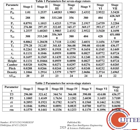
[image:4.595.306.547.71.340.2]Number of blades for rotor row are considered as prime number and for stator are even numbers. So, number of blades for rotor row is 37 and 32 for stator. Table 1 and Table 2 outlines the fundamental parameters of rotor and stator for seven stages.
Table 1 Parameters for seven-stage rotors Paramete
rs Stage I Stage II
Stage III
Stage
IV Stage V
Stage VI
Stage VII P01 1.01 1.2537 1.60203 1.9803 2.4332 2.9522 3.5420
T01 288 308 333.248 356 380 404
428.369 0 P1 0.8791 1.1015 1.4215 1.7710 2.1917 2.6759 3.2284 T1 276.80 297.19 322.05 345.17 369.17 393.17 417.17 P03 1.2537 1.60203 1.9803 2.4332 2.9522 3.5420 4.1698
T03 308 333.248
356.369
0 380 404 428
451.088 0 P2 0.8862 1.28438 1.7118 2.1282 2.6031 3.1456 3.7189 T2 279.28 312.85 341.83 366.08 390.08 414.08 436.57 rt 0.2261 0.2093 0.1918 0.1779 0.1654 0.1545 0.1449 rr 0.1131 0.1046 0.0959 0.0890 0.0827 0.0772 0.0724 rm 0.1697 0.1569 0.1439 0.1334 0.1240 0.1159 0.1086 Height 0.1131 0.10466 0.0959 0.0890 0.0827 0.0772 0.0724 Camber 0.0320 0.0296 0.0271 0.0297 0.0276 0.0257 0.0205 Pitch 0.0288 0.0266 0.0244 0.0267 0.0248 0.0232 0.0185 Density 1.1066 1.2914 1.5379 1.7877 2.0686 2.3714 2.6965
ΔTOS 20 25 23 24 24 24 22
Table 2 Parameters for seven-stage stators Parameter
s Stage I Stage II Stage III Stage IV Stage V Stage VI
Stage VII
T3 296.80 321.62 344.74 366.08 390.08 414.08 436.57
P3 1.1005 1.4149 1.7634 2.1282 2.6030 3.1455 3.7189
rt 0.2093 0.1921 0.1782 0.1671 0.1560 0.1462 0.1381
rr 0.1046 0.0961 0.0891 0.0835 0.0780 0.0731 0.0690
[image:4.595.93.548.413.834.2]International Journal of Innovative Technology and Exploring Engineering (IJITEE) ISSN: 2278-3075, Volume-9 Issue-2, December 2019
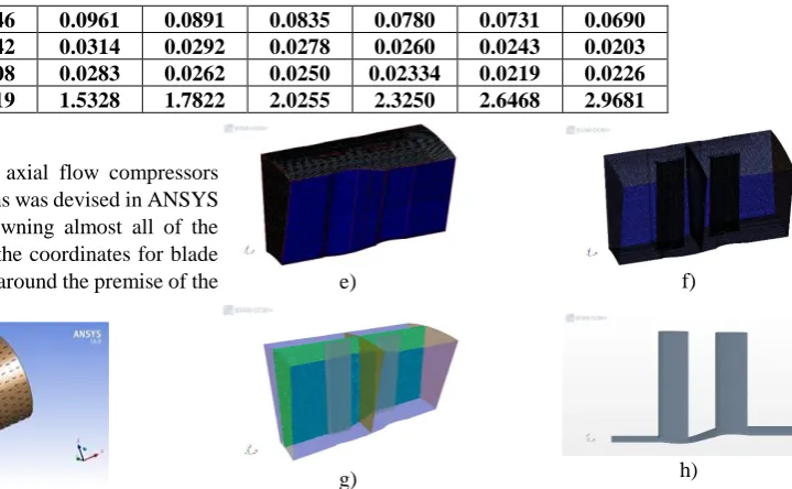
Height 0.1046 0.0961 0.0891 0.0835 0.0780 0.0731 0.0690 Camber 0.0342 0.0314 0.0292 0.0278 0.0260 0.0243 0.0203 Pitch 0.0308 0.0283 0.0262 0.0250 0.02334 0.0219 0.0226 Density 1.2919 1.5328 1.7822 2.0255 2.3250 2.6468 2.9681 D. Creating 3-D Model
The model for the seven-stage axial flow compressors based on thermodynamic calculations was devised in ANSYS Workbench DM 16. Forward to owning almost all of the essential parameters at each stage, the coordinates for blade profile have been calculated on and around the premise of the calibrated blade base profile [11].
a)
b)
[image:5.595.191.551.48.270.2]c)
Figure 1a) Compressor CAD Model b) Seven Stages of axial compressor c) Model imported to STAR CCM +
V. CFDMETHODOLOGY
A. Generating volume mesh
The polyhedral volume mesh is engendered using a base size of 30 mm and prism layer mesher is used to understand the flow parameters. To capture the geometry at the root of both blades the contact prevention of 0.05 mm was used. For the time saving purpose the periodic approach was followed. The volume mesh count for Stage 01 was 1680128.
a) b)
c) d)
e) f)
[image:5.595.64.561.52.424.2]g) h)
Figure 2a) Stage 01 b) Parts of Stage 01 c) Remesher d) Remesher for rotor and stator e) Volume mesh for Stage 01 f)
Volume mesh for rotor and stator g) 3 D view of Meshing h) Geometry captured for rotor and stator blades.
B. Defining Physics Continua
The steady-state simulations were performed in Simcenter STAR CCM+ with the multiple reference frame (MRF) approach to include the effects of both the rotating and stationary components. With the high-speed flows in the rotor, the air was modeled as ideal-gas to account for the compressibility under these conditions. K-omega turbulence model was applied for these simulations. The simulations were conducted in stage by stage approach. For the compressor stage 1, the flow inlet and exit were modeled using stagnation inlet and pressure outlet boundary condition respectively. The pressure obtained at the rotor outlet on stage 1 was applied inlet condition for stage 2 stator.
C. CFD Simulation results
The compressor was designed based on the thermodynamic co-relations and velocity triangle calculations. The primary objective of the project work was to verify that the compressor design from such design approach would perform as per the design variables like mass flow rate, compressor stage outlet pressure. In the following table, the stage outlet pressure comparisons between the analytical calculations and the CFD simulation data had been presented. The difference between these was minimal (14-20%) hence it was concluded that the design approach that was adopted for the compressor was valid.
Table 3 Comparison between analytical and CFD data Parameters\
Methods Analytical CFD Difference
Rotor outlet pressure
(p03)
1.2537 bar 1.4630 bar 16.7%
[image:5.595.95.244.197.453.2] [image:5.595.35.556.604.818.2]VI. CONCLUSION
A multi-stage axial compressor in the Turbojet engine with an application for propulsion is designed based on thermodynamic calculations. The calculations are carried out employing the principles of thermodynamics and aerodynamics along the mean streamline based on the technique of a velocity triangle in the lack of inlet guide vanes (IGVs). The coordinates for the blade profile have been calculated on and around the premise of the calibrated blade base profile. The model for the compressor was devised in ANSYS Workbench DM 16. Seemingly, the use of CFD is an extremely reliable method for supervising the design analysis of axial flow compressors. Multi-stage CFD techniques are worth applying to capture practical physics and consider the 3-D blading method in the multi-stage sense and hence the steady-state simulations were performed in Simcenter STAR CCM+ with the multiple reference frame (MRF) approach to include the effects of both the rotational and stationary components. The analytical and CFD values were compared and it was observed that the difference between these was 16.7%. Hence, it can be concluded that the approach that has been followed for the design and performance evaluation was valid.
REFERENCES
1.Chigbo A. Mgbemene, ―The Design and Fabrication of Low Speed Axial- Flow Compressor Blades by Joukowski Transformation of a Circle‖,
International Journal of Engineering Research & Technology (IJERT),
Vol. 1(8), Oct. 2012, pp. 1-17.
2.Ujjawal, A. J., & Joshi, S. I., ―Design and Analysis of Stator, Rotor and Blades of the Axial Flow Compressor”. International Journal of
Engineering Development and Research, IJEDR1301005, 2013, pp. 24-29.
3.Alm-Eldien, Atef & Abdel Gawad, Ahmed & Hafaz, Gamal & Kreim, Mohamed., Design and Optimization of a Multi-Stage Axial-Flow Compressor, Proc. Of ICFD11: Eleventh International Conference of Fluid Dynamics, Alexandria, Egypt, December 19-21, Dec. 2013, pp. 1-20.
4. Zhang, J., Zhou, Z., Cao, H., & Li, Q., ―Aerodynamic design of a multi-stage industrial axial compressor‖. Advances in Engineering Software, 116, 2018, pp. 9-22.
5. Ning, T., Gu, C. W., Ni, W. D., Li, X. T., & Liu, T. Q., ―Aerodynamic analysis and three-dimensional redesign of a multi-stage axial flow compressor‖. Energies, 9(4), 2016, pp. 296.
6. Pakle, S., & Jiang, K., ―Design of a high-performance centrifugal compressor with new surge margin improvement technique for high speed turbomachinery‖. Propulsion and Power Research, 7(1), 2018, pp. 19-29.
7. Harvey, N. W., ―Some effects of non-axisymmetric end wall profiling on axial flow compressor aerodynamics: Part I—Linear cascade investigation‖. ASME turbo expo 2008: Power for land, sea, and air. American Society of Mechanical Engineers Digital Collection, Jan. 2008, pp. 543-555.
8. Harvey, N. W., & Offord, T. P., ―Some effects of non-axisymmetric end wall profiling on axial flow compressor aerodynamics: Part II—Multi-stage HPC CFD study‖. ASME Turbo Expo 2008: Power for Land, Sea, and Air. American Society of Mechanical Engineers Digital Collection, Jan. 2008, pp. 557-569.
9. Zhang, C., Hu, J., Li, J., & Wang, Z., ―Three-dimensional compressor blading design improvements in low-speed model testing‖. Aerospace Science and Technology, 63,2017, pp. 179-190.
10. Lu, H., Li, Q., & Pan, T., ―Optimization of cantilevered stators in an industrial multistage compressor to improve efficiency‖. Energy, 106, 2016, pp. 590-601.
11. Saravanamuttoo, H. I., Rogers, G. F. C., & Cohen, H, ―AXIAL FLOW COMPRESSORS‖, Gas turbine theory. (5th ed.) India: Pearson Education, 2001, pp. 181-262.
12. Hu, J., Li, Q., Pan, T., & Gong, Y., ―Numerical investigations on stator hub-initiated stall in a single-stage transonic axial compressor‖.
Aerospace Science and Technology, 80, 2018, pp. 144-155.
13. Chang, H., Zhu, F., Jin, D., & Gui, X., ―Effect of blade sweep on inlet flow in axial compressor cascades‖. Chinese Journal of Aeronautics, 28(1),2015, pp. 103-111.
AUTHORSPROFILE
Cheke Kuldeep Damodhar completed his graduation in Mechanical Engineering from Sinhgad Institute of Technology, Lonavala, Pune, Maharashtra with distinction and completed his project under the guidance of Dr. A. G. Kamble. He pursues his Master's degree in Heat Power from Maharashtra Institute of Technology Academy of Engineering, Alandi, Pune. His areas of interest are computational fluid dynamics (CFD), turbomachinery, optimization and have one research publication on the use of multi-attribute decision-making methods for the ethanol blending selection with petrol. Also, he is pursing diploma in CFD course using STAR CCM+ software in which he has completed the project on Radiator, Catalytic Convertor and Ahmed body.