Abstract: The control aspects of pulp level in a flotation column is a difficult task as the complex structure of cell configuration and the higher interaction as number of cells used in the configuration increases. This paper analyses about different control approaches for level control in flotation columns. The conventional method of controller design and other algorithmic and heuristic control are reviewed.
Keywords: Flotation, Deinking
I.INTRODUCTION
Paper is one of the most important inventions of mankind. Paper is intertwined in our day today life and its need is
inevitable. Paper are used in the form of news paper, text books, note books, novels, documents, journals in our personal lives, houses, schools, work places and in public life. Though many people moved to digital version to keep paper usage to minimum but still most of the population is obsessed with paper and paper based products in their day today life. Paper is the product from fibers of vegetable origin, mostly of wood. In order to protect environment and to decrease the cutting of trees, which are used as the raw materials for paper production, the recycling of the used papers for obtaining the fibers for the production of the recycled papers is necessary.
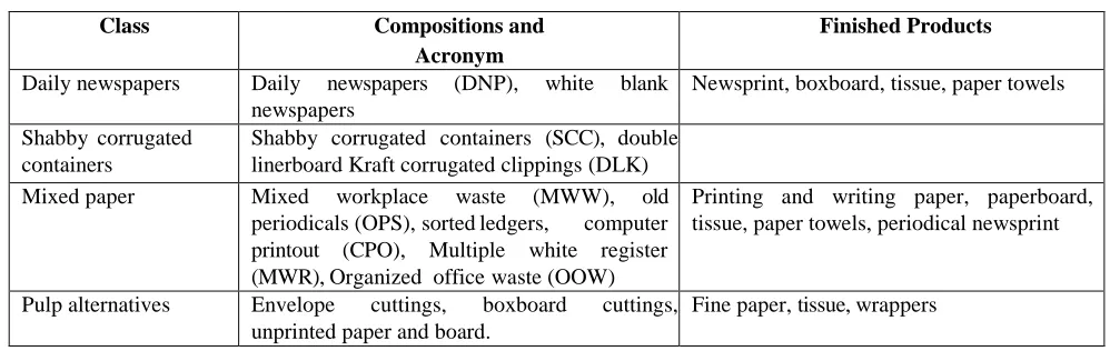
Table. 1Waste Papers Classification and finished products
Class Compositions and
Acronym
Finished Products
Daily newspapers Daily newspapers (DNP), white blank
newspapers
Newsprint, boxboard, tissue, paper towels
Shabby corrugated containers
Shabby corrugated containers (SCC), double linerboard Kraft corrugated clippings (DLK)
Mixed paper Mixed workplace waste (MWW), old
periodicals (OPS), sorted ledgers, computer printout (CPO), Multiple white register (MWR), Organized office waste (OOW)
Printing and writing paper, paperboard, tissue, paper towels, periodical newsprint
Pulp alternatives Envelope cuttings, boxboard cuttings, unprinted paper and board.
Fine paper, tissue, wrappers
The field of recycling paper attracting more attention nowadays to save natural resource that is trees. This field rapidly develops the recycling process for reprocessing of secondary fibers in papers called as deinking. This recycling process is improving day by day and becoming more and more efficient and recycled papers are becoming popular and its usage is increasing rapidly. The quality of paper called the virgin paper is made available with that of the use of the secondary fibers. The process is more eco-friendly than the virgin-paper-making process.
The process of removing inks and other non-fibrous contaminants is called De-inking. Units like washing, floatation, cleaning and screening are required to separate inks from fibers. The units operation and selection will change based on the waste paper category and requirements of the completed de-inked pulp. The waste paper comprises of the categories comprising of the mixed paper, old daily newspapers, old shabby corrugated containers, pulp alternatives.
Revised Manuscript Received on March 08, 2019.
T.Maris Murugan, Associate Professor, Department of Electronics &Instrumentation Engineering, Erode Sengunthar Engineering College, Perundurai, Erode, India
R.Kirubashankar, Associate Professor, Department of Mechatronics, Kongu Engineering College, Perundurai, Erode, India
Table 1 summarizes wastepaper classification and the finalized products that can be produced from different kinds of waste papers.
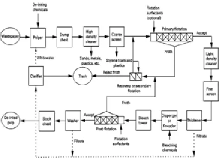
II. PRODUCTION LINE FOR DEINKING PLANT The process that is used to produce deinked pulp from recovered paper, which is usually a mixture of old newspapers (DNP) and old periodicals (OPS) is popularly known as De- inking in the field of paper recycling. The fibre pulp obtained by this recycling method is usually a blend of fibres and other non-paper elements like, binders, pigments, additives and fillers. To produce a quality paper this blended product has to undergo various process. A deinking line has various progressive operations unit that are linked together in discrete ways. To achieve higher quality of pulp the process in each unit will differ from mill to mill, there are mills that have a second or even a third stages in order to achieve a higher quality of pulp. A simplified version of single stage deinking process line for yeilding deinked pulp is presented in Fig 1.
A Study of Flotation Control
[image:1.596.48.547.296.454.2]The Deinked recycling of pulp production starts with repulping of the retrieved paper, where individual fibers and particles are treated with the help of warm water and chemicals. The intention is to separate printing ink from fibers. At the end of this process, the pulp goes through a screening unit, normally with 6–20 mm holes [2] to break down large non-paper elements such as plastic foils, CD’s, twines, textiles, wet strength paper, bottles, wires, etc. from the pulp. It is very important to remove solid contaminants at very initial stage as much as possible so that they do not hold up the forth coming stages or break down into relatively small particles. Depending on the quality of the recycled paper, around 1% of the raw material added into the process is rejected in pulping [3]. To remove the debris and other solid wastes, the pulp suspension is run through different screens based on the dimension of particle, nature and deformability of the impurities. The large waste consist of staples, sand, flakes, and grits are eliminated through the process of coarse screening. The next process is to remove macro stikies and the dirt specks and this is done through fine screening. It is almost impossible to complete the screening of the pulp without notable fiber loss so the rejected pulp from first state undergo another series of screening in the second and third and even fourth stage At the end of all these screening the fiber loss is usually between 1% -2% [1]. The purpose of screening is to maximise the cleaning quality and minimize fiber loss. i.e. the screens can be either in the shape of discs (holes 2.0–3.0 mm) or cylinders (holes 0.8–1.5 mm or slots 0.08–0.4 mm), and either highly pressurized or at atmospheric pressure [2]. Bigger holes are used at the starting of the process line, while holes become narrow in the middle and at the end. Centrifugal cleaning with hydrocyclones is an essential separation process that helps to improve the quality and makes it easy for other methods such as screening. Depending on the operation mode, elements with high or low density compared with the water are parted out by cleaning. This mostly consist of plastic foam and other plastic things, or sand, cut-glass, shives and piece of metal. About 0.5%-1.5% [3] is the loss in the yield attributable to the centrifugal cleaning.
Fig. 1 Flow diagram of Deinking Plant
A very important process called “selective flotation” is a used for removing ink and micro stickies in tissue paper production. To achieve this air bubbles are fed into the pulp suspension at about 1%–1.2% consistency, as a result
hydrophobic particles will be attached to them and starts floating to the surface, where they form foam that can be easily eliminated. These foam contain binders, fillers, stickies and dyes. On account of mechanical entrainment [4] some fibers can end up in the foam while the Hydrophilic fibers remain in the pulp suspension. There are many different flotation stages that are carried out for the efficient removal of contaminants (preflotation and post-flotation stages). A largest waste of about 8-16% of raw material is produced in DIP mill is mainly due to the rejects of both floatation stages [1].
The consistency is increased as it requires in the subsequent stages and the water loops are separated through dewatering and thickening of the pulp. Dewatering is classically carried out with a combination of a disc filter and a screw press, while dissolved air flotation (DAF) is used for washing condensing filtrates. The slurry consists of colloidal material, ink, fibers and fillers. The loss of yield in this process is about 1%–5% [1]. To accomplish superior pulp quality, it may be dispersed and bleached. Dispersion breaks down the enduring impurities to a size at which they usually no longer interfere. To improve optical characteristics of the fibre, one more bleaching stage may be supplemented in the deinking line at its end.
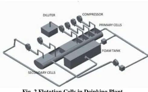
III. FLOTATION DE-INKING SYSTEM The pulp is drenched in a dump chest for swelling the fibers to improve the removal of ink. The stock is later aerated at 0.7 - 1.5% consistency in a series of flotation cells. In Primary flotation six to ten flotation cells in series are essential for increase the efficiency of ink removal. The fibre recovery is increased and fibre loss is decreased by cleaning the froth collected from primary flotation in a secondary stage.
The grouping of flotation and cleaning stages aided by the technical improvements are utilized to remove the inks from the more complex wastepaper. A disperger or kneader is added between two standard flotation stages in the post flotation. The additional detachment and the size miniaturization of the ink and other non-fibrous particles are amply aided by the dispersion or the kneading stage. The overall flotation performance is improved consequently.
Fig. 2 Flotation Cells in Deinking Plant
The flotation chamber as in Fig.2 consists of primary and secondary cell. The low consistency pulp from the Diluter is well mixed with the surfactants and fed to the first cell of the primary flotation chamber. The primary cell usually consists of five cells, which are connected in an interactive fashion. The compressed air is passed through each cell. The ink particles from the fiber are attached to the air bubbles due to its hydrophobic nature and move to the top of the cell as foam. Froth overflows from the cell are collected in a tank. The deinked pulp will move to the Thickener process. The foam and the Pulp overflowed from the primary cell in the foam tank are sent to the secondary cell which usually comprises of two cells.
IV. CONTROL STRATEGY
Controlling of pulp level in flotation cells is a highly difficult task due to heavier interactions between the process variables. A control action may be transmitted in previous and as well as in the next stage with or without amplification if it is applied at any part of the flotation control circuit. Flotation cells are generally controlled by isolated PI-controllers. For a single flotation unit, PI controller will be good but in strong interacted flotation control circuits the performance of the controller will not meet out the requirements. A lot of research work has been carried for the flotation circuits Jeamsea- and their better control techniques for the past few years. Flotation process also applied in the metallurgical field for the separation of pulp. Here it is discussed the various control strategy applied in flotation control using conventional control and various algorithms.
The simplest method is the automatic control of froth depth with the flow rate of tailing, and the manual control of wash flowrates. Apart from being economical and simple, this method has no interaction with other objectives. Another commonly used method is control of froth depth with the wash water flow rate, and the relative bias with the flowrate of tailing. The relative bias is the difference between the flowrates of tailing and feed. Reposition of the froth depth is slower than in the previous scheme and modifies the bias rate. The response to the variation in the flowrate of the feed is high in bias control via the flowrate of tailing. In practice [12] both arrangements have shown that due to the absence of synchronization, the gain of the two controllers have been lost. Occasionally an additional controller is implemented for controlling the holdup volume
of gas with the flowrate of gas. The overall performance will be improved by detuning more than one controller in three autonomously tuned control loops generally with strong interactions between them. The presence of non-linear behavior leads to unsatisfactory performance and stability problem may arise if the operating region is changed even though the controller is very well tuned. This is another reason for detuning controllers, giving lethargic reactions. Since the process is highly complex, handling them with the conventional algorithms like PID controllers will not yield satisfactory response and the control will become worse if measurement errors are large.
In recent years, several different tactics are came into existence to control the flotation columns. Two 15 meter high and 2 square meter flotation column in Nerco Con Mine in Yellowknife, Canada [13] implemented with expert control is used to separate the gold bearing arsenopyrite from pyrite in a refractory ore and for controlling of two 2.5 m diameter by
14.3 m high flotation columns for lead cleaning at the Doe Run Compnay’s Viburnum Operation in Missouri, U.S.A.[13]. In both flotation column, three differential pressure devices are used to estimate the bulk densities in each zone. The flowrate of wash water and gas are manipulated to maintain the density in each zone. The conventional controller is used to control the forth depth by adjusting the flowrate of tailing.
A 2.7 meter diameter and 13.5 meter high flotation column in Toyoha mines in Hokkaido, Japan [14] is implemented with fuzzy control to evaluate the Zinc. The conventional control method controls the height of the froth with the flowrate of the tailing. The set point of flowrate of gas has been changed by fuzzy algorithm to maintain the concentrate grade, where the concentrate grade and tailing grade are measured online. The flowrate of tailing is used to alter the logical decision which includes the pH change and amount of carbon when flowrate of gas is not able to drive the concentrate grade to its set point.
A finest control algorithm through the application of maximum principle was developed for single flotation cell by Niemi in 1974 and Koivo and Cojacariu in 1977 [6] [7]. The flotation control with the state feedback control and a kalman filter was implemented by Andersen in 1979 and Zargiza and Herbst in 1987 [8] [10]. Hammounde and Smith in 1981 develop a minimum-variance controller with a linear model
[9] and Sherlund & Medvedev in 2000 recommended a novel advanced control method for the flotation column [11]. The techniques to control the flotation cell levels with minimum- variance controller,[18], the state feedback controller with kalman filter[19], a conventional PI controller [20], and a feed-forward control with a conventional isolated PI controller
[21] are only effective for the control of isolated cells and are not suitable for series of cells.
In Boliden’s concentrator in Aitik, the controlling of level in flotation cell was developed with a multivariable decoupling controller with compensator [22]. A simulation of flotation control with a decoupling controller eliminates the adverse effects of control loops [23]. Even though the control tactics in the simulation of level controllers were good for the linear decoupling, it should be noted that there exist strong astonishing nonlinearities and parameter uncertainties in practical flotation circuits.
The linear adaptive decoupling controller assures the stability of the system but does not consider the effects of nonlinearities in the output. The non-linear adaptive decoupling controller can reduce the effects of nonlinearity at the cost of stability of the system. To tradeoff between this ANFIS based adaptive decoupling controller which has linear adaptive decoupling controller and a switching mechanism based ANFIS nonlinear adaptive decoupling controller.
In general, the conventional three mode controller or model based controller like MPC, IMC, DMC etc., can be used to optimize the process in a narrow region of operation with the compromise of robustness in outside the region but heuristic control based on logical rules such as fuzzy control and other expert system avoids the process parameter to drive outside the operating region but the efficiency of managing the dynamic progression of control variable is less.
The Coefficient Diagram Method in a strong pH neutralization process gives a convenient and flexible design with a stability and robustness conditions reveals great performance against disturbance rejection in [26]. In [27], for nonlinear conical tank liquid level control system, the author concluded that the CDM – PI control scheme works well for nonlinear interacting system. The CDM controller achieved a steady arrangement on the non-linear heat exchanger process with changing operating levels in [28]. In [29], 2DOF controller using CDM technique was applied to three tank interacting process and achieved a better performance in practical environment. Multi loop CDM – PI controller for three tank process clearly reveals a good servo control without any residual error with a little settling time [30].
V. CONCLUSION
An alternative method has to be implemented in flotation column control to overcome the difficulty in using the conventional PID, Model based control or the Heuristic control. The Coefficient Diagram Method (CDM) is an algebraic methodology which combines conventional and recent control design. The CDM design well balances the stability and robustness of the system. An effective controller for flotation column control with finest bandwidth and no residual error can be obtained for particular settling time because the CDM strategy is governed by the stability index and equivalent time constant.
ACKNOWLEDGMENT
We would also like to acknowledge Mr.Shanmugavadivel, Manager, Mechanical, De-inking plant, TNPL Karur for sharing his rich expertise in the field. We would like to thank Mr.Murali ,Assistant Manager, Instrumentation, De-inking plant, TNPL Karur for his immense contribution of technical knowledge towards this paper.
REFERENCES
1. Hamm U (2010) Final disposal of waste from recycled fibre-based
papermaking and of non-recycled paper products. In: Höke U &Schabel S (eds) Recycled fibre and deinking. 2nd edition, Helsinki, Finnish Paper Engineers’ Association: 562–646.
2. Schabel S &Holik H (2010) Unit operations and equipment in recycled
fibre processing. In: Höke U &Schabel S (eds) Recycled fibre and deinking. 2nd edition, Helsinki, Paper Engineers’Association: 122–278
3. Pöyry (1995) Jaakko Pöyry Consulting AB report: Deinking
developments. Tummavuorenkirjapaino Oy, Finland.
4. Ajersch M (1997) Mechanisms of pulp loss in flotation deinking. Open
Access Dissertations and Theses. Paper 3377. Cited 2012/08/08.URI: http://digitalcommons.mcmaster.ca/opendissertations/3377
5. Jeamsea-Jounela, S.-L., Laurila, H., Karesvuori, J., Timperi, J., 2001. Evaluation of the future automation trends in control and fault diagnostics––a case study in flotation plant. In: 10th IFAC Symposium on Automation in Mining, Mineral and Metal Processing.
6. Niemi, A., Maijanen, J., Nihtil€a, M., 1974. Singular optimal feed
forward control of flotation. In: IFAC/IFORS Symposium on Optimization Methods––Applied Aspects. Varna, Bulgaria, pp. 277– 283.
7. Koivo, H., Cojocariu, R., 1977. An optimal control for a flotation circuit. Automatica 13 (1), 37–45.
8. Andersen, R., Gronli, B., Olsen, T., Kaggernd, I., Ramslo, K., Sandvik,
K., 1979. An optimal control system of the rougher flotation at the FolldalVerk concentrator, Norway. In: Proceedings of the 13th International Mineral Processing Congress. New York, USA, pp. 1517– 1540.
9. Hammoude, A., Smith, H., 1981. Experiments with self-tuning control
of flotation. In: Proceedings of the 3rd IFAC Symposium on Automation in Mining, Mineral and Metal Processing. Oxford, UK, pp. 213–218.
10. Zargiza, R., Herbst, J.A., 1987. A model based feed forward control scheme for flotation plants. In: 116th AIME annual meeting. Denver, CO, USA, pp. 23–27.
11. Stenlund, B., Medvedev, A., 2000. Level control of cascade coupled flotation tanks. Future trends in automation in mineral and metal processing. In: J€ams€a-Jounela, S.-L., Vapaavuori, E. (Eds.), IFAC Workshop 2000, Helsinki, Finland, pp. 194–199.
12. Feely C.D., Landoit C.A., Misczack J. and W.M.Steeburgh, Column
13. Kosics G.A., Dobby G.S., and P.D. Young, ColumnEx: A Powerful and Affordable Control System for Column Flotation, Proceeding International Conference on Column Flotation, Sudbury, Canada, 359 (1991).
14. Hirajima T., Takamori T., Tsunekawa M., Mastubara T., Oshima K.,
Sawaki K. and S. Kubo, The Application of Fuzzy Logic to Control Concentrate Grade in Column Flotation at Toyoha Mines, Proceeding International Conference on Column Flotation, Sudbury, Canada, 375 (1991).
15. Pu M., Gupta Y.P., and A.M. Al Taweel, Model Predictive Control of
Flotation Columns, Proceeding International Conference on Column Flotation, Sudbury, Canada, 467 (1991).
16. Cutler C.R., and B.L. Ramarker, Dynamic Matrix Control, A Computer
Control Algorithm, AIChE 86th Meeting, Paper 51b (1979).
17. Manabe.S., (1998), The Coefficient Diagram Method, 14th IFAC
symposium on Automatic control in Aerospace, May 24-28.
18. Hammoude, A. and H. Smith, 1981. Experiments with selftuning
control of flotation, Proc. 3rd IFAC Symp. Automation In Mining, Mineral And Metal Processing. Oxford, UK, pp. 213–218
19. Zargiza, R. and J. A. Herbst, 1988. Model based feedforward control scheme for flotation plants, SME Annual Meeting, Denver, Colorado, pp. 177–185
20. Carr, D., A. Dixon, and O. Tiili, 2009. Optimizing large flotation cell performance through advanced instrumentation and control, Proc. 10th Mill Operators Conf., Adelaide, Australia, pp. 299–304
21. Wills, B. A. and T. Napier-Munn, 2006. Wills’ Mineral Processing
Technology, 7th Edn. Oxford, UK: Butterworth Heinemann, pp. 267– 344
22. Stenlund, B. and A. Medvedev, 2002. Level control of cascade coupled
flotation tanks, Control Eng. Prac.,Vol. 10, No. 4, pp. 443–448.
23. Kämpjärvi, P. and S.-L. Jämsä-Jounela, 2003.“Level control strategies
for flotation cells,” Minerals Eng., Vol. 16, pp. 1061– 1068
24. Moilanen, J. and A. Remes, 2008. Control of the flotation process,” In:
R., Kuyvenhoven, C., Gomez, and A. Casali, (Eds), Procemin 2008, V International Mineral Processing Seminar, Santiago, Chile, pp. 305– 313
25. Haibo Li, Tianyou Chai, Jun Fu, and Hong Wang, 2013, Adaptive
Decoupling Control of Pulp Levels in Flotation Cells, Asian Journal of Control. Vol. 15 No. 5 pp 1434 – 1447.
26. B.Meenakshipriya,K.Saravanan, K.Krishnamoorthy &P.Kanthabhabha,
2015. pH control of industrial effluent using CDM based PI controllers, Indian Journal of Chemical Technology, Vol. 22, pp 141 – 147
27. P.K.Bhabha & S.Somasundaram, 2009. Real time implementation of a
new CDM – PI control scheme in a conical tank liquid level maintaining system, Modern Applied Science, Vol. 3, No. 5, Page no. 38 – 45
28. Erkan IMAL, 2009. CDM based controller design for nonlinear heat
exchanger process, Turk J Elec Eng& Comp sci, Vol. 17, No. 2, page no. 143 – 161
29. K.Senthil Kumar & Dr.D.AngelineVijula, 2015. Implementation of two
degree of freedom (2DOF) controller using Coefficient diagram method techniques for Three tank interacting system, International Journal of Engineering and Technology, Vol. 2, Issue 9, page no. 90 – 96