UNIVERSITI TEKNIKAL MALAYSIA MELAKA
BATTERY FLAT PREVENTER DEVICE DESIGN FOR CAR
BASED ON BANG-BANG CONTROLLER OF CURRENT
LIMITER
This report is submitted in accordance with the requirement of the Universiti Teknikal Malaysia Melaka (UTeM) for the Bachelor of Electrical Engineering
Technology (Industrial Automation and Robotics) with Honours.
by
HIZRIAN BIN AN EFENDI B071310247
910519-07-5475
UNIVERSITI TEKNIKAL MALAYSIA MELAKA
BORANG PENGESAHAN STATUS LAPORAN PROJEK SARJANA MUDA
TAJUK: Battery Flat Preventer Device Design For Car Based On Bang-Bang Controller of Current Limiter
SESI PENGAJIAN: 2016/17 Semester 1
Saya HIZRIAN BIN AN EFENDI
mengaku membenarkan Laporan PSM ini disimpan di Perpustakaan Universiti Teknikal Malaysia Melaka (UTeM) dengan syarat-syarat kegunaan seperti berikut:
1. Laporan PSM adalah hak milik Universiti Teknikal Malaysia Melaka dan penulis. 2. Perpustakaan Universiti Teknikal Malaysia Melaka dibenarkan membuat salinan
untuk tujuan pengajian sahaja dengan izin penulis.
3. Perpustakaan dibenarkan membuat salinan laporan PSM ini sebagai bahan pertukaran antara institusi pengajian tinggi.
4. **Sila tandakan ( )
SULIT
TERHAD
√ TIDAK TERHAD
(Mengandungi maklumat yang berdarjah keselamatan atau kepentingan Malaysia sebagaimana yang termaktub dalam AKTA RAHSIA RASMI 1972)
(Mengandungi maklumat TERHAD yang telah ditentukan oleh organisasi/badan di mana penyelidikan dijalankan)
Alamat Tetap:
182 Jalan Masjid,Jelutong
11600 Georgetown
Pulau Pinang
Tarikh: ________________________
Disahkan oleh:
Cop Rasmi:
Tarikh: _______________________
i
DECLARATION
I hereby, declared this report entitled “Battery Flat Preventer Device Design For Car Based On Bang-Bang Controller Of Current Limiter” is the results of my own
research except as cited in references.
Signature : ……….
Author’s Name : HIZRIAN BIN AN EFENDI
ii
APPROVAL
This report is submitted to the Faculty of Engineering Technology of UTeM as a partial fulfillment of the requirements for the degree of Bachelor of Electrical Engineering Technology (Industrial Automation and Robotics) with Honours. The member of the supervisory is as follow:
iii
ABSTRAK
Projek ini adalah mengenai pembangunan peranti yang mengehadkan penggunaan
arus dari bateri kereta jika terdapat alat elektrik berkuasa sederhana dan tinggi
(MHPEP) masih lagi berfungsi apabila pengguna/pemandu meninggalkan kereta.
Situasi ini sering berlaku apabila pemandu kereta atau penumpang terlupa untuk
mematikan MHPEP apabila meninggalkan kereta. Penggunaan MHPEP yang
terlalu lama semasa keadaan enjin mati boleh menyebabkan bateri kehabisan kuasa
seterusnya menyebabkan enjin tidak dapat dihidupkan. Peranti ini dibangunkan
untuk mengatasi masalah ini dan berkebolehan untuk mengehad penggunaan bateri
jika terdapat MHPEP yang masih berfungsi jika tiada pemandu atau penumpang di
dalam kereta. Komponen utama peranti yang dibangunkan ini terdiri daripada
pengawal mikro Arduino UNO, penderia arus, geganti dan pemban amaran.
Pengawal buka-tutup digunakan untuk mengawal pengehad arus. Pada akhir projek
ini, peranti yang dibangunkan boleh mengehadkan arus bateri apabila MHPEP
masih lagi hidup semasa keadaan enjin mati seterusnya mengelakkan bateri
iv
ABSTRACT
v
DEDICATION
Special dedication to
vi
ACKNOWLEDGEMENT
I would like to take this opportunity to express my deepest gratitude to my project supervisor, Dr Mohd Badril Bin Nor Shah who has persistently and determinedly assisted me along the progress of the project. It would have been difficult to complete this first half of the project without enthusiastic support, insight and advice given by him.
vii
TABLE OF CONTENT
Abstrak iii
Abstract iv
Dedication v
Acknowledgement vi
Table of Content vii
List of Tables ix
List of Figures x
List Abbreviations, Symbols and Nomenclatures xii
CHAPTER 1: INTRODUCTION 1
1.0 Project Background 1
1.1 Problem Statement 2
1.2 Objective 2
1.3 Scope of Work 3
1.4 Report Outline 4
CHAPTER 2: LITERATURE REVIEW 7
2.1 Introduction 5
2.1 Battery Draining Prevention Device 5
2.2 Solid State Relay 7
2.3 Hall-Effect Current Sensor 8
2.4 The Arduino Microcontroller 8
2.5 Related Previous Work 11
2.5.1 Current Limiter 11
2.5.2 Using PID as The Control Scheme for The System 13
2.5.3 Bang-Bang Controller 17
viii
CHAPTER 3: METHODOLOGY 20
3.0 Introduction 17
3.1 Project Design 17
3.1.1 The Arduino UNO Microcontroller 23
3.1.2 The Solid-State Relay (SSR) 24
3.1.3 Buzzer 25
3.1.4 Hall Effect Current Sensor 25
3.1.5 Relay Module Single Channel 26
3.2 Controller Design 27
3.3 Hardware Development 29
3.4 Programming Development 31
CHAPTER 4: RESULTS AND DISCUSSION 33
4.0 Introduction 33
4.1 Data of Drawn Current from Cars When Engine-Off Condition 33
4.2 Circuit Simulation 34
4.3 Experimental Results 34
CHAPTER 5: CONCLUSION 39
5.0 Introduction 39
4.1 Summary of Research 39
4.2 Achievement of Objective 39
4.3 Suggestion of Future Work 40
REFERENCES 41
APPENDICES 42
ix
LIST OF TABLES
2.1 The technical specification of Arduino Uno 10
2.2 The power pins of Arduino Uno board 10
2.3 The equation of controlled system with compensation 17
4.1 The drawn current car during engine-off condition 27 4.2 Data of battery current over time for case battery current >
current limit
35
4.3 Data of battery current vs time for case battery current < current limit
x
LIST OF FIGURES
2.1 Battery draining prevention device 7
2.2 The Arduino UNO board 9
2.3 Circuit for a power supply current limiter using 1 diodes and 3 resistors
11
2.4 Complicated circuit which more low voltage drop 12
2.5 Circuit current limiter with using LM317 12
2.6 The block diagram of the process under PID control 13
2.7 The simplified block diagram 14
2.8 The proportional characteristic 14
2.9 The transfer function, the algorithm and the gain for proportional control
15
2.10 The transfer function, the algorithm and the gain for integral control
15
2.11 The transfer function and algorithm for derivative control 16
2.12 The estimation of open loop time constant 16
2.13 Example of waveform of Bang-Bang Controller 18
2.13 Example of waveform of Bang-Bang Controller 18
3.1 The flowchart of methodology of this project 21
3.2 The field diagram at the proposed device 22
3.3 The Arduino UNO microcontroller 23
3.4 The solid-state relay (SSR) 24
3.5 The buzzer 25
3.6 Hall effect current sensor 25
3.7 Relay module single channel 26
3.8 The block diagram of bang-bang control of current limiter as battery flat preventer for car
27
xi
LIST OF FIGURES
3.10 Car head lamp represent a MHPEP in this project 30
3.11 Car battery that is used in this project 30
3.12 Flowchart of programming sequence of this project 32
4.1 Connection in Proteus Software 34
xii
LIST OF ABBREVIATIONS, SYMBOLS AND
NOMENCLATURE
A - Ampere
Ah - Ampere hour
AC - Alternating Current CHR - Chien Hrones Reswick
dB - Decibel
DC - Direct Current
GND - Ground
ICSP - In-Circuit Serial Programming LCD - Liquid Crystal Display
LED - Light Emitting Diode
MHPEP - Medium and High Power Electrical Parts
MHz - Megahertz
PID - Proportional-Integral-Derivative PWM - Pulse Width Modulation
SLA - Sealed Lead Acid SSR - Solid State Relay USB - Universal Serial Bus
V - Voltage
VAC - Volts of Alternating Current
1
CHAPTER 1
INTRODUCTION
1.0 Project Background
Battery is among the most important parts in a car. It enables a car to perform crank start to activate the combustion process inside engine chamber. During engine-off condition, a car battery supplies electrical energy to some electric and electronic parts such as radio, alarm system, lamps, power windows, to name a few. The battery is charged by alternator during engine run condition. 12V sealed lead acid (SLA) battery type always used in a car since it can provide high current capacity at low cost.
Current limiter is a device in electrical or electronic circuits of imposing an upper limit on the current that may be delivered to a load for protection propose. Inappropriate high current may cause fire hazard, damage to other components or fast energy depletion. Current limiting operation can be performed either by using analog components or algorithm that is written into microcontroller.
2
1.1 Problem Statement
A modern car commonly equipped with medium and high power electrical parts (MHPEP) such as head lamp, fog lamp, radio and amplifier. The MHPEP consume quite significant amount of electrical current. During engine run condition, MHPEP obtain the electrical power from the alternator, but during engine off condition, the power of MHPEP is supplied by car battery.
Long usage of MHPEP during engine off condition can cause car battery depletion or flat, thus lead to engine start problem. This situation always occurs when car driver or passenger forget to turn off the MHPEP when leaving the car. Besides that, fault current due to short circuit of wiring or electrical equipment can lead to same problem. To prevent such problem, a potential device that capable to give warning can be developed to indicate the MHPEP is still functioning once car driver or passenger leaving their car. The device also capable to limit drawn current from the battery if the MHPEP is still switch on when there is no car driver or passenger in the car.
1.2 Objective
The aims of this project are:
a) To design a circuit that capable to give warning if MHPEP is still switch on when car driver or passenger leaving their car.
b) To design closed loop control current of current limiter circuit to limit the drawn current from car battery that is consumed by MHPEP.
3
1.3 Scope of Work
The scopes of the project are:
a) Circuit design
Microcontroller based circuit will be designed where it will be designed where it will be connected to human detector sensor. Solid-state relay (SSR) will be connected to the circuit as interfacing between car battery to electrical systems.
b) Controller Design
Closed loop control is required to enable adjustable current limiter operation for car battery
c) Simulation
The performance of the designed circuit and controller will be evaluated through simulation.
d) Hardware prototype
4
1.4 Report Outline
This report is organized into 5 chapters and the outline of each chapter is briefly explained as follows.
In Chapter 1 explains the introduction of the project, which includes the background, problem statements, objectives and the work scope of the project.
In Chapter 2, the chapter briefly explains the review of theories, experimental works and some findings that had been done during the past research that is related to the current project.
In Chapter 3, methodology and strategy to achieve the objectives is explained in detail. The working procedure, materials and apparatus are well also covered.
Chapter 4 shows the results and discussion. The results analysis is also included.
Finally, in Chapter 5, the conclusion for this project is presented. The suggestion for future work is also covered in this chapter.
5
CHAPTER 2
Literature Review
2.0 Introduction
In this chapter, all components and all information that related to this project are describe. This chapter review created to get an idea about the specification, project design, conception and any information that related to this project. The flows of the system are based on the reviews made from research on car problem.
2.1 Battery Draining Prevention Device
In the online market for the car, there are device that can prevent battery to flat out that is BlackVue Power Magic Pro ‘Battery Draining Prevention Device’. BlackVue Power Magic Pro have same application with the ‘Battery Prevention for Car’ but this device only work for the dashboard camera and not with all MHPEP in the car. This product is a little control box that ties car's electrical system and gives new devoted outlet to connect to the dashboard camera (out of view underneath the dashboard).
6
The Battery Draining Prevention Device enables the “parking mode", where the dashboard camera can keep watch over car while it is parked. While in parking mode, the dashboard camera draws power from the vehicle battery, however users don't have to worry returning to discover car not able to start because of a drain battery, since it is always monitoring the car battery and will turn off the dashboard camera when the battery level fall underneath a specific (adjustable) limit.
It will automatically cut off the power to dashboard camera when voltage drops below the minimum voltage setting. Moreover, it also acts as a countdown timer where user can set the preferable duration to have the dashboard camera operates when parked. It helps to prevent further draining of battery voltage when vehicle is parked for longer period.
7
Figure 2.1: Battery draining prevention device
2.2 Solid-State Relay (SSR)
A solid-state relay is a control relay with an isolated input and out-put, whose functions are achieved by means of electronic components without the use of moving parts such as those found in electromechanical relays. These solid-state electrical relays are ideal for applications that have many contact closures, since solid state relay switches offer a greatly extended life compared to electromechanical relays.
8
In the case of non-zero voltage crossover relays, the output of the solid-state switch is turned on at the precise voltage occurring at the time. Removal of the input power disables the control circuit, and the solid-state relay switch is turned off when the load current passes through the zero point of its cycle.
Solid-state relays have features which electromechanical relays do not such as: • Long life
• Shock and vibration resistance • Generation of RFI, EMI • No contact bounce • Arc less switching • Acoustic noise
• Zero voltage switching • IC compatibility
• Immunity to humidity, salty environment and dirt
2.3 Hall-Effect Current Sensor
9
2.4 The Arduino Microcontroller
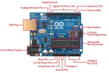
[image:23.595.137.516.213.466.2]The Arduino UNO is a microcontroller board with 14 digital input/output pins (6 of it can use as PWM output), 6 analogue input, USB connection, 16Mhz crystal oscillator, a power jack, a reset button and ICSP header. Figure 2.2 show the Arduino UNO board.
Figure 2.2: The Arduino UNO board
10
[image:24.595.104.533.140.312.2]Technical Specification
Table 2.1: The technical specification of Arduino UNO Features of Arduino Board
Operating Voltage 5V
Input Voltage (recommended) 7-12V
Input Voltage (limits) 6-20V
Digital I/O Pins 14 (6pin for PWM output)
Analog Input Pins 40mA
DC Current for 3.3V Pin 50mA
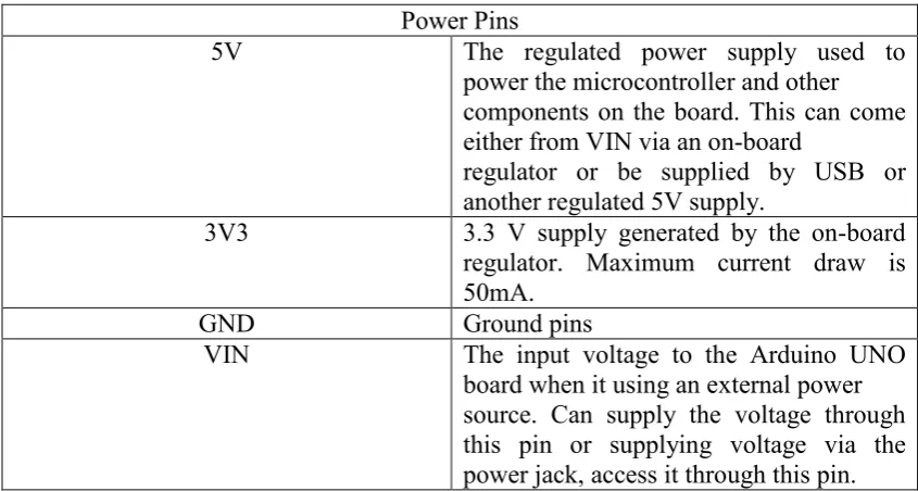
Table 2.2: The power pins of Arduino UNO board Power Pins
5V The regulated power supply used to
power the microcontroller and other components on the board. This can come either from VIN via an on-board
regulator or be supplied by USB or another regulated 5V supply.
3V3 3.3 V supply generated by the on-board regulator. Maximum current draw is 50mA.
GND Ground pins
[image:24.595.107.530.364.590.2]