© 2017 IJSRST | Volume 3 | Issue 7 | Print ISSN: 2395-6011 | Online ISSN: 2395-602X Themed Section: Science and Technology
Improvement of Transient Stability of Dfig Based Wind Generator by Resistive
Type Solid State Fault Current Limiter Using Fuzzy Controller
B. Rajesh
1, Dr. K. Jithendra Gowd
21PG scholar, Department of Electrical and Electronics Engineering, JNTUA Anantapur, India 2Assistant Professor, Department of Electrical and Electronics Engineering, JNTUA Anantapur, India
ABSTRACT
Transient stability is one of the main problems for the Doubly-Fed Induction Generator (DFIG) based variable speed Wind Generator (WG) system during the fault, as DFIGs stator windings are straight forwardly associated with the grid. In this paper, a resistive type solid state fault current limiter (R-type SSFCL) with fuzzy logic controller is proposed to expand the transient stability of the DFIG based variable speed WG system. A three-line-to-ground (3LG), twofold line-to-ground (2LG) and single-line-to-ground (1LG) deficiencies were connected to one of the doubled circuit transmission lines of the test system to explore the R-type SSFCL transient stability execution. Furthermore, a Bridge type Fault Current Limiter (BFCL) and a LR-type Solid State Fault Current Limiter (SSFCL-LR) are additionally considered to contrast their execution and the proposed R-type SSFCL. Simulations were done in MATLAB/Simulink programming. Simulation results demonstrate that the SSFCL upgrades the transient stability of the DFIG system. Besides, this R-type SSFCL with fuzzy logic controller works superior to the R-type SSFCL with pi controller, BFCL, and LR-SSFCL in every prospect.
Keywords: DFIG, BFCL ,SSFCL, Wind Generator, Transient Stability.
I.
INTRODUCTION
All through the world power demand is progressively becoming quickly with the improvement of the propelled innovation and modern development. Traditional energies is reliant on the non-renewable energy sources coal, oil, and gas, which are exceptionally restricted. Likewise the air is being contaminated by utilizing of traditional energy sources. So as to relieve the global warming, ecological contamination and to satisfy the energy demand, incredible endeavors have been taken far and wide to look for alternative sources of energy. Among the different types of accessible renewable power source innovations, wind energy is one of the quickest developing energy assets.
Modern wind power extraction innovation inclines toward variable wind speed generators rather than fixed speed because of its capacity to draw more wind energy. Considering the adaptability in operation, huge scale production, and fault ride through ability, Doubly Fed Induction Generators (DFIGs) as of now are most prominent among the greater part of the variable
generators [1]. At the occasion of grid fault or any type of aggravations on the transmission line, the transient security of DFIGs is more defenseless against the system as the stator of the DFIG is specifically associated with the power system organize. As a rule, in the power grid the unbalanced faults are much of the time happened contrasted with the balanced fault (3LG). At the occasion of unbalanced faults, in DFIG terminal both positive and negative voltage sequences are available and the zero grouping current part moves through the impartial of the Y-associated transformer close to the DFIGURE The negative grouping voltage is more basic than the positive sequence segments to the DFIG amid the fault. As indicated by the grid code [2], DFIG ought to be kept associated with the system notwithstanding amid the fault. In this way, it is essential to research a reasonable strategy to improve the transient strength of the DFIG based wind control systems and remain associated with the grid amid the grid fault and in addition guarantee proceeding with operation on the grid side.
Transmission System (FACTS) device and fault current limiter (FCL) are proposed to enhance the transient dependability execution of the DFIG based wind control systems, for example, static synchronous compensator (STATCOM), super conducting magnetic energy storage (SMES), bridge type fault current limiter (BFCL)[3], superconducting fault current limiter (SFCL) and LR-type solid state fault current limiter (SSFCL-LR) [4]. In any case, some of these current devices have high development and support cost.
In view of the above foundation, this paper proposes a resistive type solid state fault current limiter (R-type SSFCL) in DFIG based variable speed WG to enhance the transient strength and its transient dependability execution is contrasted and the BFCL and SSFCL-LR. Itemized diagnostic examination and recreations were done in Matlab/Simulink programming. The reproduction comes about demonstrate that the proposed R-type SSFCL is extremely successful in factor speed DFIG based wind control systems to improve the transient stability in all perspectives, far superior to the BFCL, and SSFCL-LR.
II.
MODELING OF WIND TURBINE AND DFIG
SCHEMES
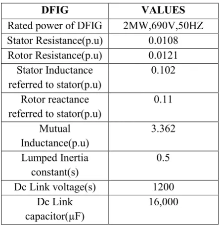
In this work, a 2 MW 690 V DFIG based variable speed WG system has been demonstrated to break down the transient dependability. The DFIG is associated with the system through a step up transformer and double circuit transmission lines as appeared in Figure 1. The sequence remunerating devices, i.e. the BFCL, or the SSFCL-LR, or the proposed R-type SSFCL is associated in sequence with one of the transmission lines. Transitory balanced and unbalanced faults were connected to the test system to assess the execution of R-type SSFCL. The parameters of DFIG [3] are appeared in Table I. The displaying of the wind turbine and DFIG is quickly clarified in underneath area.
Figure 1: Basic diagram of DFIG with the test study system
TABLE I:Parameters of the DFIG System
DFIG VALUES
Rated power of DFIG 2MW,690V,50HZ Stator Resistance(p.u) 0.0108 Rotor Resistance(p.u) 0.0121
Stator Inductance referred to stator(p.u)
0.102
Rotor reactance referred to stator(p.u)
0.11
Mutual Inductance(p.u)
3.362
Lumped Inertia constant(s)
0.5
Dc Link voltage(s) 1200 Dc Link
capacitor(µF)
16,000
A. Modeling of Wind Turbine
When all is said in done the extracted mechanical power by the wind turbine is given by [3].
( ) (1)
where, is the air density, R is the radius of the blade, is the wind speed, is the power coefficient which is a function of both tip speed ratio, λ, and blade pitch angle, β.
The term tip speed ratio can be defined as,
(2)
Where, is the rotational speed [rad/s]. For the wind turbine modeling, (λ, β) can be calculated as ,
( ) ( ) (3) Where,
* + (4)
B. Doubly-Fed Induction Generator Modeling
The Doubly-Fed Induction generator (DFIG) is an induction machine, where its stator is specifically associated with the grid, however the rotor winding is associated with the system through AC-DC-AC converter. The converter is isolated into two parts: Rotor-side converter (RSC) and Grid side converter (GSC). A dc-interface capacitor is associated between these two converters, so as to keep variety of the voltage in a little range. In this exploration, to control the RSC and GSC converters of the DFIG, the vector control technique is utilized [5].
C. Rotor Side Converter(RSC) Controller
In DFIG, the Rotor Side Converter (RSC) is associated with the generator rotor side as appeared in Figure 2(a). The principle reason for the RSC is control to the genuine and responsive energy of the DFIGs stator terminal [5]. The RSC is a power electronic full extension 2-level, 6-pulse converter. The electromagnetic torque can be controlled with the assistance of this 2-level, 6-pulse converter. Thus, it is conceivable to control the rotor speed of the generator, consequently the speed of the wind turbine. The RSC controller takes the terminal dynamic power, the responsive power, and terminal voltage as information sources and controls the output dynamic and the receptive power with the assistance of the controller.
D. Grid Side Converter(GSC) Controller
The primary target of the Grid Side Converter (GSC) is to keep up the dc-interface voltage consistent, irrespective of the rotor control [5].The GSC controller with pick up parameter esteems is appeared in Figure 2(b) and it is additionally a power electronic full extension 2-level, 6-pulse converter.
Figure 2. Configurations of: (a) RSC controller; and (b) GSC controller
It takes the information of dc interface voltage and the receptive power from the rotor line and sends the output by doing the important functioning, in this manner 2-level, 6-pulse converter can create the desirable pulse with the assistance of carrier frequency for the GSC converter. In this work, a carrier frequency is picked as 2700 Hz and a power capacitor of 16000 μF is utilized to smooth out the swell of the dc voltage and keep up consistent to 1200 Volts
III. RESISTIVE TYPE SOLID STATE FAULT
CURRENT LIMITER
A. R-type SSFCL configuration and operation
The design of the proposed single phase R-type SSFCL is the constituent part and is connected in shunt, shown in Figure 3(a). The extension part is made of four diodesD1toD4 and a dc reactor is connected in series
with a semi converter IGBT switch. The shunt branch comprises of a sidestep resistance and a ZnO arrester set in parallel with the extension part. In typical operation, the self-turn off device IGBT stays shut and the bridge part conveys the line current. For positive half cycle, the line current passes through D1 to D4 through IGBT
switch and dc reactor, and in negative half cycle current passes through D2 to D3 through IGBT switch and dc
reactor. The impedance of the parallel path is sufficiently high so that no Current will flow in normal condition
current will flow to the circuit and this sudden intrusion of high current can cause an over voltage into the circuit, which can harm the circuit. By utilizing ZnO arrester high voltage can avert and secure the circuit [6]. The fault is confined in the wake of opening the electrical switch, and afterward the system begins to recuperate and attempt to bring its normal condition. As the PCC voltage achieves its predefined reference voltage, the R-type SSFCL control system will be compelled to turn on the IGBT switch and the system will come back to normal operation.
In this paper, the shunt branch parameter ought to be picked in such way that SSFCL can expend to measure of energy which conveyed a similar measure of energy by the fault line in pre-fault time. After fault, the power ( ) devoured by the R-type SSFCL is as per the following:
(5)
Where, is the PCC voltage and is the shunt path resistance. The ideal esteem was discovered roughly 0.52 p.u., which gives the best execution.
B. R-type SSFCL Control Strategy
The control structure of the R-type SSFCL is appeared in Figure 3(b). During normal operation, the semiconductor switch is on and the dc current is passes through the dc reactor to the IGBT switch. Also, current is constantly contrasted and allowable current. In case of a fault, current ends up plainly more noteworthy than passable current. The control circuits detect it and open up the IGBT switch. After IGBT switch opens, the bridge part becomes isolated from the system and shunt path is connected to the faulted line which limits the fault current instantaneously. So another control parameter is needed to turn on the IGBT switch and return the bridge part in the operation. After a fault, while the IGBT switch is off, terminal voltage control is very important to maintain the system transient stability.
Figure 3. Configurations of: (a) The proposed single-phase R-type SSFCL schematic sequence; and (b) The
proposed R-type SSFCL controller.
So, the voltage at PCC point is considered to turn on the IGBT switch. When the value of has crossed over its predefined voltage value, the controller initiates the IGBT switch to be closed. Finally, the bridge section will be in operation mode and the system will come back to the normal operation of the system.
IV. MODELING OF BFCL AND CONTROL
STRATEGY
To demonstrate the viability of the proposed R-type SSFCL execution, its execution is contrasted with the BFCL. The BFCL circuit is shown in Figure 5(a). Fundamentally, the BFCL is made of diode bridge (D1
-D4), and a bypass current limiting reactor and resistor [3].
The point by point structure and operation of the BFCL is depicted in [3], both for ordinary and fault condition. A little estimation of the dc reactor () is considered in the BFCL which is (1mH). Rsh is the acquired resistance
of which is low as 0.1mΩ [3].On the other hand, for the execution examination between the R-type SSFCL and the BFCL similar controller is decided for BFCL as utilized as a part of R type SSFCL, and the control system is like R-type SSFCL controller.
V.
MODELING OF SSFCL-LR AND CONTROL
STRATEGY
Figure 4. Configurations of: (a) BFCL; (b) SSFCL- LR. device.
Then again, in [2], the shunt path comprises of inductive impedance and a variable resistance depicted in Figure 4(b). The points of interest of model and operation of the SSFCL-LR all around are clarified in this work. They demonstrated the variable resistance () of SSFCL-LR with the end goal that the estimation of the variable resistance fluctuates as indicated by varistor present and nominal line current.
VI. FUZZY LOGIC CONTROLLER (FLC)
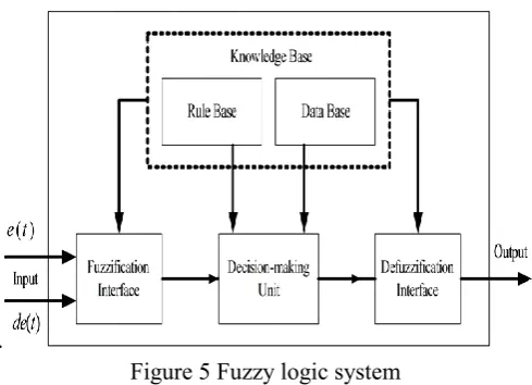
Fuzzy Logic Controller is one of the most successful applications of fuzzy set theory. Its major features are the use of linguistic variables rather than numerical variables. The basic structure of the FLC is shown in Fig 5.
The fuzzifier converts input data into suitable linguistic values by using fuzzy sets. The fuzzy sets are introduced with membership functions like triangle, sigmoid, trapezoid. The knowledge base consists of a data base with necessary linguistic definitions and control rule set. The rule set of knowledge base consists of some fuzzy rules that define the relations between inputs and outputs. Inference engine simulates the human decision process. This unit infers the fuzzy control action from the knowledge of the Control rules and the linguistic variable definitions. Therefore, the knowledge base and the inference engine are in interconnection during the control process.
Firstly active rules are detected by substituting fuzzified input variables into rule base. Then these rules are combined by using one of the fuzzy reasoning methods. Max-Min and Max-Product are most common fuzzy reasoning methods. The defuzzifier converts the fuzzy control action that infers from inference engine to a non fuzzy control action.
.
Figure 5 Fuzzy logic system
There are three variables of the FLC they are error, the change in error and the change in output and FLC is having seven triangle membership functions for each variable. The basic fuzzy sets of membership functions for the variables are as shown in the Figs. 5a, 5b and 5c. The fuzzy sets are expressed by linguistic variables positive large (PL), positive medium (PM), positive small (PS), zero (Z), negative small (NS), negative medium (NM), negative large (NL), for all three variables. A rule in the rule base can be expressed in the form: If (e is NL) and (de is NL), then (co is NL). The rules are set based upon the knowledge of the system and the working of the system. The number of rules can be set as desired. The numbers of rules are 25 for the seven membership functions of the error and the change in error (inputs of the FLC).
Figure 5b. Membership functions of change in error
Figure 5c. Membership functions of controlled output
TABLE: Rule Base of Fuzzy Logic Controller
e/∆e NL NS ZE PS PL
NL NL NL NM NS ZE
NS NL NM NS ZE ZE
ZE NM NS ZE PS PM
PS NS ZE PS PM PL
PL ZE PS PM PL PL
VII.
SIMULATION RESULTS WITH
EXPLANATION
In this work, during the fault the wind speed is assumed to be 11 m/s and power factor is unity. For enhancing transient stability of proposed system, a temporary 3LG, 2LG and 1LG faults are applied at point F1 at 0.1s in
double circuited line. The faulted line having circuit breakers CB1 and CB2. They will be open at 0.2s successfully just after applying the fault. Reclosing time of CB's is 1.2s.The simulation results time span is considered to be in between 0 and 2sec.
Four different cases are considered i.e with no controller ,with BFCL and LR-SSFCL, proposed R-type SSFCL with fuzzy controller.
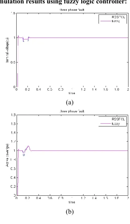
A. TRANSIENT STABILITY ANALYSIS FOR SYMMETRICAL FAULT (3LG)
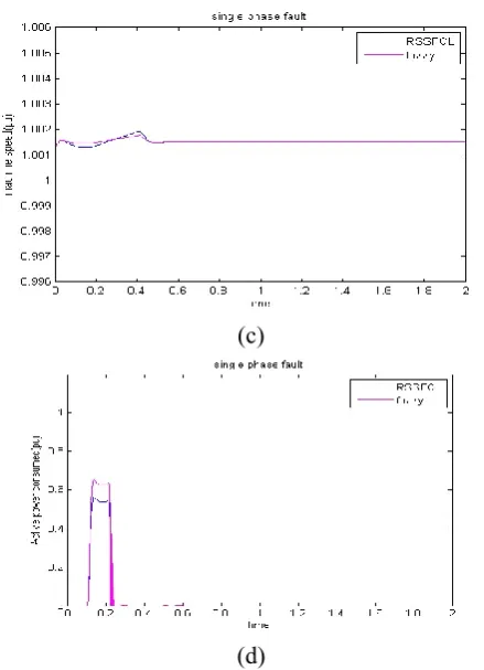
During the 3LG fault, the voltage of system reduced to zero i.e without any controller in the system .By using R-type SSFCL with fuzzy controller the voltage of system is maintained in + 0.1 p.u of nominal value and returned to rated value in short interval of time. The performance is depicted in simulation response curves of terminal voltage, active power, machine speed, active power consumed is shown in Figure 6(a) to (d).
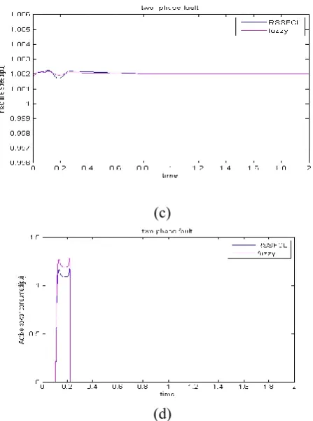
B. TRANSIENT STABILITY ANALYSIS FOR UNSYMMETRICAL FAULTS (2LG,1LG)
During unsymmetrical faults ,system performance in terminal voltage, active power, machine speed, active power consumed are improved by using R-type SSFCL with fuzzy controller. Simulation curves are shown in fig 7 (a) to (d) and Figure 8 (a) to (d).
Simulation results using fuzzy logic controller:
(a)
(c)
(d)
Figure 6. Simulation results of DFIG for 3LG fault: (a) Terminal voltage; (b) Output active power; (c) Speed; (d) Absorbed power by the devices.
(a)
(b)
(c)
(d)
Figure 7. Simulation results of DFIG for 2LG fault: (a) Terminal voltage; (b) Output active power; (c) Speed; (d) Absorbed power by the devices.
(a)
(c)
(d)
Figure 8. Simulation results of DFIG for 1LG fault: (a) Terminal voltage; (b) Output active power; (c) Speed; (d) Absorbed power by the devices.
VIII.
CONCLUSION
In this paper, the proposed R-type SSFCL with fuzzy logic controller structure, simulation comes about with point by point clarification is displayed. It is extremely viable in wind control systems to improve the transient stability by moderating the voltage list and fault current. Additionally, it keeps the machine speed during a fault, in this way DFIG confronts low anxiety and enhances the transient stability. The R-type SSFCL with fuzzy logic controller can keep up the output control easily and successfully by expending the active power during the fault time. At long last, it is apparent from simulations proposed R-type SSFCL with fuzzy logic controller is more effective in upgrading transient stability than the R-type SSFCL with PI controller, BFCL and SSFCL-LR in all aspects during both balanced and unbalanced fault in the power network.
IX. REFERENCES
[1]. M. M. Husain, and M. H. Ali, "Future research directions for the wind turbine generator system" Renewable and Renewable Energy Reviews, vol.49, 481–489, 2015.
[2]. M. H. Ali, Wind Energy Systems: Solutions for Power Quality and Stabilization, First. Florida, USA: Taylor & Francis Group, CRC Press, 2012. [3]. G. Rashid, and M. H. Ali, "Transient Stability
Enhancement of Doubly Fed Induction Machine-Based Wind Generator by Bridge-Type Fault Current Limiter," IEEE Transaction on Energy Conversion, vol.PP, no. 99, pp. 1–9, Feb. 2015. [4]. A.Fereidouni, M. A.Masoum, T.Hosseinimehr,
and M. Moghbel, "Performance of LR-type solid-state fault current limiter in improving power quality and transient stability of power grid with wind turbine generators" International Journal of Electrical Power & Energy Systems, 74, 172-186,2016.
[5]. J. Mohammadi, S. Vaez-Zadeh, S. Afsharnia, and E. Daryabeigi, "A Combined Vector and Direct Power Control for DFIG-Based Wind Turbines," IEEE Trans. Sustain. Energy, vol. 5, no. 3, pp. 767–775, Jul. 2014.