A PARAMETRIC STUDY OF ALTERNATIVE
SUPPORT SYSTEMS FOR CYLINDRICAL GRP
STORAGE VESSELS
D H Nash, W M Banks, A S Tooth and A E Flaherty
Department of Mechanical Engineering, University of Strathclyde 75 Montrose Street, Glasgow, Scotland, UK:[email protected]
SUMMARY:
Support systems for static and transportable glass reinforced plastic pressure vessels have been investigated using both experimental and analytical methods. Traditional designs have been based on twin saddle-type supports, fixed or free at the base, and loose or attached to the shell surface. While this tried and well-proved approach is common in industry, the vessel wall remains subject to significantly high tensile and compressive strain levels in the region of the saddle horn juncture.
Alternatives, such as the flexible sling support or longitudinal beam systems have been examined. It has been shown that high strain levels in the vessel wall can be dramatically reduced for certain cases. However, strain redistribution takes place and other, previously low strain regions become important and dominate the overall design.
A parametric study has been undertaken and results are presented for both the flexible sling and the longitudinal beam support. In addition, detailed studies of the strain redistribution and solutions for overcoming high strain regions are documented.
Lastly, guidance is given for designers on the best support configuration selection for achieving an optimal design support system.
KEYWORDS: storage vessels, support systems, parametric study, optimal design, laminated shells, glass reinforced plastics
INTRODUCTION Background
Horizontal glass reinforced plastic (GRP) storage vessels are used principally when weight and corrosion resistance are influencing factors. Vessels are usually fabricated in accordance with national standards such as BS4994 [1], using a layered construction technique with fibres being oriented to maximise the strength of the cylinder in resisting the hydrostatic pressure exerted on the shell wall. The manufacturing process involves fibres being laid over a mandrill to form the cylinder, with pre-formed chopped strand mat (CSM) torispherical ends being used to close the vessel. This results in the inner surface dimensions being exact and imperfection free whilst the outer surfaces have irregularities.
For GRP vessels, twin saddle supports, symmetrically placed and giving a statically determinate system are used in preference to multi-support systems where differential settlement and indeterminancy may result. The use of rigid saddles for the support of liquid-filled vessels produces high values of radial interface pressure at the uppermost point of the
ACCM-3 (2002)
The 3rd Asian-Australasian Conference on Composite Materials
Auckland, New Zealand 31 Jan. ~ 2 Feb. 2002
saddle, the ‘horn’, which generates localised high strains in the vessel material. Peak strains that occur in the region of the saddle horn are compressive on the outer surface and tensile on the inner [2]. If the magnitude of the inner surface tensile strains becomes excessive, typically greater than 2000, local cracking may occur. This can lead to liquid ingress to the glass resulting in premature failure by stress corrosion cracking. This failure mode is attributed to the support of the relatively flexible vessel on the rigid saddle, which produces high strains in the horn region. Modern design codes attempt to address this by tailoring the laminate properties of the material to account for the rigid supports, rather than the requirements for storage of the intended contents.
Aims of the Present Work
The present work aims to address the highly localised strains that occur when using twin saddles. These strains can be reduced by the use of flexible supports. Although previous researchers [3,4] achieved some success in reducing strain by employing a rubber interface between the rigid saddle and the vessel wall, a preferred route may be the adoption of a new approach. Two specific support systems have been fully examined analytically using finite element methods and as part of a wide ranging experimental programme employing three full sized GRP vessels. These alternative systems comprising a twin flexible sling arrangement and a twin longitudinal beam support system have been considered and have shown promising results in reducing the high strain levels previously observed when using saddles. This paper examines the important parameters that must be considered when using these alternative support systems. In addition, selected results from a full parametric study are presented together with guidance for designers.
ALTERNATIVE SUPPORT SYSTEMS
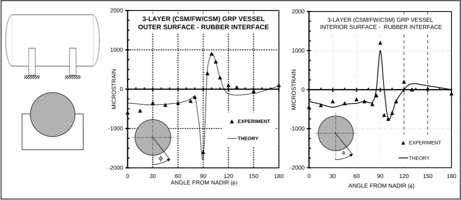
[image:2.595.67.528.505.705.2]The need for an alternative support system for horizontal twin saddle supported storage vessels is apparent when considering a typical strain distribution present in the vessel wall [5].
Fig. 1 Twin saddle supported vessel with typical strain distributions
Fig.1 shows the strain distribution for a typical 3-layer system, comprising one layer of filament wound (FW) material surrounded on either side by a layer of chopped strand mat
3-LAYER (CSM/FW/CSM) GRP VESSEL OUTER SURFACE - RUBBER INTERFACE
-2000 -1000 0 1000 2000
0 30 60 90 120 150 180 ANGLE FROM NADIR (
MI CRO ST RAI N EXPERIMENT THEORY
3-LAYER (CSM/FW/CSM) GRP VESSEL INTERIOR SURFACE - RUBBER INTERFACE
-2000 -1000 0 1000 2000
0 30 60 90 120 150 180 ANGLE FROM NADIR ()
MICRO
STRAIN
EXPERIMENT
(CSM) material. The observed distribution of strain, from experimental and analytical studies of a rigid saddle with rubber interface undertaken by the authors, clearly shows the influencing peak strain present at the saddle horn. In addition, the changing sign of strain from inside to outside surface indicates there is significant bending present. This occurs just as the vessel wall moves from a state of rigid support, with a high interface contact pressure, to a free state with no reacting pressure present. The peak nature of the distribution dies out over a short distance in the vessel under the saddle but exists for more than twice the distance on the free side. This strain distribution dominates the design process and results in thicker vessel walls and therefore, alternatives must be considered which reduce or eliminate the maximum strain values.
Flexible Slings
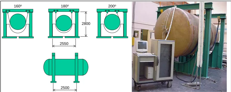
Flexible sling supports comprise two or more slings suspended freely from a frame, which allows radial movement to occur. The lifting sling was manufactured from Duplex high-tenacity polyester, which, on testing, had a Young’s modulus of 4GPa. The slings were attached to the frame by beam clamps that traverse the frame allowing a range of support angles to be investigated. The influence on strain of the sling width can only be examined by the use of wider or narrower slings. Previous work by the present authors [6] employed Kevlar slings, with a different clamping system, which ultimately resulted in a failure. Hence the low cost lifting slings with a portal frame was used for all current experiments. Flexible slings also have the advantage of free movement and hence can be used to accommodate large thermal expansions or help eliminate problems associated with excessive vibration.
2500 2550
2800
180o 200o
160o
[image:3.595.67.527.405.588.2]
Fig. 2 Portal frame and sling support arrangement
Longitudinal Beams
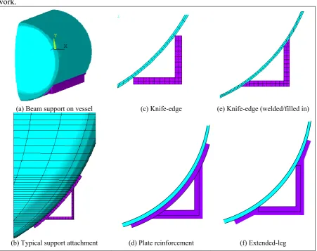
show a number of alternative connection styles, which were examined during the present work.
(a) Beam support on vessel (c) Knife-edge (e) Knife-edge (welded/filled in)
[image:4.595.75.527.90.447.2](b) Typical support attachment (d) Plate reinforcement (f) Extended-leg
Fig. 3a-f Vessel with longitudinal supports and various support connection styles
EXPERIMENTS AND ANALYSIS
Flexible Slings
Experimental Programme
Three full size vessels were fully strain gauged (240 gauges) and systematically hydro-tested to examine the strain distributions on both inside and outside surfaces. The vessels comprised one 16mm thick isotropic CSM vessel, one 3-layer 10mm thick CSM/FW/CSM vessel and one 5-layer 10 mm thick vessel CSM/FW/CSM/FW/CSM configuration.
Analytical Approach
Fig. 4 Finite element representation and maximum strain position (5 layer vessel)
Flexible sling results
Supporting the vessels with a 200mm wide sling and an initial saddle wraparound angle of 180, the maximum strain was found to move some –5 to –10 from the previous saddle horn position i.e. the maximum lies within the flexible sling wraparound, Fig 4. In the region of the support however, the results obtained from sling-strap supported vessels indicate an improvement compared with the rigid twin-saddle supports. For the isotropic vessel, using sling-strap supports the outer-surface maximum strain increases by 14% (less critical since compressive) compared with the rigid saddle but the inner-surface tensile strain reduces by 50%. In the case of the laminated vessels, a reduction in both the outer and inner surface strains is observed. When considering the outer surface strains of the sling-strap compared with the rigid saddle a reduction of 22% is identified for the 3-layer vessel and a reduction of 40% for the 5-layer vessel. The inner surface tensile strains for both vessels show a reduction of around 60% comparing sling-strap supports to the rigid saddle.
Longitudinal Beams
Experimental Programme
- Indicates strain-gauge location
6
12 6
1 5
4
3 2
1
D C B A
A – Beam End
[image:6.595.69.529.70.315.2]B – 100mm from beam end C – Saddle/sling centre line D – Vessel mid-span
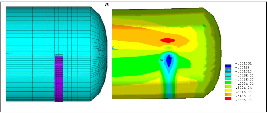
Fig. 5 Finite element representation and maximum strain position (5 layer vessel)
Analytical Approach
Using a 3D finite element model with the angle and beam support fully connected, a full examination of possible connection styles was undertaken. Since all components were fully connected, there was no requirement for a non-linear contact analysis. Initially, the beam length was considered to terminate at the end of the cylindrical section, see Fig 3a. However, preliminary studies indicated that the maximum strain moved to this location. A further modification to both the finite element model and thereafter, to the experimental vessel, was the addition of an end wraparound extension, see Fig 6. The wraparound thus continues the beam along the cylinder and around the knuckle region of the dished end. For the test vessel, the wraparound must be manually profiled to provide adequate fit around the end region.
[image:6.595.67.528.508.741.2]
Longitudinal beam support results
The maximum strain for the longitudinal beam consistently occurs at profile B as shown in Fig 5. The magnitude of the maximum strain is, of course, lower in the region of the saddle horn but remains high due to the sudden transition from support to no-support at the beam end. In addition, from the experimental programme, it is necessary to ensure good fit between the angle section and the beam, otherwise imbalance occurs between the two sides and higher strains result. In order to address the end effects, the wraparound shown in Fig 6 was applied and the vessel re-tested and re-analysed. A reduction of more than 25% in the maximum measured strain results when a full wraparound is applied, compared with the original saddle, extending to the crown of the end. Reductions in strain were also observed even with a modest wraparound applied.
PARAMETRIC STUDIES
In order to provide useful information to designers, a parametric study was undertaken both experimentally and analytically for both the flexible sling and also the longitudinal beam support systems. For the purposes of comparison, the 5-layered vessel was used.
Flexible Sling Study
For a given set of vessel parameters, radius, thickness and length, the main parameters under consideration associated with the flexible sling comprise, wraparound angle , sling width b,
sling position from vessel end A, and sling material.
Table 1 Parameters used in flexible sling strap study
Variable Values applied
Sling width b 100, 200, 300, 400,800 and 2000mm†
Sling position A 400, 500, 750, 1000, 1250mm ††
Support angle 120, 140, 160, 180 and 200
Sling material Polyester, steel †††
† Represents full parallel length of vessel (half-model) †† Sling width 200mm
††† Remaining parameters as defined by experiment
Effect of sling width, b
Considering the parameters in turn, varying the sling width results in an increased area over which the load is distributed. With a narrower sling however, the maximum strain aligns itself with the sling edge, this depending on the distance from the end of the vessel. If the sling is located near the end, then the maximum strain is at the inner edge of the sling, facing the vessel mid-span. If the sling is located at the quarter points, then the maximum is at the centre of the sling. Since the radius, R of the vessel was 1m, the b/R ratio varies from 0.1 to 2
respectively, with 0.2R being the default test value. Widths less than 0.2R show a rapid
increase in strain whilst widths greater than 0.2R give lower values, Fig 7a. However widths
greater than 0.5R prove to have little benefit for increased width. British Standard BS4994
-2000 -1000 0 1000 2000
0 1000 2000 3000 4000 SLING-STRAP WIDTH (mm)
MI
CROSTRAI
N
(
)
Inner surface tensile strain Outer surface compressive strain
-2000 -1000 0 1000 2000
0 500 1000 1500
SLING-STRAP POSITION RELATIVE TO END (mm)
MICROSTRAIN (
)
[image:8.595.68.529.71.289.2]Inner surface tensile strain Outer surface compressive strain
Fig. 7a,b Maximum strain for various sling widths (b) and sling positions (A)
Effect of sling position, A
With steel vessels, where the ends provide significant stiffening, a large reduction in stress is found when moving the support near the end. With GRP vessel, the end is more flexible due to the difference in Young’s modulus compared with steel, for the same shape. This is reflected in Fig 7b, where a slight reduction is observed as the 0.2R wide sling moves towards
the end.
Effect of sling wraparound angle,
Six wraparound angles were considered. The 120 angle represents the same angle recommended for rigid steel saddles. The 180 wraparound provides one quarter of the total vessel weight being supported directly through the sling, this being the lowest load for any support angle. Intermediate cases were considered. An extra case of 200 was studied to see the effect of extra support, maintaining the circularity beyond 180. The strain distribution was similar for all cases. The maximum strain was high was small wraparound angle but only reduced by a few percent for those increments between 160 and 200 degree cases. As indicated previously, the tensile strains were reduced in all cases when compared to rigid supports.
Effect of material
The effect of sling material can be observed by considering woven polyester straps and steel straps which introduce a degree of rigidity in the support surface comparable to the saddle-support. From the results obtained, Table 2 shows little difference in the magnitude of peak compressive strain showing a 7% increase for steel sling-straps compared with polyester. There is an increase by 50% at the inner surface comparing the steel sling-strap to the polyester, though the magnitude of strain is much lower than the design guideline of 2000με. It can be concluded that changing the support material has little influence in the level of compressive strain attained, since radial displacement is still possible but shows that the a flexible-to-flexible arrangement reduces the important inner surface tensile strains.
Table 2 Results from varying sling-strap material
Sling material Outer surface Compressive Strain ()
Inner surface Tensile strain ()
Polyester -1561 249
Steel -1681 377
Longitudinal Beam Study
Undertaking a full parametric study where longitudinal beam supports are being considered is somewhat impracticable as variations in maximum strain depend significantly on the support interface. However, from earlier studies reported herein, the maximum strain in the cylindrical vessel wall, recorded when using longitudinal supports is lower than that for other support styles. The maximum strain is found at the longitudinal beam end. Therefore, by the use of an end wraparound which lowers the overall strain level, there is considerable opportunity to reduce the wall thickness of the main shell, which was previously designed on the basis of minimising strains in the cylinder, not the end. Table 3 details the new designs that were considered as an alternative to the 5-layer vessel used in the experiment. Each laminate employs a symmetric lay-up and the lengths are generally longer than the experimentally tested vessel.
Table 3 Laminate configuration adopted for beam support parameter study
Laminate Reference
Laminae Thickness (mm) Final Laminate
Thickness (mm) Layer 1
CSM Layer 2 FW 55 Layer 3 CSM Layer 4 FW 55 Layer 5 CSM
DES5_1 1 1 1 1 1 5
DES5_2 1.5 0.5 1 0.5 1.5 5
DES6_1 1 1.5 1 1.5 1 6
DES6_2 1.5 1 1 1 1.5 6
DES6_3 1.5 0.75 1.5 0.75 1.5 6
DES7_1 1 2 1 2 1 7
DES7_2 1.5 1.25 1.5 1.25 1.5 7
DES7_3 2 0.5 2 0.5 2 7
DES7_4 0.5 2.75 0.5 2.75 0.5 7
LENGTH is applied for all laminates defined above
LENGTH mm 4000 5000 6000 7000 8000
[image:9.595.84.508.386.651.2]CONCLUSIONS
Using full size experimental vessels in combination with appropriate finite element models has allowed a parametric study of alternative support styles for GRP vessels to be undertaken. The two alternatives to rigid saddles considered have been flexible sling and longitudinal beams. Each support style has specific benefits in the reduction of the maximum strain with respect to the rigid saddle. However, these benefits come at the expense of additional alternative support structures. It may not always be possible to incorporate these due to other restrictions. Both alternatives generate lower maximum vessel strains, which provides an opportunity for thinner and lighter vessels. It is noted that the flexible slings in general produce lower tensile strains on the inner surface. If flexible slings are to be used, locating them nearer the end provides maximum benefit. For shorter thinner vessels where larger displacements are present or axial movement is required, flexible slings are recommended. For longer moderately thick vessels (L/R>5), longitudinal beam supports, which have the
lowest overall strain distribution, present a viable alternative to rigid twin saddles. If longitudinal beam supports are to be employed, care must be made to ensure good fit along the vessel length, otherwise an imbalance on load transfer results.
ACKNOWLEDGEMENTS
The authors wish to note the major contribution made by Emeritus Professor Alwyn S Tooth to this on-going research topic. Professor Tooth passed away during the completion of this work.
REFERENCES
1. BS4994:1987 “Design and construction of vessels and tanks in reinforced plastics”, British Standards Institution
2 Tooth, A. S., Banks, W. M., Seah, C. P. & Tolson, B. A., “The twin-saddle support of horizontal multi-layered GRP vessels – theoretical analysis, experimental work and a design approach.” Proceedings of the Institute of Mechanical Engineers Part E Journal of Process Mechanical Engineering, 208 (E1) pp59-74 (1994)
3 Tooth, A. S., Warrender, A. J. & Banks, W. M. “A design procedure for horizontal cylindrical vessels supported on twin-saddles”, Sixth International Conference for Composite Materials (ICCM) and Second European Conference (ECCM), London UK
Vol.5 pp5.123-5.133 (1987)
4 Seah, C.P. “An experimental study of the support of laminated GRP horizontal vessels” MPhil thesis, University of Strathclyde, Glasgow UK (1993)
5 Nash, D. H., Flaherty, A. E., Banks, W. M., Fok, W. C. & Tooth, A. S. “The design of twin-saddle supported multi-layered glass-reinforced plastic vessels – the development of a parametric equation for the maximum strain.” Proceedings of Institution of Mechanical Engineers Vol.214 Part L pp113-128 (2000)
6 Banks, W. M., Tooth, A. S. & Ong, L. S. “The support of horizontal multi-layered GRP vessels – saddles, slings or longitudinal beams?”, Second International Conference on Pressure Vessel Technology (ICPVT-2), pp315-322 (1992) (American
Society of Mechanical Engineers, New York)