UNIVERSITI TEKNIKAL MALAYSIA MELAKA
DESIGN AND DEVELOPMENT OF AN OPTIMISED
THERMOELECTRIC COOLER FOR ACTIVE PROCESSOR
COOLING
This report submitted in accordance with requirement of the Universiti Teknikal Malaysia Melaka (UTeM) for Bachelor Degree of Manufacturing Engineering
(Design) (Hons.)
by
NAZRIN B MOKHTAR B051210198 910311-06-5817
DECLARATION
I hereby, declared this report entitled “Design and Development of an Optimized Thermoelectric Cooler for Active Processor Cooling” is the results of my own
research except as cited in references.
Signature : ……….
Author’s Name : ……….
Date : ……….
APPROVAL
This report is submitted to the Faculty of Manufacturing Engineering of UTeM as a partial fulfillment of the requirements for the degree of Bachelor of Manufacturing Engineering (Manufacturing Design) with Honours. The member of the supervisory committee is as follow:
(Signature of Supervisor)
ABSTRACT
ABSTRAK
DEDICATION
ACKNOWLEDGEMENT
First of all, thanks to Allah s.w.t for all His guidance and blessing through all the hardship encountered whilst completing this project paper. In preparing this project paper, I was in contact with many people, researchers, academicians and practitioners. They have contributed towards my understanding and thoughts. In particular, I wish to express my sincere appreciation to my main supervisor, Dr. Zulkeflee bin Abdullah and my panels Prof. Madya Dr. Engr. Hambali bin Arep and Dr. Shajahan bin Maidin for encouragement, guidance, critics and friendship.
I would like to thank my beloved family who always encourage me and their loving bless. I am also indebted to FKP lecturers for their guidance to complete this project paper. Without their continued support and interest, this project paper would not have been presented here.
TABLE OF CONTENT
Abstract ii
Dedication iii
Acknowledgement iv
Table of Content2 v List of Tables vi
List of Figures vii List of Abbreviations, Symbols and Nomenclatures viii
CHAPTER 1: INTRODUCTION 1
1.1 Background 1
1.2 Problem Statement 3
1.3 Objective of the Project 3
1.4 Scope of Project 3
CHAPTER 2: LITERATURE REVIEW 4
2.1 Introduction 4
2.2 Thermoelectric Cooler 4
2.2.1 Thermoelectric Cooler Theory 5
2.2.2 Thermoelectric Cooler Construction 5
2.2.3 Thermoelectric Cooler Specification 7
2.2.4 Thermoelectric Cooler Calculation 7
2.2.5 Thermoelectric Cooler Advantages 8
2.3 Design Approach of Thermoelectric Cooler Module 8
2.3.1 Direct Die Heat Sink TEC 8
2.3.2 Direct Die Liquid Cooling TEC 9
2.3.3 Chiller TEC 10
2.4 Controller 11
2.4.1 Thermostat 11
2.4.2 Pulse-Width Modulation 12
2.4.3 PID Controller 12
2.4.5 MOSFET 14
2.4.6 Temperature Sensor 14
2.4.7 Temperature Sensor LM35 15
2.4.8 LCD Display IIC LCD2004 – HD44780 16
2.5 Material Selection for Thermal Transfer 17
2.5.1 Material Thermal Conductivity 18
2.5.2 Galvanic Corrosion 18
CHAPTER 3: METHODOLOGY 20
3.1 Introduction 20
3.2 Project Methodology 20
3.3 Project Flow Chart 21
3.4 Identification 22
3.5 Design Requirement 23
3.6 Concept Generation 23
3.7 Concept Development 24
3.7.1 Concept 1 24
3.7.2 Concept 2 25
3.7.3 Concept 3 26
3.8 Design Concept Selection 27 3.8.1 Selection Criteria 29
3.8.2 Rate the Concept 29
3.8.3 Concept Screening 30
3.8.4 Concept Scoring 31
3.8.5 Combination of Concept 32
3.8.6 Final Concept 32
3.9 Working Flowchart of the System 33
3.10 Controller Working Flowchart 34
3.11 Energy Efficiency & Power Consumption 35
CHAPTER 4: RESULT 39
4.1 Introduction 39
4.2 Proof of Concept 39
4.3 Proof of Concept Rendering 40
4.4 Prototype for the Proof of Concept 42
4.5 Final Prototype Rendering 44
4.6 Controller Circuit Schematic 46
4.7 Controller Programming 47
4.8 Controller Hardware 48
4.9 Final Prototype 49
4.10 Final Prototype Benchmarking 50
CHAPTER 5: DISCUSSION 52
5.1 Introduction 52
5.2 Proof of Concept 52
5.3 Proof of Concept Analysis 54
5.4 Final Prototype Improvement 55
5.5 Controller Coding Explanation 56
5.6 Final Prototype Benchmark 60
CHAPTER 6: CONCLUSION 61
6.1 Conclusion 61
6.2 Suggestion 61
i
LIST OF TABLES
Table 2.1: Temperature Sensor Comparison 15 Table 3.1: Gantt chart of the project for semester 1 22 Table 3.2: Gantt chart of the project for semester 2 22
Table 3.3: Concept 1 24
Table 3.4: Concept 2 26
Table 3.5: Concept 3 27
Table 3.6: Engineering design specification of the thermoelectric cooling system 29
Table 3.7: Concept rating 30
Table 3.8: Concept screening 30
Table 3.9: Relative score for concept scoring 31
ii
LIST OF FIGURES
Figure 1.1: 35 Years of microprocessor trend data 2
Figure 2.1: Thermoelectric module theory 5
Figure 2.2: Basic construction of a single-stage TEC 6 Figure 2.3: Schematic of CPU cooled by direct die TEC heat sink 9 Figure 2.4: Schematic of direct die liquid cooling 9 Figure 2.5: Schematic liquid chiller thermoelectric 10
Figure 2.6: Arduino Uno Board layout 13
Figure 2.7: N-Channel MOSFET 14
Figure 2.8: LM37 layout interface to microcontroller 16 Figure 2.9: Picture of IIC LCD2004-HD44780 display module 17
Figure 2.10: Thermal conductivity chart 18
Figure 2.11: Galvanic series of some commercial metals and alloys in underwater 19
Figure 3.1: Concept 1 24
Figure 3.2: Concept 2 25
Figure 3.3: Concept 3 26
Figure 3.4: System flowchart 33
Figure 3.5: Controller flowchart 34
Figure 3.6: C.O.P vs V 35
Figure 3.7: TEC calculator 100% voltage 36
Figure 3.8: TEC calculator 14% voltage 37
Figure 3.9: Solidworks 2015 38
Figure 4.1: Top view of Proof of Concept Manifold 40
Figure 4.2: Bottom view of Proof of Concept Manifold 40
iii
Figure 4.4: Bottom view of Proof of Concept Cold Plate 41
Figure 4.5: Top view of Proof of Concept Cold Plate 41
Figure 4.6: Assembled view of Proof of Concept 41
Figure 4.7: Proof of Concept Prototype 42
Figure 4.8: Proof of Concept Bench Test 43
Figure 4.9: Result for Proof of Concept 43
Figure 4.10: Top view of Final Prototype Manifold 44
Figure 4.11: Bottom view of Final Prototype Manifold 44 Figure 4.12: Top view of Final Prototype Hot Plate 44 Figure 4.13: Top view of Final Prototype Cold Plate 45 Figure 4.14: Bottom view of Final Prototype Cold Plate 45
Figure 4.15: Assembled view of Final Prototype 45
Figure 4.16: Circuit Schematic 46
Figure 4.17: Controller Hardware 48
Figure 4.18: Top view of the Final Prototype 49
Figure 4.19: Bottom view of the Final Prototype 49
Figure 4.20: Benchmarking Result 50
Figure 4.21: Temperature Reading of the TEC Cooler at 100% Load 50
Figure 4.22: Benchmarking Setup 51
Figure 4.23: Benchmarking Setup 2 51
Figure 5.1: Result for Proof of Concept 52
Figure 5.2: TEC Calculator 46% voltage No-Load 53
Figure 5.3: Ice forming when it reaches sub-zero temperature 54
Figure 5.4: LCD reading under load condition 59
1
Chapter 1
Introduction
1.1 Background
Modernisation has brought the advancement of central processing unit to a higher stage compared to the last few decades. Basically a central processing unit is an electronic chip in a computer that carries out the instruction of a computer program by performing the basic arithmetic, logical, control and input/output operation specified by the instructions. The design, form and application of central processing unit have changed over the course of history, but their fundamental operation remains unchanged.
Nowadays most modern central processing unit is called microprocessors, which mean that they are contained in a single integrated circuit. Over the course of history the advancement of central processing unit technology, the density of transistor increases as the advancement in semiconductor bring smaller transistor to into integrated circuit. According to Gordon E. Moore, the transistor count of an integrated circuit doubles approximately every two years. In 2014, the highest transistor count found in commercial central processing unit is over 4.3bilions transistor, in Intel i5-core Xeon. (Moore & Fellow, 1998)
2
fracture, corrosion) and electrical (overstress, migration and diffusion, gate oxide breakdown) Following the Arrhenius equation, (for die temperatures operating in the range of -20ºC to 140ºC) every 10ºC decrease in temperature reduces the failure rate by approximately a factor of 2. We can therefore expect a reduction in chip failure rates with lower operating temperatures ( Davis et al., 2006)
[image:15.595.153.499.321.534.2]Typically heat sinks with a blower (air cooling) are attached on top of the central processing unit. However due to increasing heat load some user have opted to liquid cooling, in which the central processing unit are cooled by liquid that passed through a water block on top of the central processing unit. The liquid would be cooled down by a radiator. However liquid cooling are restricted due to the heat load they can pull.
Figure 1.1: 35 Years of Microprocessor Trend Data (Sam Naffziger, AMD)
3
1.2 Problem Statement
The growth in central processing unit heat generation has sparked attention in active cooling to bring the temperature down. Critical application of central processing unit in servers or a high performance computer requires an advanced cooler mechanism that would bring the temperature down to an optimum level. Thus, thermoelectric cooler would be needed to assist the cooling down of the central processing unit. However, there are many problems plaguing thermoelectric cooler. They are notoriously known for their high power consumption, high power dissipation, low coefficient of performance (C.O.P) and limitation due to inefficient system used. Thus in this project it would be covering the optimisation of the thermoelectric cooler cooling module for active central processing unit cooling.
1.3 Objective of the Project
There are three objectives that need to be achieved in this project, and they are:
i. To design an optimized thermoelectric cooler cooling module for active central processing unit cooling.
ii. To develop an optimized thermoelectric cooler cooling module for active central processing unit cooling.
iii. To evaluate the performance of the thermoelectric cooler cooling module.
1.4 Scope of Project
The scope of the project is focused on the following area:
i. Design and Analysis in Solidworks Software.
ii. Fabrication of the thermoelectric cooler cooling module.
4
Chapter 2
Literature Review
2.1 Introduction
In this project, the literature review serves as guide for the project. It contains the related information to proceed with the designing, analysing and the fabrication of the thermoelectric cooler cooling module prototype. In this chapter, we would be covering the thermoelectric cooler principles, design approach of the cooler, Arduino controller and the related item that would be used during the course of the project. Design approach refers to the integration of thermoelectric cooler into the cooling system of the central processing unit.
2.2 Thermoelectric cooler
5
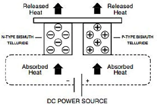
2.2.1 Thermoelectric Theory
[image:18.595.190.450.294.468.2]When direct current (DC) voltage are applied to the module, the positive (+ve) and negative (-ve) charge carriers in the pellet array would absorb heat from one side of the ceramic plate and releases it to the opposite side of the ceramic plate. Consequently the surfaces in which the heat is absorbed become cooler and the opposite side in which the heat is released becomes hotter. When the polarities of the voltage are reversed it would result in the reserved hot and cold side. (Goupil et al., 2011)
Figure 2.1: Thermoelectric module theory (Source: V-Infinity)
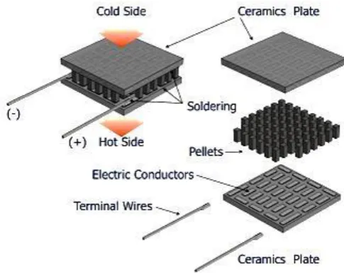
2.2.2 Thermoelectric cooler Construction
The thermoelectric coolers are composed of thermoelectric couples that are connected in series. They are enclosed in a ceramic plated that is sandwiched between them, in which they are parallel thermally. The two sides of the ceramic plates would be the hot or the cold side of thermoelectric cooler.
Generally, the thermoelectric cooler consisted of the following parts:
6
material due to the complex optimal thermoelectric performance and technological properties.
ii. Ceramic Plates – used to provide mechanical integrity of the thermoelectric cooler. They must be able to satisfy the requirement of electrical insulation from an object to be cooled and the heat sink. Apart from that the plate must have a good thermal conductance to provide heat transfer with minimal resistance. Commonly aluminium oxide ceramic are used due to the optimal cost to performance ratio.
iii. Electrical Conductors – used to provide serial electric contacting of the pellet with each other and to establish contact with the leading wire. Usually on a high powered module they are made of copper tab to reduce resistance.
iv. Soldering – provides assembling of the thermoelectric cooler module. Commonly the solder used includes antimony-tin and lid-tin alloys. The solder are crucial as they are the limiting factor of operation of the module. This is because high temperature would melt the solder and damages the thermoelectric cooler module. Thus the operating temperature must be lower than the solder’s melting point.
[image:19.595.195.438.490.682.2]v. Terminal Wires – provides connection from the ending conductor to the direct current (DC) electrical power source
7
2.2.3 Thermoelectric cooler Specification
Thermoelectric cooler are specified by maximal performance parameter with a hot junction temperature. Most of the time they would be listed in standard specification of a module:
i. ∆Tmax – maximal temperature difference along the module at zero heat load Q=0
ii. ∆T – operating temperature difference iii. Q – operating cooling capacity
iv. Qmax – maximal cooling capacity corresponding to ∆Tmax=0 v. I – applied current
vi. Imax – the device current at ∆Tmax vii. U – the terminal voltage
viii. Umax – the terminal voltage for Imax with no heat load
(H.Y. Zhang et al., 2010)
2.2.4 Thermoelectric Cooler Calculation
Different application of thermoelectric cooler would require specific types of thermoelectric cooler to be used. The operation parameter and restriction would dictate the requirement of an accurate selection of the optimal thermoelectric cooler types among the wide range of thermoelectric cooler module. A rough estimation can be made by the following equation. (Goupil et al., 2011)
𝑄 = 𝑄
𝑚𝑎𝑥(1 −
∆𝑇
∆𝑇
𝑚𝑎𝑥) 𝑎𝑛𝑑 ∆𝑇 = ∆𝑇
𝑚𝑎𝑥(1 −
𝑄
𝑄
𝑚𝑎𝑥)
8
2.2.5 Thermoelectric cooler Advantages
Water-cooling and heat sink are common nowadays to cool down the central processing unit. Generally thermoelectric cooler offers plenty of unique advantages compared to other active cooling technology which includes:
i. Low cost and long service life. ii. Low energy consumption.
iii. No special skills required for installation or servicing. iv. Environmentally friendly and safe.
v. Compact, quiet and lightweight. vi. Highly controllable cooling power.
(Davis et al., 2006) However depending on how the thermoelectric coolers are implementation, some of the advantages may be lost.
2.3 Design approach of Thermoelectric cooler module
In this section we would brief on the various design approach that have been taken to integrate the thermoelectric cooler into central processing unit cooling.
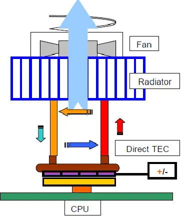
2.3.1 Direct Die Heat sink TEC
9
[image:22.595.217.417.69.269.2]
Figure 2.3: Schematic of CPU cooled by direct die TEC heat sink (H Y Zhang et al., 2010)
2.3.2 Direct Die Liquid Cooling TEC
Alternatively direct die liquid cooling offers a better solution. The heat is dispersed by the thermoelectric cooler into a traditional water cooling system which consisted of a water block, pump and a radiator. However this solution is limited to the available space that is present in the central processing unit die area.
[image:22.595.230.412.505.725.2]10
2.3.3 Chiller TEC
[image:23.595.251.476.344.677.2]Another viable option is to use the chiller method which basically chilled water from TEC are pumped to the water block which directly cool down the central processing unit. Thermoelectric CPU chiller has several implicit advantages. They overcome the limitations of conduction resistance by lowering the temperature of the conductive medium that is adjacent to the central processing unit die, thus increasing the driving temperature differential. Both the hot and the cold side of the modules have access to highly effective heat transfer devices. Additionally they utilize the entire heat transfer surface of the module and distribute the load over several modules, allowing improved coefficient of performance (Davis et al., 2006).However this would lead to a higher cost and power consumption.
11
2.4 Controller
A controller is necessary to control the thermoelectric module from over-cooling the central processor unit than intended. Over-cooling of the central processing unit may cause unwanted condensation to occur without knowledge. Thus a controller is needed. Commonly there are two types of controller that can be used with thermoelectric cooler, namely thermostat and pulse width modulation. However these only provide the means of throttling the power of the thermoelectric module. Therefore a proportional-integral-derivative controller (PID controller) system would be needed to increase the effectiveness of the controller. Apart from that a platform to build the controller would be needed. (Shaojing & Qin, 2010)
2.4.1 Thermostat
A thermostat is simple control systems that act as a switch. It detects the surrounding temperature and switch off or on depending on the needs. For example a set point temperature of 25 Celsius is set, when the surrounding temperature increase beyond the set point temperature it would automatically switch on the power and switch off when the temperature drops below the set point. However the disadvantages of thermostat include huge varying temperature difference since the device is turned off and on at a slow rate simply put it can’t react with the demand fast enough.
2.4.2 Pulse-Width Modulation