A Stand-Alone Hybrid Power System with
Energy Storage
Abu Mohammad Osman Haruni
B.Sc. (BUET), M.ScEng. (University of Tasmania)
A thesis submitted for the fulfilment of the degree of Doctor of
Philosophy
Centre of Renewable Energy and Power Systems (CREPS)
School of Engineering
i Small-scale hybrid stand-alone power systems are becoming popular alternatives in remote and island areas where grid connection is not economically or technically viable. Harnessing the abundant supply of wind and solar energy can play an important role in ensuring an environmentally friendly and clean energy generation for remote and isolated communities. However, renewable energy sources are intermittent in nature, and as a result, power generation from renewable energy sources often may not necessarily match the load demand. Therefore, energy storage is required to ensure reliable power supply.
Hybrid power systems with renewable sources can provide efficiency, reliability and security, while reducing operational costs. However, the main challenge of hybrid power system applications is satisfying the load demand under constraints. Therefore, proper control and coordination of each energy generation unit is vital. It is also important to ensure robustness of the energy management system to avoid system black-outs when power from the renewable energy sources is not adequate to support all loads.
iii The work continued in this thesis has not been published or previously submitted for a degree at this or any other educational institution. To the best of my knowledge, this thesis contains no material previously published or written by another person except where due reference is made.
iv Firstly, I would like to express my deepest and sincerest gratitude to the Almighty, the most compassionate and merciful who guides me in the most appropriate way towards the completion of my research.
I would like to express my sincere gratitude to my primary supervisor Prof. Michael Negnevitsky, University of Tasmania for his valuable advice and help. I would also like to thank all the academic stuff and postgraduate students of the School of Engineering, University of Tasmania, for providing a healthy and helpful academic environment.
v
Refereed journal publications
• Haruni, AMO and Negnevitsky, M, ‘An Artificial Intelligence Approach to Develop a Time-Series Prediction Model of The Arc Furnace Resistance’, Journal of Advanced Computational Intelligence, 14 (6) pp. 722-728.
• Gargoom, AMM and Haruni, AMO and Haque, ME and Negnevitsky, M, ‘Smooth synchronisation and power sharing schemes for high penetration wind diesel hybrid remote area power systems’, Australian Journal of Electrical & Electronics Engineering, 8 (1) pp. 75-84.
• Haruni, AMO and Negnevitsky, M and Haque, ME and Gargoom, AMM, ‘A Novel Operation and Control Strategy for a Stand-Alone Hybrid Renewable Power System’ IEEE transaction of sustainable energy (in press).
Refereed conferences publication
• Haruni, AMO and Negnevitsky, M and Haque, ME and Gargoom, AMM, ‘Control Strategy of a Stand-Alone Variable Speed Wind Turbine with Integrated Energy Storage System Using NPC Converter’, Proc of 2012 IEEE PCS General Meeting, 21-25 July, San Diego, USA, pp. 1-7.
• Haruni, AMO and Negnevitsky, M and Haque, ME and Gargoom, AMM, ‘A Novel Power Management Control Strategy for a Renewable Stand-Alone Power System ’, Proc of 2011 IEEE PCS General Meeting, 24-28 July, Detroit, USA, pp. 1-8.
• Gargoom, AMM and Haruni, AMO and Haque, ME and Negnevitsky, M, ‘Hybrid stand-alone power systems with hydrogen energy storage for isolated communities’, 2010 IEEE PES Transmission and Distribution Conference and Exposition, April 19-22 2010, New Orleans, Louisiana, USA.
• Gargoom, AMM and Haruni, AMO and Haque, ME and Negnevitsky, M, ‘Voltage and frequency stabalizer based on Fuzzy Logic control for three-level NPC converters in stand-alone wind energy systems’, Power and Energy Society General Meeting, 2010 IEEE, July 25-29 2010, Minneapolis, Minnesota, USA. • Gargoom, AMM and Haruni, AMO and Haque, ME and Negnevitsky, M,
‘Voltage and frequency stabilization using PI-like fuzzy controller for the load side converters of the stand alone wind energy systems’, IEEE Power Electronic Society, February 21-25 2010, Palm Springs, California USA, pp. 2132-2137. • Haruni, AMO and Gargoom, AMM and Haque, ME and Negnevitsky, M,
vi USA, pp. 162-169.
• Haruni, AMO and Haque, ME and Gargoom, AMM and Negnevitsky, M, ‘Efficient Control of a Direct Drive IPM Synchronous Generator Based Variable Spwwed Wind Turbine with Energy Storage’, 36th Annual Conference on IEEE Industrial Electronics Society (IECON 2010) , 7-10 Nov 2010, Phoenix AZ, pp. 457-463.
vii
Figures……….. ... xi
Tables……….. ... xvi
Abbrebiation ………vii
Introduction……….. ... 1
Chapter 1: Stand-Alone Hybrid Power System ... 11
1.1 Overview of Hybrid Power System ... 11
1.2 Structure of Hybrid System ... 13
1.2.1 DC-Coupled Systems ... 13
1.2.2 AC-Coupled Systems ... 14
1.2.3 Hybrid-Coupled Systems ... 15
1.3 Wind Energy Conversion System ... 16
1.3.1 DFIG based WECS ... 17
1.3.2 SCIG based WECS ... 18
1.3.3 SG based WECS ... 19
1.3.4 PMSG based WECS ... 20
1.3.5 Multibrid Concept (PMSG with Single Gear-box) ... 21
1.4 Energy Storage System ... 22
1.4.1 Electrochemical Energy Storage ... 24
1.4.2 Mechanical Energy Storage ... 27
1.4.3 Electro-magnetic Storage ... 29
1.4.4 Hydrogen Energy Storage ... 30
1.5 Control Strategy and Energy Management ... 31
1.5.1 Control structure of hybrid power system ... 31
1.6 Challenges for the Fully Renewable Energy based Hybrid Power System Technologies ... 35
Conclusion ... 36
Chapter 2: Wind Energy Conversion System Modelling and Control…………..37
viii
2.2.2 Generalized Model of PMSG ... 44
2.2.3 Modelling of PMSG in d-q Reference Frame ... 46
2.2.4 PMSG Controller Modelling ... 50
2.3 Simulation Results ... 54
Conclusion ... 57
Chapter 3: Energy Storage and Inverter System Control ... 58
3.1 Overview of Energy Storage System... 59
3.2 Battery System Modelling and Control ... 59
3.2.1 Battery System Modelling ... 59
3.2.2 Battery System Control ... 60
3.2.3 Simulation of Battery Controller ... 65
3.3 Hydrogen Storage System Modelling and Control Systems ... 69
3.3.1 Fuel cell Modelling and Control ... 69
3.3.2 Simulation of Fuel Cell Controller ... 77
3.3.3 Electrolyzer Modelling and Control ... 79
3.3.4 Simulation of Electrolyzer Controller ... 82
3.3.5 Compressor and tank model ... 83
3.4 Inverter Control ... 84
3.4.1 Simulation of Load Side Inverter ... 86
Conclusion ... 88
Chapter 4: Diesel Generator Modelling and Control ... 89
4.1 Mathematical Model of Diesel Generator ... 89
4.1.1 Diesel Engine and Governor System Model ... 89
4.1.2 Excitation System Model ... 92
4.1.3 Performance of Diesel Generator Model ... 103
4.2 Modelling of Dual-Fuel Engine with Hydrogen... 105
4.2.1 Experimental Setup ... 105
ix
4.2.5 Case Studies and Model Verification ... 114
4.3 Diesel Generator Synchronization and Power Sharing ... 116
4.3.1 Simulation of Power Sharing of Diesel Generator ... 117
Conclusion ... 119
Chapter 5: System Control and Coordination ... 120
5.1 Configuration of Proposed Hybrid Power System ... 120
5.2 Proposed System Parameters ... 122
5.3 Overall Control, Coordination and Management Scheme... 124
5.3.1 Energy Management and Power Regulation System ... 124
5.4 Performance Evaluation of EMPRS ... 131
5.4.1 Performance of the Local Controllers under Different Wind and Loading Conditions ... 131
5.4.2 Load Management of the System under Low Wind Conditions ... 138
Conclusion ... 141
Chapter 6: Application of the Proposed Stand-Alone Power Supply System: Case Studies ... 143
6.1 Variables Considered for Case Studies ... 143
6.1.1 Wind Profile ... 143
6.1.2 Load Profile ... 145
6.1.3 Battery Management... 147
6.1.4 Hydrogen Storage Management ... 147
6.1.5 Diesel Generator Power Management ... 147
6.2 System Sizing ... 147
6.3 Case Study - Low Wind Conditions During Busy Easter Period ... 148
6.3.1 Case A – System Performance under High Hydrogen and High Battery Storage ve ... 149
x 6.3.4 Case D – System Performance under Medium Hydrogen and Medium
Battery Storage ve ... 155
6.3.5 Case E – System Performance under Low Hydrogen and Low Battery Storage (Emergency operation conditions) ve ... 157
Conclusion ... 159
Conclusions ... 160
xi Fig. 1. Typical fuel consumption and fuel efficiency curve of a diesel generator [5].
... 2
Fig.2. Block diagram of proposed hybrid power system.. ... 9
Fig. 1.1. Schematic diagram dc-coupled hybrid energy system.. ... 14
Fig. 1.2. Schematic diagram ac-coupled hybrid energy system.. ... 15
Fig. 1.3 Schematic diagram of hybrid-coupled hybrid energy system. ... 16
Fig. 1.4. Wind energy conversion system. ... 17
Fig. 1.5. DFIG based WECS. ... 18
Fig. 1.6. SCIG based WECS... 19
Fig. 1.7. SG based WECS. ... 20
Fig. 1.8. PMSG based WECS. ... 21
Fig. 1.9. Multibrid concept. ... 22
Fig. 1.10. Capacity versus discharge time for different energy storage systems. ... 24
Fig. 1.11. Centralized control paradigm. ... 32
Fig. 1.12. Distributed control paradigm.. ... 33
Fig. 1.13. Hybrid centralized and distributed control paradigm. ... 34
Fig. 1.14. Multi-level control paradigm.. ... 34
Fig. 2.1. Configuration of wind energy conversion system.. ... 37
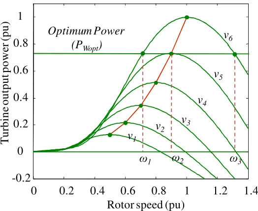
Fig. 2.2. Steady-state power curve of wind turbine.. ... 39
Fig. 2.3. Cp – λ curves for different pitch angle (β). ... 41
Fig. 2.4. Steady-state power curve of wind turbine of differnt wind and rotor speed. 41 Fig. 2.5. Cross sectional view of rotor design of a) SPMSG and b) IPMSG.. ... 43
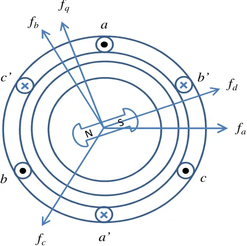
Fig. 2.6. Cross-section view of 3-phase, 2-pole PMSG.. ... 44
Fig. 2.7. d- and q- axes equivalent circuit diagram of PMSG ... 50
Fig. 2.8. Power generation of wind turbine in different rotor and wind speeds. ... 52
Fig. 2.9. The d-axis current vs output electric power.. ... 54
Fig. 2.10. Machine side controller. ... 54
Fig. 2.11. Hypothetical a) wind speed and b) load profile. ... 55
xii
Fig. 3.1. Bidirectional dc-dc converter. ... 60
Fig. 3.2. Bidirectional dc-dc converter operation (time interval t0-t1). ... 61
Fig. 3.3. Bidirectional dc-dc converter operation (time interval t1-t2). ... 62
Fig. 3.4. Bidirectional dc-dc converter operation (time interval t2-t3). ... 63
Fig. 3.5. Bidirectional dc-dc converter operation (time interval t3-t4). ... 63
Fig. 3.6. Control of the bidirectional dc-dc converter.. ... 64
Fig. 3.7. Control of the bidirectional dc-dc converter. ... 65
Fig. 3.8. A battery storage system with control.. ... 66
Fig. 3.9. Load profile.. ... 66
Fig. 3.10. Battery storage system charging and discharging. ... 66
Fig. 3.11. Battery voltage. ... 66
Fig. 3.12. Battery current.. ... 68
Fig. 3.13. SOC of battery storage system. ... 68
Fig. 3.14. dc-link voltage. ... 68
Fig. 3.15. Hydrogen storage system. ... 69
Fig. 3.16. PEM fuel cell. ... 70
Fig. 3.17. Electrical circuit for internal reversible potential . ... 72
Fig. 3.18. Electrical circuit for activation voltage drop. ... 73
Fig. 3.19. Electrical circuit for ohmic voltage drop... 74
Fig. 3.20. Electrical circuit for concentration voltage drop. ... 75
Fig. 3.21. Equivalent circuit of the double-layer charging effect of PEM fuel cells. .. 76
Fig. 3.22. The V-I and power–current characteristics of a PEM fuel cell. ... 77
Fig. 3.23. PEM fuel cell controller. ... 77
Fig. 3.24. Load profile. ... 78
Fig. 3.25. Fuel cell response due to load changes. ... 78
Fig. 3.26. I-U characteristics of an electrolyzer cell at high and low temperature. ... 81
Fig. 3.27. The electrolyzer controller. ... 82
Fig. 3.28. The electrolyzer load consumption. ... 83
xiii
Fig. 3.34. Inverter voltage a) d-axis and b) q-axis component. ... 87
Fig. 3.35 Inverter output power. ... 87
Fig. 3.36. Inverter response at time of 3:00 seconds a) voltage and b) frequency. ... 88
Fig. 4.1. Block diagram of diesel engine and governor system... 92
Fig. 4.2. Block diagram of an exciter system. ... 94
Fig. 4.3. Separately-excited dc exciter. ... 95
Fig. 4.4. Exciter load saturation curve.. ... 96
Fig. 4.5 Block diagram of separately-excited dc exciter. ... 98
Fig. 4.6. Self-excited dc exciter. ... 99
Fig. 4.7. Block diagram of self-excited dc exciter... 99
Fig. 4.8. Block diagram of ac excitation system. ... 100
Fig. 4.9. Block diagram of a rectifier regulation model. ... 101
Fig. 4.10. Block diagram of excitation system stabilizer transformer. ... 102
Fig. 4.11. Block diagram of terminal voltage transducer and load compensator. ... 102
Fig. 4.12. Block diagram of detailed excitation model. ... 103
Fig. 4.13. Diesel generator response: a) Active power, b) reactive power c) frequency and d) voltage response. ... 104
Fig. 4.14. Voltage response due to active and reactive power disturbance at a time of 16 seconds. ... 104
Fig. 4.15. Experimental setup for performance evaluation of the dual-fuel engine.105 Fig. 4.16. Hydrogen performance at 5mg/s hydrogen injection. ... 106
Fig. 4.17. Typical ANFIS architecture. ... 107
Fig. 4.18. The ANFIS model.. ... 112
Fig. 4.19. ‘Generalized bell’ membership function. ... 113
Fig. 4.20. Case Study 1: the injection ratio of diesel and hydrogen is 30. ... 115
Fig. 4.21. Case Study 2: the injection ratio of diesel and hydrogen is 18. ... 115
Fig. 4.22. Case Study 3: the injection ratio of diesel and hydrogen is 25. ... 116
xiv
Fig. 4.25. Voltage during synchronization process (at 5.37 seconds) ... 119
Fig. 4.26. System frequency. ... 119
Fig. 5.1. Hybrid power system. ... 121
Fig. 5.2. The load management algorithm. ... 127
Fig. 5.3 Wind and load profiles. ... 132
Fig. 5.4. Power balance and operation mode sequence of hybrid system. ... 134
Fig. 5.5. Performance of the wind energy conversion system controller. ... 135
Fig. 5.6. System voltage and frequency... 137
Fig. 5.7. Inverter response during load change at 70 seconds where the load decreased from 1.5 kVA to 1.0 kVA: a) voltage and b) current responses. ... 137
Fig. 5.8. Real and reactive power responses... 138
Fig. 5.9. Wind speed profile and generated wind power. ... 139
Fig. 5.10. Load conditions ... 140
Fig. 5.11. Fuel cell, electrolyzer power and hydrogen status. ... 140
Fig. 5.12. Battery power and SOC. ... 141
Fig. 5.13. Power from diesel generator. ... 141
Fig. 6.1. Wind profile from 1- 7 January, 2012... ... 143
Fig. 6.2. Wind profile from 00:00 hour to 24:00 hour on April 14, 2011. ... 144
Fig. 6.3. Wind profile from 00:00 hour to 24:00 hour on December 23, 2011. ... 144
Fig. 6.4. Average hourly load demand during summer period. ... 145
Fig. 6.5. Average hourly load demand during winter period. ... 146
Fig. 6.6. Average hourly load demand during Easter week.... ... 146
Fig. 6.7. Wind and load profile: a) wind and b) load demand. ... 148
Fig. 6.8. Hybrid system operation under high hydrogen and high battery storage.. . 150
Fig. 6.9. Hybrid system operation under high hydrogen and low battery storage... 152
Fig. 6.10. Hybrid system operation under low hydrogen and high battery storage. . 154
xvi
Table 2.1. Parameters of the wind turbine and IPM synchronous generator….…...54
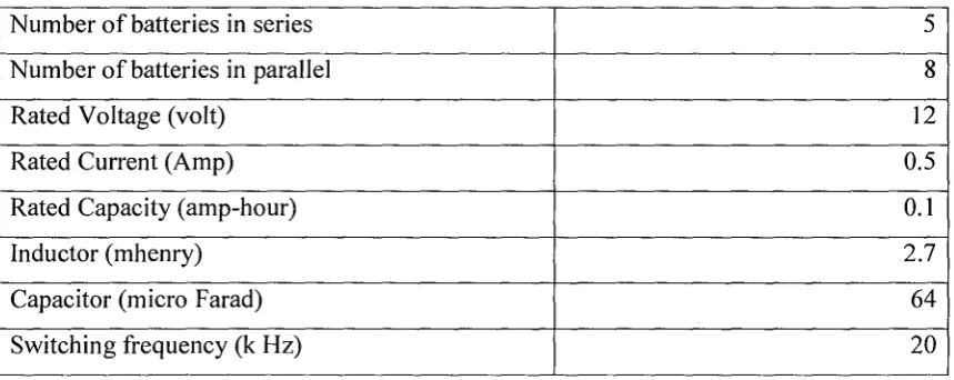
Table 3.1. Parameters of battery system and controller...64
Table 3.2. Parameters of fuel cell and controller...77
Table 4.2. Load demand and power from wind...117
Table 5.1. System parameters...123
xvii AFC Alkaline Fuel Cell
ANFIS Adaptive Neuro-Fuzzy Inference System DFIG Doubly-fed Induction Generator
DMFC Direct Methanol Fuel Cell
EIA Energy Information Administration
EMPRS Energy Management and Power Regulation System EV Electric Vehicle
FSC Full Scale Power Converter HFAC High Frequency Ac- coupled IG Cage Induction
IPM Interior Permanent Magnet
IPMSG Interior Permanent Magnet Synchronous Generator KOH Potassium Hydroxide
MAS Multi-Agent System
MCFC Molten Carbonate Fuel Cell MMF Magneto-motive force NiCad Nickel/ Cadmium NiMH Nickel/ Metal Hydride Pcomp Compressor Power
PEM Proton Exchange Membrane
PEMFC Proton Exchange Membrane Fuel Cell PFAC Power Frequency Ac-coupled
PHEV Plug-in Hybrid Electric Vehicle PID Proportional, integral and derivative PMG Permanent- Magnet Generator
PMSG Permanent- magnet Synchronous Generator PWM Pulse-width Modulation
xviii SOC State of Charge
SOFC Solid Oxide Fuel Cell SOH State of Health
- 1 -
A stand-alone power system is an autonomous power generation system that
supplies electricity without being connected to the grid. Such systems are often located
on islands and in remote parts of the world where grid connection is not technically or
economically viable. The electric power can be generated from diesel, natural gas or
preferably from renewable energy sources such as wind, hydro or solar system.
Diesel generators are popular in remote area power system applications for their
reliability, low installation costs, ease of starting, compact power density and portability
[1], [2]. In stand-alone power system applications, they are generally sized to supply at
least the peak system load. However, diesel generators have some disadvantages as
follows:
• Diesel generators are becoming expensive to run due to increasing fuel cost and
transportation costs. According to the Australian Institute of Petroleum (AIP), the
retail price of the diesel fuel has increased about three times in the last decade [3].
• Diesel generators require a high level of maintenance cost [4], [5].
• Diesel generators are efficient only when running at rated load [5]. A diesel
engine has higher fuel consumption at light loads at constant speed. This is due to
incomplete fuel combustion during light loads [5]. It is usually recommended by
the manufacturers that diesel generators have to run at a minimum load of about
30% to achieve high operating efficiency [6]. The typical fuel consumption and
fuel efficiency curve of a 50 kVA diesel generator is shown in Fig. 1 [5]. From
Fig. 1, it is seen that a typical 50 kVA diesel generator operates at highest
efficiency (about 33%) at the rated load. At 30% of rated load (15 kVA), the
efficiency is as low as 20%. It is also seen that, as the load decreases, the
- 2 -
Fig. 1. Typical fuel consumption and fuel efficiency curve of a diesel generator [5].
• Diesel generators rely on a continuous supply of fuel. As a result, it is important
to ensure security of fuel supply in remote areas.
• Diesel generators pollute the local environment as they emit greenhouse gases
[5], [7] and they also create noise [5].
Renewable energy sources such as hydro, solar, wind, bio-mass, geothermal and
tidal can act as an alternative power sources in stand-alone power system applications, as
they provide clean power for remote communities. In general, there is huge potential for
utilizing renewable energy sources in most remote areas which can provide a clean and
environmentally-friendly power supply to the community. However, the main challenge
of using renewable energy sources for stand-alone power system applications is that the
availability of power has daily and seasonal patterns that may not match the load
demand. Combining renewable energy generation with a stand-by generator or energy
storage device will render the renewable energy sources more reliable and affordable.
This kind of electric power generation system with a main power source from renewable
energy and back up generation or energy storage is known as a ‘hybrid power system’.
The main objective of such systems is to produce as much energy as possible from the
renewable sources while maintaining acceptable power quality and reliability. However,
a renewable energy-based stand-alone power supply system introduces a number of
- 3 -
renewable power, variable loads and low inertial of such systems [8]-[18]. The technical
challenges are listed below:
• Intermittent nature of renewable energy sources – A major challenge for using
renewable energy sources such as wind and solar is that they are variable and
intermittent [8]-[15]. Using such sources in a hybrid power generation system
typically requires extensive backup generation or energy storage capacity in order
to eliminate the effects of their variable and intermittent nature [8]-[15].
• Load fluctuation – Electricity consumption varies over time. These temporal
variations include moment-to-moment fluctuations and hour-to-hour changes
associated with daily, weekly, and seasonal patterns [16]-[18]. As a result, a
renewable energy based hybrid power system has to respond to such load
changes.
• Power quality issues – Perfect power quality means that the voltage is
continuous and sinusoidal, having a constant amplitude and frequency. Power
quality can be expressed in terms of physical characteristics and properties of
electricity. It is most often described in terms of voltage, frequency and
interruptions [19]-[22]. The voltage quality must fulfill stipulated national and
international standards. Within these standards, voltage disturbances are
subdivided into voltage variation, flicker, transients and harmonic distortion.
Voltage variations are caused by the intermittent nature of renewable energy
sources and load fluctuation. Voltage flicker and harmonics may be caused by the
presence of non-linear loads and power electronic converters in the system [23],
[24]. Transients may occur due to the dynamic characteristics of the renewable
energy sources and loads.
• Difference in response time for integrated components – One of the main
challenges of control strategy is to ensure transient stability of different
components of the hybrid power system when they work together. As a
- 4 -
and outputs of renewable sources, energy storage with a fast response is required
to ensure transient stability [25], [26]. Moreover, the hybrid energy storage with
different energy storage devices may respond differently to certain disturbances
[25]-[28]. Therefore, coordinated control needs to be developed to ensure better
transient stability of the stand-alone power system.
• Energy storage strategy and back-up power generation – Energy storage
plays an important role in hybrid stand-alone power system applications, as they
are used for both short-term transient stability and long-term load leveling and
peak shaving applications [25]-[31]. As a result, a proper management of energy
storage is needed to ensure a continuous, reliable and quality power supply.
Back-up power generation is also used in stand-alone power systems. It can be
employed to share power demand, especially during peak load conditions when
power from renewable energy sources and energy reserves in the storage system
are insufficient to satisfy the load demand. Small-scale diesel generators are often
used as the back-up generation.
• Security of supply – Security is defined as the ability of a power system to
withstand sudden disturbances [32], [33]. As a result, sufficient generation
resources must be present to meet projected loads and reserves for contingencies
[32], [33]. Security also implies that the power system will remain intact, even
after outages or equipment failure. As a result, a proper system planning and
operation strategy is vital.
• Demand-side management – Demand-side management (DSM) has been
traditionally seen as a means of reducing peak electricity demands [34], [35].
DSM has various beneficial effects in a stand-alone power system application,
such as mitigating electrical system emergencies, reducing the number of
blackouts and increasing overall system reliability [34]-[35]. Moreover, DSM
also helps to reduce dependency on expensive non-renewable fuel, thus reducing
- 5 -
deferring high-cost investments in generation, transmission and distribution
networks in long-term asset planning. As a result, DSM applied to electricity
systems provides significant economic, reliability and environmental benefits.
• Load growth – Over time, stand-alone power supply systems may experience
increasing load demand as a result of population growth and continuous
economic growth of the community [36]-[38]. As a result, the structure and
overall control strategy has to be flexible enough for the system to increase the
generation rating to cope with increased load demand.
• Economic aspect of hybrid system – In the caseof a stand-alone power system,
the cost of power generation has to be minimized through proper equipment
sizing and load matching [39]-[45]. In the economic analysis, capital and
maintenance costs, and energy cost for different resources have to be accounted
for in order to optimize the hybrid renewable energy-based system.
Meeting the technical and financial challenges associated with renewable
energy-based hybrid power systems requires research in several areas. These are indentified and
categorized as follows:
i) Proper control of renewable energy sources to achieve optimum power
output – It is important to ensure that each energy generation source operates at
its optimum level. Hence, proper control of the renewable energy sources is
required.
ii) Proper co-ordination of each sub-system of the hybrid system –In the hybrid
stand alone power system, proper co-ordination among each subsystem is
essential when they operate together. There, the control system has to coordinate
different sub-systems in order to achieve efficient operation.
iii) Proper selection of energy storage devices – Energy storage devices are an
integral part of the hybrid power system. Energy storage can be classified as
short-term or long-term. Short-term energy storage refers to a storage device
- 6 -
storage is used to improve transient stability of the system in the event of sudden
changes in wind or load conditions [25], [26]. Long-term energy storage is used
for load leveling or peak-shaving purposes [27]-[30]. Proper selection of energy
storage is required to ensure stable, cost-effective and reliable stand-alone
power generation in remote and isolated areas.
iv) Output voltage and frequency regulation – The main challenge of a hybrid
power system is to ensure a power supply with regulated voltage and frequency.
Non-linear, unbalanced load conditions contribute to voltage harmonics and
distortions. Moreover, due to low inertia, the system frequency can be affected
by a sudden load change and the intermittent nature of renewable energy
sources. As a result, power quality issues need to be addressed.
v) Optimum location of energy sources – It is very important to determine the
optimum location of renewable energy sources and storage systems. As the
power output from renewable energy sources depends on geographic location, a
better location can enhance the utilization of renewable energy sources [46],
[47]. In addition, in stand-alone power systems, voltage profile at the
distribution level can fall below operating standards owing to distribution losses.
Energy storage devices installed in critical areas can improve the voltage profile
of the system.
vi) Optimum sizing of the system – Optimum sizing of renewable energy sources
and storage systems need to be determined so as to ensure reliable,
cost-effective power generation of a hybrid power system [39]-[45].
Considering the practical challenges associated with hybrid stand-alone power
supply applications, the following are the main objectives of this thesis:
a.
Components of a hybrid power system for stand-alone operation
Among various renewable energy sources, wind and solar energy are often
- 7 -
tidal energy are more geographically dependent. Favorable conditions for renewable
energy are necessary, as the cost of electricity is heavily dependent on local weather
patterns [46], [47]. In this project wind energy is considered, as wind turbine-based
hybrid power systems offer a cheaper option compared with a solar energy-based hybrid
renewable power supply [47].
Different types of energy storage systems such as pumped hydro, compressed air,
flywheel, thermal, hydrogen, batteries, superconducting magnetic and super-capacitors
are used in various applications for different purposes. Pumped hydro and compressed air
energy storages are low cost options [25]. However, they have lower efficiency.
Moreover, pumped hydro is dependent on the geographical location. Flywheel energy
storage, batteries, superconducting magnetic energy storage and super-capacitors have a
higher energy density and a very fast time response [25], [26]. As a result, they can
support a sudden change of the power demand and provide better transient stability. On
the other hand, fuel cells and electrolyzers have higher power density with slower time
responses [27]- [31]. Therefore, they are more suitable for long-term load leveling
applications. Considering the application of energy storage systems in the wind
turbine-based hybrid power system, a combination of the fuel cell, electrolyzer and battery can
represent the most suitable option. Firstly, excess power from wind can either be stored
in the battery storage system or can be used to generate hydrogen by the electrolyzer.
Secondly, batteries respond very quickly, ensuring better stability of the hybrid system
during transient periods caused by sudden changes of wind and load. Thirdly, this
combination can improve the efficiency of the system by sharing power so as to allow
the operation of a fuel cell in a high efficiency region.
A diesel generator is considered as a back-up for the stand-alone system. In this
project, the diesel generator is used only when the system suffers from severe conditions
such as loss of wind turbine or lack of energy storage.
b.
Control of each energy source
- 8 -
hybrid power system applications, the main objective of the wind turbine control is to
extract optimum power from wind. The energy storage is controlled such as to absorb
excessive power from the wind in high wind conditions and release the necessary power
during low wind conditions. Moreover, the energy storage is also responsible for
ensuring a transient stability of the system under varying wind and load conditions. A
back-up diesel generator is used to provide power only in emergency situations. It is
controlled to run in droop mode (power sharing) or asynchronous mode (stand-alone).
c.
Energy management and power regulation system
In this project, a supervisory controller (energy management and power regulation
system) is developed to ensure optimum energy use and to coordinate local controllers at
each energy generation source. Depending on wind and load conditions, this system
generates reference dynamic operating points to the local controls of individual
sub-systems. It also controls the load scheduling operation during unfavorable wind
conditions with inadequate energy storage to avoid system black-outs.
The project aims to overcome the practical problem associated with renewable
energy based power system application for stand-alone application. The major
contribution of the thesis is listed below:
• Wind turbine control and optimum power extraction from varying wind.
• Energy storage modeling and control.
• Hydrogen storage system modeling and control
• Load side inverter control
• Dual-fuel diesel-hydrogen generator modeling and control.
• Energy management and power regulation system.
The overall system diagram is shown in Fig. 2.
The thesis organized as follows:
Chapter 1 presents a literature review of a renewable energy-based hybrid
- 9 -
AC -DC
DC-DC
DC-DC
Supervisory Controller
Optimum power point tracking
Battery power control
DC
-AC Load 1
Load 2
Load 3 C
B Synchronizer
Power flow control Voltage and frequency control
DC-DC Wind
Turbine
Electrolyzer
Fuel Cell
Battery Storage Hydrogen
Storage
Diesel Generator
Electrolyzer power control
Fuel cell power control
Control Power flow
Fig.2. Block diagram of proposed hybrid power system.
their structure, different power generation sources, energy storages and associated control
and coordination techniques of hybrid power systems.
Chapter 2 presents the wind turbine modelling and control. This chapter discusses a
permanent magnet based variable speed wind turbine. The optimum power extraction
technique is also presented.
Chapter 3 presents the energy storage system and load side inverter modelling and
controls. It discusses about the modelling and control aspects of the battery storage
system, fuel cell and electrolyzer. Moreover, this chapter focuses on the interaction of
each energy storage system. This chapter also demonstrates the output voltage and
- 10 -
Chapter 4 presents the details modelling and control of a diesel generator. This
chapter also discusses about the ‘black-box’ modelling of a dual fuel diesel-hydrogen
generator. Power sharing techniques of diesel generator with other power generation
sources are also included.
Chapter 5 presents the supervisory controller modelling. It discusses about the
overall coordination of a hybrid system. A load shedding algorithm is proposed, which
ensures continuous system operation, thus avoiding system black-outs.
Chapter 6 presents a case study of proposed hybrid system. A number of case
studies are presented in different wind and loading conditions to justify the application of
the proposed system for stand-alone operation.
- 11 -
Stand-Alone Hybrid Power System
This chapter presents an overview relevant to the scope of the proposed research
project, comprised of different sections. Section 1.1 provides an overview of a renewable
energy based hybrid power system. Section 1.2 presents different structures of the hybrid
power supply system. Section 1.3 provides in-depth literature of a wind energy
conversion system. Section 1.4 presents a detailed study of an energy storage system.
Section 1.5 provides different control and co-ordination techniques for a stand-alone
power system. Section 1.6 provides the challenges, issues and future vision of fully
renewable energy based hybrid power system. Finally, some remarks are presented to
conclude the chapter.
1.1 Overview of Hybrid Power System
With the rapid growth and challenges of power generation, distribution, and
usages, renewable energy technologies can play an important role in future power supply
due to increased awareness of environmental pollution. In the case of power supply
system to remote and isolated communities, a renewable energy based stand-alone power
system can be a particularly attractive cost-effective solution, as grid extension is often
impractical due to economic and technical constraints.
Diesel generators are most commonly used as a stand-alone power supply system
application to remote and isolated communities for their reliability, cheap installation,
ease of starting, compact power density and portability [48], [49]. However, rising fuel
prices make them very expensive to run. Moreover, they cause significant environmental
pollutions. In most remote and isolated areas, renewable energy sources such as wind and
solar are available, which can provide clean cost-effective power. However, due to the
- 12 -
energy sources along with energy storage can improve reliability and ensure a continuous
and cost-effective power supply.
Different generation sources may operate in tandem to achieve higher energy
efficiency and improve system performance. As an example, wind and solar power can
complement each other on daily basis. Integration of battery or super-capacitor storage
systems can improve transient stability of a fuel cell and wind turbine based hybrid
power system in the event of wind and load changes [50]-[52].
In renewable energy-based hybrid power system applications, energy storage is
considered as an integral part of the system [53]-[67]. Energy storage can improve
transient stability of the system when wind and load variation occurs [53]-[55]. Most
importantly, they are used for load leveling and peak shaving applications [56], [57].
However, proper technology selection, operation and control strategies, structure of the
hybrid power system, and generation unit sizing are also vital to construct a robust
renewable energy based hybrid power supply system [62]-[67].
A case study reported in [46] describes a cost-effective power supply solution in a
remote area in Tunisia. The climate of Tunisia, located in North Africa, well-suited to the
use of solar energy. There are many small, remote locations in Tunisia which rely on
diesel generators for electric power, as grid extension is not economically feasible. The
cost of running these generators can be quite expensive when accounting for the
transportation costs and efficiency of diesel generators during off-peak periods. As a
result, a hybrid solar power with battery storage-based power system was considered for
continuous power supply in this area. It has been shown that the power generation cost of
hybrid a solar and battery storage system is $240.65 per MWh, whereas a diesel
generator based power supply system costs about $289.1 per MWh. In favorable wind
conditions, wind turbine-based hybrid power systems can offer a cheaper solution
- 13 -
1.2 Structure of Hybrid System
A well-defined framework of a hybrid system is vital, as various energy sources
may have different operating characteristics. In an optimal framework, the renewable
energy sources, energy storage, and loads are integrated and capable of operating
autonomously as a unit [68]. A robust system should also have a “plug-and-play”
capability which renders the system capable of integrating any number of devices
without system re-configuration [68], [69].
There are various ways to integrate different energy sources and storage to form a
hybrid power system. Among them, dc-coupled, ac-coupled and hybrid-coupled are the
most popular options [70]-[74], which outlined as below:
1.2.1 DC-Coupled Systems
In a dc-coupled system, all renewable energy sources are connected to a dc bus
either directly or through appropriate power electronic converters. A block diagram of
the system is shown in Fig. 1.1. This system can be connected to the dc loads through
appropriate dc-dc converter, ac loads through a dc-ac converter or utility grid through a
bi-directional dc-ac converter. The system is flexible and can be connected to an ac load
of 50/60 Hz frequency. The dc-coupling scheme is very simple and is not required to be
synchronous with the ac system. However, a dc-coupled system suffers from various
weaknesses. For example, if the system converter connecting the utility grid with the bus
is out of service, the whole system will not be able to supply ac power. To rectify this,
several inverters can be connected in parallel. As such, synchronization of output ac
- 14 -
AC sources
DC sources
Energy Storage
AC DC
DC bus
AC bus
DC DC
PE Circuit
DC Loads
DC AC
50/60 Hz Grid
AC Loads
Fig. 1.1. Schematic diagram dc-coupled hybrid energy system.
1.2.2 AC-Coupled Systems
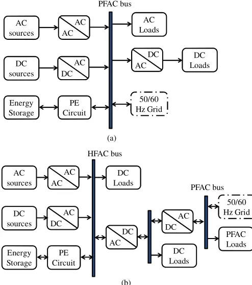
An coupled system can be divided into two categories: power frequency
ac-coupled (PFAC), and high frequency ac-ac-coupled (HFAC) systems. The PFAC ac-coupled
system is shown in Fig. 1.2 (a), where the different energy sources are integrated through
their own power electronic interfacing circuits to a power frequency ac bus. In this
arrangement, coupling inductors are required between the power electronic interfacing
circuits and power frequency ac bus to achieve the desired power flow management.
The HFAC system is shown in Fig. 1.2 (b), where different energy sources are
coupled to a HFAC bus in which HFAC loads are located. This application is mainly
used for HFAC loads (e.g., 400 hz) such as airplanes, vessels, submarines and space
stations.
In both PFAC and HFAC systems, dc power can be obtained through an ac-dc
converter. The HFAC may also include a PFAC bus and utility grid through an
- 15 -
AC sources
DC sources
Energy Storage
AC AC
PFAC bus
DC AC
PE Circuit
AC Loads
AC DC
50/60 Hz Grid
DC Loads
DC Loads
AC DC
50/60 Hz Grid
DC Loads AC
sources
DC sources
Energy Storage
AC AC
HFAC bus
PFAC bus (a)
(b) DC
AC
PE Circuit
DC AC
[image:34.612.180.427.105.384.2]PFAC Loads
Fig. 1.2. Schematic diagram ac-coupled hybrid energy system.
1.2.3 Hybrid-Coupled Systems
In hybrid-coupled system as shown in Fig. 1.3, various DG sources are connected
to the dc or ac buses of the hybrid system. In this application, some energy sources can
be implemented directly without the use of a power electronic interfacing system. As a
result, the system can operate with higher efficiency and reduced cost. However, control
and energy management can be more complicated than with dc-coupled and ac-coupled
- 16 -
DC Loads
DC AC
50/60 Hz Grid AC
sources
DC sources
Energy Storage
AC DC
DC bus PFAC bus
DC DC
PE Circuit
AC Loads PAFC
Energy Storage
Fig. 1.3. Schematic diagram of hybrid-coupled hybrid energy system.
Different coupling schemes have their own appropriate applications. If the major
generation sources generate dc power and there is a substantial dc load in the system, a
dc-coupling system is preferable. On the other hand, if the main power systems are ac
with substantial ac loads, an ac-coupled system is preferred. If the major power
generation system is a combination of ac and dc power, then hybrid coupled system is the
best.
1.3 Wind Energy Conversion System
In the last decade, wind power generation systems have experienced tremendous
growth and been recognized as an alternative environmentally-friendly and cost-effective
means of power generation. The major components of a typical wind energy conversion
system (WECS) include a wind turbine, generator and control systems. Fig. 1.4 shows a
WECS. The generators conventionally used in WECSs are the doubly-fed induction
generator (DFIG), cage induction generator (IG), and synchronous generators (SG). The
power electronics correspond to a back-to-back converter. The WECS can be connected
- 17 -
AC DC
LC filter
Local Load
Utility
Micro-grid Wind Turbine
Gear-box (Optional)
Convertor (optional) AC
DC Generator
Transformer
Fig. 1.4. Wind energy conversion system.
1.3.1 DFIG- based WECS
The DFIG is widely used for variable-speed generation and is one of the most
important generators for wind-energy applications [76]-[81]. The DFIG-based WECS is
shown in Fig. 1.5. Nowadays, the DFIG-based wind turbine accounts for about 50% of
wind energy market share. For a typical DFIG, a back-to-back power converter is
connected to the rotor for a restricted speed range of operation, typically 30% of its rated
value [78], [79]. In DFIG-based WECS, slip rings connect the machine-side converter to
the rotor, and gearboxes are also required, since a multi-pole low-speed DFIG is not
technically feasible [57].
DFIG-based WECS speed can be regulated for desired electrical torque via the
rotor-side converter. Speed regulation is mainly used to optimize power extraction from
the wind. The possibility of controlling the active and reactive power gives this system
rolling capacity on the grid [82]-[84].
A DFIG-based WECS can contribute to the short-circuit power because the stator
is directly coupled to the grid. Therefore, during a grid fault, relatively high currents may
be produced in the DFIG stator windings. However, direct connection between stator and
grid may limit the capacity of this generator to remain connected to the system during a
fault period. To improve the fault handling capacity, a crowbar is usually adopted to limit
- 18 -
converter is used. The three-phase rotor winding is short-circuited via the closed crowbar
switch which transfers the DFIG in a standard IG. During the switching operation, the
high currents produced may cause sudden torque loads on the drive train.
Most major wind turbine producers manufacture WECSs based on DFIGs.
However, difficulties in complying with grid fault ride-through requirements may limit
its use in the future [85], [86].
AC DC
LC filter
Local Load
Utility
Micro-grid Wind
Turbine
Gear-box
Convertor AC
DC DFIG
Real and Reactive Power Control Maximum Power
Extraction Grid
Fault-Ride-Through V/I
Vdc
ω
Xfilter
V/I Supervisory Command PWM
PWM
Fig. 1.5. DFIG-based WECS.
1.3.2 SCIG-based WECS
The squirrel-cage IG (SCIG) shown in Fig. 1.6, is a very popular machine due to its
mechanical simplicity and robust construction [76]. Unlike the DFIG, no brushes are
required for the machine’s operation. Minimal maintenance is necessary, apart from
bearing lubrication. The SCIG was widely used in fixed-speed WECS [76] (first Danish
wind turbines), and it is still used for variable-speed wind-energy generation. The IG
with a frequency converter is completely decoupled from the grid; hence this system has
- 19 -
The main drawbacks of the SCIG reside in the fact that two full power converters
are required for operation and a multi-pole direct-drive operation is not technically
feasible [76]. Therefore, SCIGs do not have the advantage of variable-speed operation
using reduced-size power converters (as in the DFIG). SCIGs cannot be used in
direct-driven WECS [as in permanent-magnet generators (PMGs)]. Hence, the number of
WECS producers manufacturing topologies based on SCIGs is relatively low.
AC DC
LC filter
Local Load
Utility
Micro-grid
Wind Turbine
Gear-box
Convertor
AC DC SCIG
Real and Reactive Power Control
Maximum Power Extraction
Grid Fault-Ride-Through V/I
Vdc
ω
Xfilter
V/I
Supervisory Command PWM
PWM
Fig. 1.6. SCIG-based WECS.
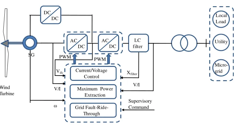
1.3.3 SG-based WECS
In SG based WECS shown in Fig. 1.7, an excitation is provided via rotor windings.
Hence, a full-scale power converters (FSCs) are needed, and a reduced scale converter
for the excitation is required for synchronous machines.
The cost, weight and size of the SG based wind turbine are higher than its DFIG
counterpart. The reliability of direct drive SG is very high due to the absence of a
gearbox, the slipping ring, and brushes. As a result, they are more suitable for
applications where the logistics could be a problematic and robustness is of paramount
importance; e.g., offshore wind parks. Moreover, they can have a better ride-through
- 20 -
AC DC
LC filter
Local Load
Utility
Micro-grid Wind
Turbine
AC DC SG
Current/Voltage Control Maximum Power
Extraction Grid
Fault-Ride-Through V/I
Vdc
ω
Xfilter V/I Supervisory Command PWM
PWM DC
[image:39.612.97.475.92.293.2]DC
Fig. 1.7. SG-based WECS.
1.3.4 PMSG-based WECS
PMSGs are considered to be one of the most promising technologies for wind
energy systems [76], [87]. In PMSG-based WECS, full-scale power converters (FSCs)
are needed.
The direct-drive permanent-magnet SG (PMSG) shown in Fig. 1.8, is considered to
be the most efficient, as power losses are about 65% of a typical DFIG-based WECS
[88]. However, the cost, weight and size of the PMSG-based wind turbine is higher than
its DFIG counterpart. The reliability of direct drive PMSG is very high due to the
absence of a gearbox, slipping rings, and brushes. As a result, they are more suitable for
applications where the logistics could be a problematic and robustness is of paramount
importance; e.g., offshore wind parks. Moreover, they can have a better ride-through
capability.
Multi-pole PMSGs with full-power back-to-back converters appear likely to be the
configuration adopted by most large wind-turbine manufacturers in the near future,
replacing the doubly-fed generator as the main generator in the wind-energy market. An
- 21 -
gearbox is eliminated from the WECS [89]. For offshore applications, increased
reliability and the elimination of possible oil spills from the gearbox is another
advantage.
AC DC
LC filter
Local Load
Utility
Micro-grid
Wind Turbine
AC DC PMSG
Current/Voltage Control
Maximum Power Extraction
Grid Fault-Ride-Through V/I
Vdc
ω
Xfilter
V/I
Supervisory Command PWM
PWM
Fig. 1.8. PMSG-based WECS.
1.3.5 Multibrid Concept (PMSG with Single Gearbox)
With the increase in WECS rated power, the direct-drive operation of generators
may require electrical machines of considerable size, weight and cost. In this case, a
topology introduced by the German company Multibrid is shown in Fig. 1.9. The
Multibrid concept developed a WECS comprised of a medium-speed PMSG and a
single-stage gearbox with a gear ratio of 6–10 [90], [91]. This allows weight and size
reduction of the generators combined with gearbox technology which is lighter, more
- 22 -
Wind Turbine
Gear-box
AC DC
LC filter
Local Load
Utility
Micro-grid AC
DC PMSG
Current/Voltage Control Maximum Power
Extraction Grid
Fault-Ride-Through V/I
Vdc
ω
Xfilter
V/I Supervisory Command PWM
PWM
Fig. 1.9. Multibrid concept.
Among different types of WECS, the DFIG based WECS is very popular as the
lightest, low cost solution with standard components. However, it has a low energy yield
due to high losses in the gearbox. Since it is mainly built from standard components
consisting of copper and iron, major improvements in performance or cost reduction
cannot be expected.
The direct drive PMG generator seems far more feasible, since the active material
weight of the generator for the same air-gap diameter is nearly halved, while the energy
yield is several percent higher. While having the highest energy yield, it is more
expensive than the generator systems with a gearbox. Further improvements can be
expected since the cost of the permanent magnets and the power electronics is
decreasing.
1.4 Energy Storage System
Energy storage systems are an integral part of a hybrid renewable stand-alone
power system, which is critical for ensuring a high level of power quality, reliability and
security. An ideal storage system would offer fast access to power as required, provide
- 23 -
However, an ideal storage system is not currently available. As a result, it is important to
select the appropriate storage technology for the application of renewable energy based
hybrid power systems. The preliminary applications of energy storage systems for a
stand-alone hybrid renewable energy based power system are as follows:
• Renewable matching and power smoothing
Renewable energy sources are intermittent in nature. As a result, power
generation frequently fails to match the load profile or demand cycle. Energy storage can
be used to match the output of renewable sources to any load profile.
• Load leveling application
In load leveling application, bulk energy is stored during peak wind conditions
and then discharged during low or no wind conditions. As a result, proper management
of energy storage can ensure continuous system operation.
• Power quality
Utility power sometimes suffers disturbances such as momentary voltage sags or
even outages. Along with harmonic distortions, and other imperfections can affect
sensitive equipment requiring high quality power. Energy storage systems can be used to
provide reliable, high quality power to sensitive loads.
Based on the application, the energy storage can be classified as long-term and
short-term. Capacity-oriented energy storage technologies such as pumped hydroelectric
systems, compressed air energy storage and hydrogen storage do not generally have a
fast response time and are used for long-term energy storage. On the other hand, storage
devices with a fast response time such as batteries, fly-wheels, super-capacitors and
super-conducting magnetic energy storage (SMES) are used for responding to short time
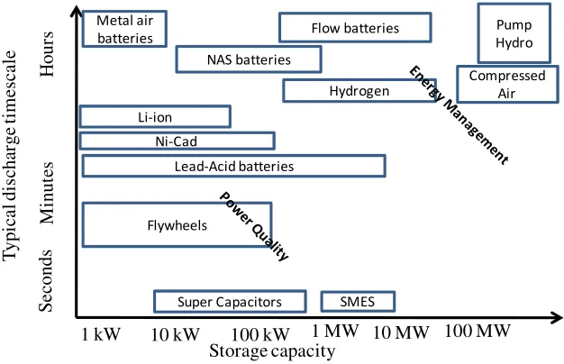
- 24 -
1.10 shows the typical storage capacity versus discharge time for different energy storage
systems. S ec o n d s M in u te s H o u rs
1 kW 10 kW 100 kW 1 MW 10 MW 100 MW
T y p ic al d is ch ar g e ti m es ca le Storage capacity Metal air
batteries Flow batteries
Pump Hydro Compressed Air NAS batteries Hydrogen Li-ion Ni-Cad Lead-Acid batteries Flywheels
Super Capacitors SMES
[image:43.612.125.438.153.355.2]
Fig. 1.10. Capacity versus discharge time for different energy storage systems.
Energy storage can be electrochemical, mechanical, electromagnetic, thermal or
hydrogen-based.. Electrochemical energy storage includes lead-acid, lithium-ion, flow
and sodium-sulfur batteries. Mechanical energy storage includes pumped hydroelectric,
compressed air energy and fly-wheel. Electro-magnetic storage systems such as
superconducting magnetic energy storage (SMES) and thermal energy storage can
include solar thermal and thermal storage for heating, ventilation and air conditioning.
Hydrogen storage includes electrolyzer and fuel cells.
1.4.1 Electrochemical Energy Storage
Batteries used to store and supply power to renewable energy based power systems
must be reliable, durable and safe. Several promising battery technologies exists for grid
connected or stand alone based renewable energy system applications including
- 25 - • Lead-acid batteries
Lead-acid batteries are mature and proven technology in a number of applications
including frequency regulation, bulk energy storage for variable energy renewable
energy integration and distributed energy storage systems. These batteries are a viable
option owing to relatively low cost, ease of manufacture, rapid electrochemical reaction
kinetics and good life cycle under controlled conditions [92]. Conventional lead acid
batteries typically achieve 20-30 Wh/kg, with a power density of 4 kW/kg [92].
Maintenance free valve-regulated lead-acid (VRLA) batteries, also known as sealed lead
acid batteries, have largely replaced conventional high maintenance flooded cell batteries
in a variety of applications such as automotive, marine, telecommunications and
uninterruptible power supply system. However, for large storage system applications for
grid support, flooded lead-acid technology is still considered as the best alternative [93].
The lifetime of lead-acid batteries varies significantly depending on the application,
discharge rate and number of deep discharge cycles. In the case of a renewable energy
based power system, traditional lead-acid batteries may experience a short life-cycle and
require significant maintenance due to uncontrollable charging and discharging operating
cycles.
• Nickel-based batteries
Nickel-based batteries can be in the form of Nickel/Cadmium (NiCad) and Nickel
Metal Hydride (NiMH) systems. The main application for NiCad batteries is portable
electronics. Compared with the lead-acid battery, NiCad batteries have a longer life,
higher energy density and lower maintenance. NiMH batteries are a feasible alternative
to NiCad batteries owing to better performance and environmental benefits. Compared
with lead-acid and NiCad batteries, NiMH does not contain toxic substance such as
cadmium or lead. The energy density of NiCad cells is 25 - 30% higher than NiCad cells
- 26 - • Lithium-ion batteries
Lithium is an attractive material for battery technology as it has a higher reduction
potential and lighter weight [93]. Rechargeable Li-ion batteries are commonly found in
consumer electronic products, comprising most of the global production volume of 10 to
12 Giga-watt hours per year [93]. These batteries are widely used in plug-in hybrid
electric vehicles (PHEV) and electric vehicles (EV).
Compared to the long history of lead-acid batteries, Li-ion technology is relatively
new. It is expected that the EV and energy storage market will substantially benefited
from advancements in Li-ion battery technology. The high energy density and relatively
low weight results in a viable choice for electric vehicles and other applications where
space and weight are important. Given their long cycle life and compactness, higher
roundtrip energy of 85 – 90% [95], Li-ion battery manufacturers may be used for various
utility grid-support applications including distributed energy storage systems at
community scale, commercial end-user energy management, home back-up energy
management systems, frequency regulation and wind and photovoltaic power smoothing
applications.
• Flow batteries
A flow battery is a rechargeable battery where electrolyte containing one or more
dissolved electro-active species flow through an electrochemical cell which converts
chemical energy to electricity [93]. Vanadium redox battery technology is one of the
most mature flow battery systems available, with an expected life of about 15 years [93].
However, the physical scale of this battery is mainly due to the large volume of
electrolyte required when sized for utility-scale projects.
Flow batteries are an attractive energy storage option for the grid because of their
ability to store a large amount of energy with a potentially longer life-cycle. However,
- 27 -
active species in the anode and cathode electrolytes may lead to efficiency loss and
contamination.
• Sodium sulfur batteries
The sodium sulfur battery possesses high energy and power density and electrical
efficiency. Its long life results in an excellent choice for electric power system
applications [93]. Sulfur is used as an active material at the positive electrode and sodium
is used at the negative electrodes. Electrodes are separated by sodium-ion-conductive
ceramic solid electrolyte. High temperature maintains the electrode active materials in a
liquid state while the electrode is solid. This reduces resistance and enables efficient
battery performance averaged over lifetime discharge [93].
• Super-capacitors
Super-capacitors are devices that store electrical energy as charge separation in
porous electrodes with large surface areas. Some key benefits of ultra capacitors include
highest capacitance density of any capacitor technology, low cost per farad, reliable, long
life, high cycle-life, maintenance-free operation, environmentally safe, a wide range of
operating temperatures high power density and good energy density [92].
Of these features, the greater power and energy densities bridge the gap between
standard batteries and traditional capacitors for high-power, short-duration energy
storage. As a result, they are widely used in utility applications for transmission line
stability, spinning reserve, frequency control, voltage regulation, power quality and
uninterruptible power supply applications [74].
1.4.2 Mechanical Energy Storage
Pumped hydro, compressed air energy storage and flywheels can be classified as
- 28 - • Pumped hydro
Pumped hydro electric storage is the oldest, most widespread commercially
available energy storage technology. Such schemes consist of two large reservoirs at
different levels with a store of water. Off-peak electricity is used to pump water up to the
top reservoir, which can then be discharged as required, typically to a lower reservoir at
the other end of a height differential. This flow of water drives turbines in the same way
as hydro-electric dams.
The technology can provide reliable power at short notice, typically within one
minute, with efficiency in the range of 70-85% [95]. Overall the technology is one of the
most mature on the market and further technological advances are considered unlikely.
Pumped hydro is the main form of energy storage globally and has been used since the
1890s. There is approximately 90GW of pumped storage in operation worldwide,
accounting for 3% of global generation capacity [96]. A limiting factor is the large
capital costs involved in construction (although cost is highly dependent on local
topography and other factors). For example, the 1080 MW Goldisthal plant in Germany
cost $700 million in 2002 [96].
• Fly wheel
Flywheels represent a mechanical form of energy storage in which the kinetic
energy of a fast-spinning cylinder contains stored energy. Recent technological advances
of fly-wheel have improved the efficiency of the traditional flywheel [93]. Modern
flywheel systems are typically comprised of a massive rotating cylinder, supported on a
stator by magnetically levitated bearings that eliminate wear and extend system life. To
increase efficiency, the flywheel is operated in a low pressure environment to reduce air
friction. This energy storage system draws electricity from a primary source to spin the
high density cylinder at speeds greater than 20,000 rpm. When the primary source loses
its power, the motor acts as a generator. As the flywheel continues to rotate, this
- 29 -
Flywheels have a high energy density of 50 – 100 Wh/kg and an efficiency of
around 90%, depending on the flywheel’s speed range [96]. With no chemical
management or disposal to consider, flywheels have certain environmental advantages
over battery systems.
• Compressed air energy storage
In compressed air energy storage system (CAES), air is compressed into
underground mines or caverns by using off-peak electricity, which improves the
efficiency of the gas turbine [93]. When required, the compressed air is utilized in
conjunction with a gas turbine to generate electricity, resulting in gas consumption
reductions of 60% relative to the same amount of electricity generation directly from gas
[93]. Compressed air energy storage can be integrated with a wind farm in order to store
additional power during high wind conditions. The energy efficiency of CAES is around
80%. The availability or generation of large underground storage spaces can have
possible environmental impacts, and constraint on this technology is constrained by the
absence of suitable locations for underground air storage.
1.4.3 Electro-magnetic storage
• Superconducting magnetic energy storage
Superconducting magnetic energy storage (SMES) can store electrical energy in a
magnetic field within a cooled conducting coil. The coil is cooled beyond its
super-conducting temperature (-269oC), where the resistance of the material is very low. This
limited electrical resistance allows SMES to achieve high efficiency of up to 97%. Since
the SMES can release immediate energy, It is useful where customers require an
extremely high quality power output. As the SMES is currently undergoing research and