University of Southern Queensland
Faculty of Engineering and Surveying
The Design and Construction of an
Exercise Device for Use in Physiotherapy of
the Arm
A Dissertation submitted by
Jake Salomon
In fulfilment of the requirements of
Courses ENG4111 and ENG4112 Research Project
Towards the degree of
A
BSTRACT
This project set out to develop a low cost, in-home robotic rehabilitation device for
stroke patients suffering arm paralysis. The forecast increase in stroke caused by
obesity and the aging population will place more strain on social services and
resources. There is a requirement to move away from traditional therapy with the
alternative being computer-based rehabilitation devices that allow patients to
exercise in the comfort and safety of their homes.
This project has researched stroke and its debilitating effects along with
rehabilitation goals and techniques. This research revealed the potential to introduce
a low cost robotic rehabilitation device. The project conceptualised, designed and
manufactured a device that simulates most of the natural range of motion of the arm.
The device is linked to a computer and offers an on-screen representation of the
patient’s movements.
Testing has shown that the device has great potential in the medical world and will
offer stroke patients a more accessible rehabilitation technique. With some
refinement of the design and improved software, the device will be ready for clinical
testing. All of this work aims to help the patient return to normal everyday living
C
ERTIFICATION
I certify that the ideas, designs and experimental work, results, analyses and
conclusions set out in this dissertation are entirely my own effort, except where
otherwise indicated and acknowledged.
I further certify that the work is original and has not been previously submitted for
assessment in any other course or institution, except where specifically stated.
Jake Salomon
Student Number: 0050072223
____________________________
Signature
____________________________
A
CKNOWLEDGEMENTS
I would like to thank my project supervisor, Dr Selvan Pather for his valued help and
reliable guidance over the last year, and the USQ workshop for constructing this
device.
To my friends and family, thankyou for your support and patience throughout my
T
ABLE OF
C
ONTENTS
Abstract ... i
Limitations of Use ... ii
Certification ... iii
Acknowledgements ... iv
Table of Contents ... v
List of Figures ... xi
List of Tables ... xv
Glossary ... xvi
Chapter 1 Introduction ... 1
1.1 Introduction ... 1
1.2 Motivation ... 1
1.3 Project Objectives ... 2
1.4 Methodology ... 2
1.5 Overview of Dissertation ... 3
1.6 Conclusion ... 4
Chapter 2 Background ... 5
2.1 Introduction ... 5
2.2 Stroke ... 5
2.3 Stroke Statistics ... 5
2.4 Types of Stroke ... 6
2.5 Effects of Stroke ... 7
2.6 Rehabilitation ... 9
2.6.1 Reason for Rehabilitation ... 9
2.6.2 Rehabilitation Goals ... 9
2.6.4 Muscle Development ... 11
2.6.5 Current Rehabilitation Techniques ... 11
2.6.5.1 Rehabilitation by Physical Therapy ... 11
2.6.5.2 Constraint Induced Movement Therapy ... 12
2.6.5.3 Issues with Current Rehabilitation Techniques ... 13
2.6.6 Measuring Rehabilitation Progress ... 14
2.7 Robotic Assisted Rehabilitation ... 14
2.7.1 Advantages ... 14
2.7.2 Limitations ... 15
2.7.3 Recently Developed Devices ... 15
2.7.3.1 T-WREX ... 16
2.7.3.2 HOWARD ... 16
2.7.3.3 MIT-Manus ... 17
2.8 Interview with Jude Wilson – Physiotherapist ... 18
2.9 Conclusion ... 19
Chapter 3 Design Constraints and Requirements ... 20
3.1 Introduction ... 20
3.2 Requirements of a Robotic Rehabilitation Device ... 20
3.2.1 Size, Form & Portability ... 20
3.2.2 Movement ... 21
3.2.3 Cost ... 21
3.2.4 Position Monitoring ... 21
3.4 Movement of the Human Arm ... 23
3.4.1 Basic Anatomy ... 23
3.4.2 Degrees of Freedom ... 25
3.4.3 Range of Motion ... 28
3.5 Conclusion ... 29
Chapter 4 Concept Development ... 30
4.1 Introduction ... 30
4.2 Presently Available Hand Control Devices ... 30
4.2.1 Joystick ... 30
4.2.2 Stewart Platform (Hexapod) ... 32
4.2.3 Haptic Devices ... 34
4.2.4 Conclusion ... 35
4.3 Previous Work at USQ ... 36
4.4 Concepts of Structure ... 37
4.4.1 Concept 1 – Cables and Pulleys ... 37
4.4.2 Concept 2 – Lever Arms ... 38
4.4.3 Concept 3 – Linear Shafts ... 40
4.5 Concepts of Position Monitoring ... 41
4.5.1 Concept 1 – Potentiometers ... 41
4.5.2 Concept 2 – Linear Encoders ... 43
4.6 Conclusion ... 44
Chapter 5 Final Design and Manufacture of Prototype ... 45
5.1 Introduction ... 45
5.2 Choosing a Design ... 45
5.3 Design of Structure ... 46
5.3.1 Sizing ... 46
5.3.3 General Structure ... 55
5.3.4 Shaft Selection ... 55
5.3.4.1 Stress and Deflection ... 56
5.3.4.2 Density and mass ... 63
5.3.4.3 Surface Hardness ... 64
5.3.4.4 Availability ... 65
5.3.4.5 Corrosion Resistance ... 65
5.3.4.6 Final selection ... 65
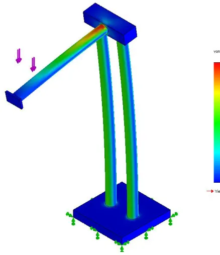
5.3.4.7 Finite Element Analysis ... 66
5.3.5 Bearing Selection ... 67
5.3.6 Detailed Design ... 68
5.4 Design of Position Monitoring system ... 74
5.4.1 Choosing a System ... 74
5.4.2 Gear and Belt Selection ... 76
5.4.3 Detailed Design ... 77
5.5 Weight Block (Counterweight) ... 82
5.6 Design of Electronics ... 83
5.6.1 Microcontroller and Development Board ... 83
5.6.2 Potentiometers ... 86
5.6.3 Circuitry ... 86
5.7 Conclusion ... 88
Chapter 6 Development of Software and Interface ... 90
Chapter 7 Evaluation and Testing of Design ... 97
7.1 Introduction ... 97
7.2 Structure ... 97
7.2.1 Problem with linear bearing joints ... 97
7.2.2 Horizontal Shaft Rotation ... 98
7.2.3 Top Bar Bending ... 99
7.2.4 Changes to Wrist Device Mounting ... 100
7.3 Range of Motion ... 102
7.4 Position Monitoring System ... 109
7.4.1 Grub Screw holes Stripped... 109
7.4.2 Wasted Range of Motion ... 110
7.4.3 Testing ... 110
7.5 Software and Interface ... 113
7.6 Effectiveness of Device ... 113
7.7 Conclusion ... 113
Chapter 8 Conclusions and Future Work ... 114
8.1 Introduction ... 114
8.2 Achievements ... 115
8.3 Future Work ... 116
8.3.1 Structure ... 116
8.3.2 Wrist Device... 117
8.3.3 Force Feedback ... 117
8.3.4 Electronics and Software... 118
8.4 Conclusion ... 119
List of References ... 120
Appendix A Project Specification ... 124
B1 Microcontroller Code ... 125
B2 Computer Code – Main Application ... 131
B3 Computer Code - RS232COM ... 137
L
IST OF
F
IGURES
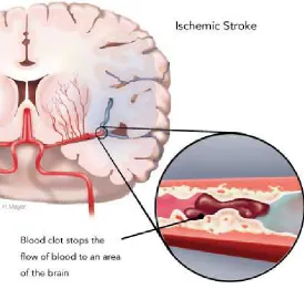
Figure 2.1 An Ischemic Stroke occurs when an artery to the brain is blocked by a
blood clot (Source: Heart and Stroke Foundation of Canada, 2008) ... 6
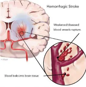
Figure 2.2: A Hemorrhagic Stroke occurs when a blood vessel ruptures and bleeds into the brain. (Source: Heart and Stroke Foundation of Canada, 2008) ... 7
Figure 2.3: The eight tasks performed at the Auto CITE workstation are reaching, peg board, supination/pronation, threading, tracing, object-flipping, fingertapping and arc-and-rings ... 13
Figure 2.4: The T-WREX is an weight reducing structure that has been designed to support an arm weakened by paralysis (Source: Housman et al, 2007) ... 16
Figure 2.5: The HOWARD was designed to help stroke sufferers regain strength and the use of their hand (Source: redOrbit, 2007) ... 17
Figure 2.6: The MIT-Manus is a highly function robotic rehabilitation device with 5 DOFs to exercise the shoulder, elbow and wrist (Source: Garrett, 2009) ... 18
Figure 3.1: It is envisioned that the device will be kept on a medium sized desk next to a computer. This image shows the relative size that the device could occupy compared to a laptop ... 21
Figure 3.2: Bone Structure of the Human Arm (Source: Wikipedia, 2010) ... 24
Figure 3.3: Side on view of the human elbow joint (Source: Medical Multimedia Group, 2001) ... 25
Figure 3.4: The three shoulder DOFs (Source: Hamill & Knutzen, 1995) ... 26
Figure 3.5: Elbow DOF (Source: Hamill & Knutzen, 1995) ... 27
Figure 3.6: The three wrist DOFs (Source: Hamill & Knutzen, 1995) ... 27
Figure 4.1: Caterpillar Skid Steer Loader control joystick (Caterpillar, 2010) ... 31
Figure 4.2: A common gaming joystick (Wikipedia, 2010) ... 31
Figure 4.3: A small Stewart Platform (Hexapod) (Source: Physik Instrumente, 2009) ... 33
Figure 4.4: A flight simulator base using a hexapod arrangement (Source: Atallah, 2000) ... 34
Figure 4.5: Haptics Device that can be used to train surgeons (SensAble Technologies, 2010) ... 35
Figure 4.7: Blythe Garrett's device designed as a USQ final year project (Source:
Garrett, 2009) ... 37
Figure 4.8: Concept 1 uses cables and pulleys to provide movement to a handle ... 38
Figure 4.9: Concept 2 uses rotational joints to provide horizontal and vertical movement ... 39
Figure 4.10: Concept 3 uses linear movement along 2 axes to cover the required ROM ... 41
Figure 4.11: A multi-turn potentiometer (RS Online, 2010) ... 42
Figure 4.12: Potentiometer Construction (Wikipedia, 2010) ... 43
Figure 4.13: A type of Digital Encoder (Digiball, 2006) ... 44
Figure 5.1: Shoulder flexion and extension (Source: Hamill & Knutzen, 1995) ... 46
Figure 5.2: Elbow flexion (Source: Hamill & Knutzen, 1995) ... 47
Figure 5.3: ROM with Arm Fully Stretched ... 48
Figure 5.4: ROM reduced by keeping the arm in front of the body... 49
Figure 5.5: ROM reduced again by allowing combined shoulder and elbow movements ... 49
Figure 5.6: Final design ROM – scenario 1 ... 50
Figure 5.7: Final design ROM – scenario 2 ... 50
Figure 5.8: Linear bearings and precision shaft (Source: SKF, 2010) ... 52
Figure 5.9: Ball and roller screw (Source: SKF, 2010)... 52
Figure 5.10: One style of rail guiding system (Source: SKF, 2010) ... 53
Figure 5.11: Example of an ‘off centre load’, where the load is applied at a distance from the axis of movement ... 54
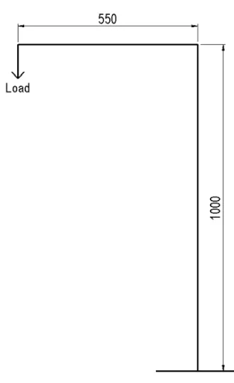
Figure 5.12: Illustration of a round cantilever experiencing a side load ... 57
Figure 5.13: Simplified model of structure ... 58
Figure 5.14: Deflection formula for a beam under a point load (Source: Beer et al. 2004) ... 58
Figure 5.20: 3D model of assembled RRD. ... 69
Figure 5.21: 3D model of exploded RRD assembly. ... 69
Figure 5.22: 3D model of assembled RRD from rear. ... 70
Figure 5.23: 3D model of Base; made from two piece of 20 mm aluminium plate ... 71
Figure 5.24: 3D model of Vertical Shaft; made from 50 OD x 3 mm wall aluminium
tube. ... 71
Figure 5.25: 3D model of Bearing Block; made from an 80 x 80 mm aluminium
block. ... 72
Figure 5.26: 3D model of Top Bar; made from aluminium plate and tube. ... 73
Figure 5.27: 3D model of End Bar; made from aluminium plate and tube. ... 73
Figure 5.28: 3D model of Horizontal Shaft; made from aluminium plate and tube. . 74
Figure 5.29: Example of using a rack and pinion to drive a potentiometer. ... 75
Figure 5.30: Example of using a gear and belt to drive a potentiometer. ... 76
Figure 5.31: 3D model of the assembly of the bottom Vertical Pulley Holder and
other components. ... 78
Figure 5.32: 3D model of Vertical Pulley Holder; made from aluminium plate, ... 79
Figure 5.33: 3D model of Potentiometer Pulley Shaft; made from steel bar. ... 79
Figure 5.34: 3D model of Potentiometer Mounting Plate; made from aluminium
plate. ... 79
Figure 5.35: 3D model of Spacer Bar; made from steel bar. ... 80
Figure 5.36: 3D model of the Vertical Belt Holder; made from aluminium plate. .... 80
Figure 5.37: 3D model of the assembly of the Horizontal Pulley Holder and other
components. ... 81
Figure 5.38: 3D model of horizontal pulley holder; made from aluminium plate. .... 81
Figure 5.39: 3D model of Vertical Cable Pulley Holder; made from steel plate. ... 83
Figure 5.40: 3D model of Vertical Cable Holder; made from steel plate. ... 83
Figure 5.41: PIC16F877A microcontroller used for the RRD (Source: Garrett, 2009)
... 84
Figure 5.42: Olimex PIC-MT-USB development board used for the RRD (Source:
Garrett, 2009). ... 85
Figure 5.43: Bourns 10 turn potentiometer ... 86
Figure 5.44: Resistor-capacitor filter circuit. ... 87
Figure 5.45: Photograph of the circuitry used for the position monitoring system. .. 88
Figure 6.2: Photograph of the LCD screen in rotation mode showing the relative
angel of each of the potentiometers. ... 93
Figure 6.3: Image of the interface screen immediately after device has been calibrated. ... 95
Figure 6.4: Image of the interface screen when arm is pushed away from the body and lowered, with the wrist extended, abducted and rotated. ... 95
Figure 6.5: Image of the interface screen when arm is pulled towards the body and raised, with the wrist flexed, adducted and rotated. ... 96
Figure 7.1: Photograph showing the bending that the top bar has experienced. ... 99
Figure 7.2: Photograph of new wrist device mounting arrangement. ... 100
Figure 7.3: Maximum vertical measurement. ... 103
Figure 7.4: Maximum horizontal measurement. ... 103
Figure 7.5: Minimum vertical measurement. ... 104
Figure 7.6: Minimum Horizontal measurement ... 104
Figure 7.7: Position 1 ... 106
Figure 7.8: Position 2 ... 106
Figure 7.9: Position 3 ... 107
Figure 7.10: Position 4 ... 107
Figure 7.11: Position 5 ... 108
Figure 7.12: Position 6 ... 108
Figure 7.13: Photograph of potentiometer mounting arrangement, specifically noting the lack of grub screw in the hole. ... 109
L
IST OF
T
ABLES
Table 3.1: Ranges of Motion of the seven DOFs of the arm (Source: Adapted from
Woodson et al. 1992) ... 28
Table 5.1: Comparison of features of linear bearings and rail guiding systems ... 55
Table 5.2: Properties of steel, aluminium and precision shaft ... 62
Table 5.3: Shaft diameters required for sound steel and aluminium structures ... 63
Table 7.1: ROM of wrist device after mounting changes. ... 102
Table 7.2: Measurements taken to deduce ROM ... 105
Table 7.3: Results for Horizontal Axis Testing ... 111
G
LOSSARY
CIMT: Constraint Induced Movement Therapy
DOF: Degree of freedom
DOFs: Degrees of freedom
FEA: Finite element analysis
RRD: Robotic rehabilitation device
ROM: Range of motion/movement
Chapter 1
I
NTRODUCTION
1.1
Introduction
Robotics and electronics have proven very beneficial in almost all industries and
areas of human life. There has been much research conducted recently into the use
of robotic devices for stroke rehabilitation. They are showing great promise in
restoring movement and strength to a patient’s paralysed limbs after suffering a
stroke.
This dissertation discusses how rehabilitation can greatly improve a sufferer’s
quality of life. The advantages of using robotic rehabilitation over traditional
methods are important drivers for this design. The dissertation documents the design
and construction of a computer-based device to help rehabilitate a patient’s upper
limbs.
This chapter discusses the project motivation, objectives and methodology as well as
outlining the structure of the dissertation.
1.2
Motivation
Stroke is a leading cause of disability and devastates the lives of sufferers as well as
their friends and family. One of the common side effects of stroke is paralysis of one
or more limbs. The limitations caused by the paralysis, and thus the quality of life of
the patient can be greatly improved with rehabilitation, but there are some problems
with the current techniques. It can be difficult for patients to receive enough therapy
to improve their condition because of its high expense, the need to travel and a lack
of therapists. An inexpensive robotic device that can be used in the home has the
potential to help many less fortunate sufferers regain movement and strength in their
arm, thus reducing their reliance on others. Family and friends are usually left with
the heavy strain of looking after stroke victims so helping stroke patients also helps
The aim of this project is to design and manufacture an effective yet inexpensive
robotic device that can be used for rehabilitating stroke survivors who have arm
paralysis. It is intended that the device will be purchased by the patient and kept in
their home so that they can use it at any time. It will not replace physiotherapists
completely; instead it will supplement their work to achieve better results for the
patients.
1.3
Project Objectives
In order to guide the project, a list of objectives has been devised. They have been
arranged in order of when they will be achieved and are shown below;
1. Research how stroke affects movement and motor skills. Research
current rehabilitation methods and their success.
2. Research available joystick style equipment and their mechanisms,
and determine whether they could be suitable for this device.
3. Create concepts and investigate the strengths and weaknesses of each
concept.
4. Prepare design for construction
5. Investigate and design electronics and control.
6. Test the design and evaluate its performance.
As time permits:
7. Investigate and design force feedback components.
8. Perform clinical testing and provide professional feedback.
The methodology needed to ensure these objectives are achieved in a timely fashion
will be discussed next.
currently used methods will be investigated. The possibility of using robotic
rehabilitation devices will be explored and some recently developed devices will be
discussed. Arm movements and ranges of motion will be examined.
Using the background information, the constraints and requirements of the device
will be determined. Some concepts for the structure will be devised and critiqued.
Position monitoring systems will be considered at this point, but designed in detail
later. The best concept will be designed, components drafted and drawings given to
the workshop for construction. Parts to be outsourced will be specified and ordered
through USQ. Once built, the structural part of the device will be tested and
evaluated and changes may be made if necessary.
The position sensing of the device will then be designed in detail. The parts will be
fitted to the device along with any electronics that are required. The electrical circuit
will be designed and implemented. The software and interface needed to make the
position of the device visible on a computer screen will then be developed.
The device will be evaluated as an overall stroke rehabilitation tool. Problems will be
identified, possible solutions/modifications will be suggested and the future work
needed will be outlined.
1.5
Overview of Dissertation
This section outlines the information that is included in this dissertation. The
chapters and their content are listed below;
Chapter 2, Background, investigates stroke and its effects along with rehabilitation
objectives and techniques. It also introduces robotic rehabilitation and looks at some
of the recently developed devices.
Before design can begin, the requirements of the device and the design constraints
need to be known. Chapter 3, Design Constraints and Requirements, contains this
information.
Chapter 4, Concept Development, covers some of the concepts that were devised and
In chapter 5, Final Design and Manufacture of Prototype, the design process and the
workings of the device are documented. Included in this chapter is the design of the
mechanical structure and the electronics.
The development and operation of the software and interface is detailed in chapter 6,
Software and Interface.
Chapter 7, Evaluation and Testing of Design, will look at the functionality of the
design and identify any problems that were found. It will also cover the range of
movement and accuracy testing.
Finally, a summary of the achievements that have been made and the future work
that can be done on this project will be included in chapter 8, Conclusions and
Future Work.
1.6
Conclusion
The need for a better stroke rehabilitation technique has sparked research into using
robotic devices for physical therapy. An effective device could help patients recover
from their paralysis much better than traditional techniques, making them less
dependent on carers and giving them better quality of life. This chapter has set out
Chapter 2
B
ACKGROUND
2.1
Introduction
The following chapter discusses the information found while conducting a literature
review on stroke. The topics include stroke and its effects, rehabilitation goals and
techniques, neuroplasticity and muscle development. The research then moves onto
robotic rehabilitation and its effectiveness, and some of the recently developed
devices. An understanding of stroke and rehabilitation was necessary to design a
device that meets the needs of the patients.
2.2
Stroke
Stroke (also known as cerebrovascular disease) occurs when the supply of blood to
the brain is suddenly disrupted. (National Stroke Foundation, 2007). Blood flows to
the brain by a network of blood vessels called arteries, and is responsible for
transporting oxygen and nutrients to brain cells. When the blood flow is cut off, the
brain cells don’t receive the supplies they need and die. Depending on the extent of
the stroke, and the length of time before medical help is received, part of the brain
can become permanently damaged. This damaged part is referred to as an infarct.
The part of the body that the infarct controlled, will no longer work properly, or not
at all.
2.3
Stroke Statistics
The National Stroke Foundation (2010), have listed a number of statistics on their
website. The ones that are useful for this report are listed below;
• Stroke is Australia’s second single greatest killer after coronary heart disease and a leading cause of disability.
• In the next ten years more than half a million people will suffer a stroke.
• About 88 per cent of stroke survivors live at home and most have a disability.
The numbers presented here show the significant effect that stroke has on society.
The Australian Bureau of Statistics constantly reports an ageing population which
will correlate to an increased number of stroke sufferers in coming years.
2.4
Types of Stroke
There are two main types of stroke; ischemic and hemorrhagic, and they are
classified by the way the blood flow to the brain is interrupted.
An Ischemic stroke (Figure 2.1) occurs when an artery to the brain is blocked either
by a blood clot that has formed at the site of the blockage (cerebral thrombosis) or at
another location in the body (cerebral embolism). These blood clots are formed
[image:23.595.179.453.376.637.2]A hemorrhagic stroke (Figure 2.2) occurs when a blood vessel ruptures and bleeds
into the brain. According to the American Heart Association (2010) thirteen per cent
of all strokes are hemorrhagic strokes. When the weakened blood vessel ruptures, the
blood pools and presses on the nearby brain tissue, killing brain cells. The blood
vessel can rupture inside the brain, known as an intracerebral hemorrhage or on the
[image:24.595.177.457.212.495.2]outside of the brain, a subarachnoid hemorrhage.
Figure 2.2: A Hemorrhagic Stroke occurs when a blood vessel ruptures and bleeds into the brain. (Source: Heart and Stroke
Foundation of Canada, 2008)
2.5
Effects of Stroke
Each stroke is different, and the effects depend on the size of the stroke and where in
the brain it occurs. The American Heart Association (2010) lists some of the
common disabilities caused by stroke including problems with;
• the senses (eyesight, touch, awareness of the body);
• speaking and understanding speech;
• eating;
• sexuality;
• behaviour, thinking, emotions; and
• weakness or paralysis of the body (hemiplegia).
If the stroke occurs in the right hemisphere of the brain, it can cause paralysis of the
left hand side of the body and problems with depth perception. Patients can
experience loss of judgement and act impulsively, suffer short term memory loss and
visually neglect the space on the left side of their body (left side neglect).
If the stroke occurs in the left hemisphere, it can cause paralysis of the right hand
side of the body, speech and language problems as well as behavioural and memory
problems. In the opposite way to right hand hemisphere stroke sufferers having an
impulsive behaviour and losing their sensible judgement, left hand hemisphere
patients may have a slow behaviour and not be able to finish tasks because of it.
Patients who have a stroke in their brain stem lose the part of the brain that controls
breathing, blood pressure and heart rate. They can experience problems with these
functions as well as paralysis, vision impairment, difficulty swallowing and hearing
and speech problems.
Strokes that occur in the cerebellum can cause loss of coordination and balance,
dizziness, nausea and vomiting. (Brain Foundation, 2010)
Generally stroke can have a devastating effect on one’s personality. It can cause the
patient to become distressed, irritated, depressed, overly emotional or to feel
helpless. It can make what were once simple tasks very complicated and this can be
difficult to come to terms with for some sufferers.
2.6
Rehabilitation
The Pocket Macquarie Dictionary (1989, p. 873) defines ‘rehabilitate’ as, to educate
and help (a person affected by an accident or disease) to take up normal activities
again. The following section discusses the reason for rehabilitation, the currently
used techniques and the issues associated with them.
2.6.1
Reason for Rehabilitation
Stroke can drastically reduce a person’s quality of life because of its debilitating
side-effects. The type and amount of rehabilitation required depends on the severity
of the stroke and what parts of the body it has affected. In Australia, rehabilitation
can be received in hospital, at home, or as an outpatient (National Stroke Foundation,
2007). Rehabilitation needs to start as soon as possible after the stroke, and can be
within 2 days of the attack if the patient is stable (Brain Foundation, 2010). There are
several rehabilitation techniques and these will be discussed in the following
sections.
A rehabilitation team can consist of some or all of the following people; doctors,
nurses, dieticians, occupational therapists, physiotherapists, psychologists, social
workers and speech pathologists (National Stroke Foundation, 2007) Obviously, the
professionals involved will depend on the problems the patient experiences.
2.6.2
Rehabilitation Goals
The aim of rehabilitation is to help the patient regain as much independence as
possible (Heart and Stroke Foundation of Canada, 2009) and to improve the patient’s
quality of life after the stroke. It helps to learn skills that have been lost or if this
isn’t possible, patients will be taught new skills to cope with the changes to their
lifestyle (National Stroke Foundation, 2007). The rehabilitation goals will depend on
the severity of the stroke, and its effects on the patients. For a stroke that has caused
speech problems, rehabilitation will focus on helping the patient to communicate. If
the stroke has caused paralysis to one or both sides of the body, rehabilitation will
could mean the difference between a patient being able to open a bottle themselves,
and having to rely on someone else to do it. Rehabilitation can last for months or
years depending on the person.
Recovery is usually greatest in the first couple of months after the stroke and then
gradually plateaus, but small gains can be experienced long after the stroke (Brain
Foundation, 2010).
2.6.3
Neuroplasticity
Neuroplasticity is the brain's ability to reorganize itself by forming new neural
connections throughout life (MedicineNet.com, 2004). Humans are always learning
new skills, and experiencing new things. The human brain is able to adapt to these
things by training different neurons to control different parts of the body and
remember different things. Neuroplasticity is the saving grace of the damaged or
disabled brain; without it, lost functions could never be regained, nor could disabled
processes ever hope to be improved (MemoryZine, 2009). After a stroke, parts of the
brain can be damaged and the function that these parts controlled will be lost.
However, because of neuroplasticity, a different part of the brain can be trained to
take over the lost functions. For example, if the left side of the brain is damaged
from stroke causing paralysis of the right side of the body, the right side of the brain
can be trained to control the bodily functions. Retraining the brain takes time and
constant repetition of the task.
Carey (2007) listed the principles of retraining a damaged brain based on perceptual
learning and neural plasticity theories. They are;
• repeated practice of specific stimuli;
• attentive exploration;
2.6.4
Muscle Development
Muscle atrophy is the wasting of muscles resulting from disuse, or disease (also
called neurogenic atrophy). Disuse is generally related to things like decreased
activity as aging occurs or suffering an injury that prevents use of a body part for
some time. Muscle atrophy caused by stroke falls under the disease category as the
inability to move is caused by the problems with the nerves that supply the muscles.
The most common form of treatment for muscle atrophy is an exercise program
designed by a physical therapist. However, in order to exercise the limbs, the patient
must first be able to use them. Muscle development would be the final stage of
stroke rehabilitation and can only begin once the patient has regained movement in
the affected limb. (MD Guidelines, 2010)
2.6.5
Current Rehabilitation Techniques
The majority of rehabilitation received is currently through physical therapy.
Another recently developed technique called Constraint Induced Movement Therapy
is also being more widely used. These will be discussed further below.
2.6.5.1 Rehabilitation by Physical Therapy
As discussed earlier, there are many professionals that can be involved with the
rehabilitation process. This report is mainly concerned with trying to recover the
movement of the patient’s arm, which is presently done by a physiotherapist. This
section will only discuss the techniques used by a physiotherapist to regain
movement of a limb.
In Australia, physical therapy is currently the most widely used technique for
recovering limb movement. It is the most accessible treatment and offers reasonable
results. Physiotherapy can include some or all of the following;
• practicing day to day activities like rolling in bed, standing up, walking and using legs and arms;
• exercises to improve strength, sensation, coordination and fitness;
• choosing to limit the use of the patient’s good limb to encourage use of the affected limb.
(National Stroke foundation, 2008)
The therapy program depends on the patient and will be determined by medical
professionals. The exercises will change over time as the needs of the patient change.
2.6.5.2 Constraint Induced Movement Therapy
Constraint Induced Movement Therapy (CIMT) or CI Therapy is a fairly new
technique developed by Edward Taub. It involves constraining the unaffected arm
with a sling and forcing the use of the affected arm for day to day activities. Usually
after a stroke that causes arm paralysis, the patient will neglect using the affected
arm and hence never regain any movement of it. CIMT utilises the theory of
neuroplasticity and retrains the brain to move the impaired arm.
Taub & Guswatte (2006) give the three main components of CIMT. They are;
repetitive, task-oriented training of the impaired arm for several hours a day for
10-15 days, constraining patients to use the impaired arm during waking hours and
applying a package of behavioural messages designed to transfer gains in a clinical
setting to the real world. Over the last 20 years, a large body of evidence has
accumulated to support the efficacy of CI therapy for hemiparesis subsequent to
chronic stroke (Taub & Guswatte, 2006).
Following on from the research into CIMT, a need to automate the treatment has
been recognised, to try and make it administrable in the home. This is necessary to
reduce the amount of one-on-one physical therapy required, in turn reducing the cost
of such a beneficial treatment and making it more easily available for the wider
community. This has led to the development of Automated Constraint Induced
rings. A computer records the patient’s ‘score’ for each task and compares his or her
scores during the training.
Figure 2.3: The eight tasks performed at the Auto CITE workstation are reaching, peg board, supination/pronation, threading, tracing,
object-flipping, fingertapping and arc-and-rings
2.6.5.3 Issues with Current Rehabilitation Techniques
There are number of problems associated with current stroke rehabilitation
techniques, mainly physical therapy. DeAngelis (2010) reported that less than ten
percent of people who had suffered a stroke were still receiving occupational or
physical therapy within two years of their attack. This is because therapy is a very
expensive and time consuming treatment. In order to reap significant benefits from
physical therapy, the patient must frequently see a physiotherapist. This can be
difficult for some patients who live a significant distance from the clinic or must rely
on family or friends to drive them. These factors cause great inconvenience and
place a lot of pressure on the patient and their family.
Another major problem with physical therapy is that the patient might be showing
promise of independence within the hospital or facility but once they get home, the
skills don’t transfer and the patient must still rely on family or friends. If the skills do
transfer, they usually aren’t reinforced when the patient returns home and can
Stroke rehabilitation will usually involve practicing repetitive movements. This can
be boring for both the therapist and the patient, causing them to lose interest in what
they are doing.
2.6.6
Measuring Rehabilitation Progress
An important part of any rehabilitation program is monitoring the progress of the
patient in order to address problems with certain areas. It is paramount that the
patient moves forward with their disability and not backwards which sometimes
happens because of lack of motivation or improper treatment.
There is a variety of tests and scales that are used by therapists to monitor the
progress of a patient. They can be a measure of range and speed of movement, or a
subjective rating of a patient’s ability to perform tasks. The Manual Muscle Test
involves a therapist testing the strength of a limb. The Fugl-Meyer assessment
consists of a therapist noting the general use, reflex, range of motion (ROM),
balance, sensation and other behaviours associated with the affected limb.
2.7
Robotic Assisted Rehabilitation
Robotic rehabilitation has been an active field of research since the 1990s (Celik et
al. 2010). Restoring arm movement after a stroke usually requires teaching specific
movements then constantly repeating them. This sort of work can easily be done by a
robotic device. It is important to note that a robot will not necessarily replace a
therapist but will probably supplement their treatment. Some different types of
robotic devices have been created and tested, and studies have shown that they give
results similar to or better than physical therapy.
• An in-home device relieves the need for travelling to a physiotherapist and allows the patient to do the exercises whenever he or she can.
• Robotic devices are consistent and objective when assessing and guiding a patient.
• With the use of games or activities, robotic devices can make the rehabilitation more fun and exciting.
• Correct movements can be forced by locking certain degrees of freedom (DOFs). Exercise programs can be developed as required by therapists.
• With the aid of force feedback, the nature of the device can be changed from resistive, to neutral to assistive more accurately and consistently than by a
therapist.
However there are some limitations with robotic devices and these need to be
discussed as well.
2.7.2
Limitations
The limitations associated with robotic rehabilitation are;
• Exercises that can be done on a robotic device may not correlate directly to activities of everyday living such as opening a jar (Casadio et al. 2009).
• Robotic devices do not have give the human interaction of one on one therapy.
• There is not yet a correlation between robotic measurements and patient progress. (Celik et al, 2008)
Research has shown that the advantages of robotic assisted rehabilitation outweigh
the limitations and that robotic devices have a very important role in the society.
2.7.3
Recently Developed Devices
There is a lot of research being conducted into using robotic assisted rehabilitation
and several different devices have been designed. Some devices have been put into a
clinical situation and initial testing has been conducted. Three of the recently
2.7.3.1 T-WREX
The T-WREX or the Therapy Wilmington Robotic Exoskeleton shown in Figure 2.4
is a weight reducing structure that has been designed to support an arm weakened by
paralysis. The structure counterbalances the weight of the entire arm without the use
of actuators to enable the user to move around easily and not have to support their
bodyweight. It offers approximately two thirds of the full ROM of an average arm
and has five DOFs. The amount of support the device gives can be varied by adding
or removing rubber bands.
Figure 2.4: The T-WREX is an weight reducing structure that has been designed to support an arm weakened by paralysis (Source:
Housman et al, 2007)
2.7.3.2 HOWARD
Figure 2.5: The HOWARD was designed to help stroke sufferers regain strength and the use of their hand (Source: redOrbit, 2007)
2.7.3.3 MIT-Manus
The MIT-Manus (Figure 2.6) is a robotic rehabilitation device developed by the
Massachusetts Institute of Technology. It initially had two DOFs and could move in
2D horizontal plane. A wrist attachment with three DOFs was later added to exercise
the wrist as well. The initial device was completed in 1991 and it has been worked
on since. It is now a highly functional device that is coupled to a computer and uses
force feedback to assist or resist patient movements. The computer displays the
position and movements of the handle and provides exercises for the patient.
Clinical testing has been conducted with this device (without the wrist attachment) at
the Burke Rehabilitation Hospital in New York and the results were quite promising.
Patients showed reduced movement impairment in their elbows and shoulders.
Figure 2.6: The MIT-Manus is a highly function robotic rehabilitation device with 5 DOFs to exercise the shoulder, elbow and
wrist (Source: Garrett, 2009)
2.8
Interview with Jude Wilson – Physiotherapist
In June 2010, a casual interview was conducted with Jude Wilson, a physiotherapist
who was worked with stroke patients, to obtain a clinical opinion of the device in
mind. Jude’s overall view was that the device was good idea and would definitely be
a valuable tool for stroke rehabilitation. Jude also brought up some points that
reinforced the literature found in other research material.
• The device needs to provide functional movements that correlate to everyday living.
• The best way to regain movement is by repeating movements over and over again.
Jude was a helpful reference as the opinions and ideas of someone who has worked
directly with patients are very valuable in the design process.
2.9
Conclusion
Stroke is a leading cause of disability and one of its effects is paralysis in the limbs.
This causes sufferers to lose their ability to do simple, everyday tasks and hence
makes them very dependent on others. Rehabilitation aims to reverse this paralysis,
and help the patient re-learn movements, increase muscle strength and improve
motor skills. This is currently done by physical therapy, but new advances in robotic
Chapter 3
D
ESIGN
C
ONSTRAINTS AND
R
EQUIREMENTS
3.1
Introduction
The following chapter covers the requirements of a fully functional robotic
rehabilitation device that is ready for production and sale. Not all of these
requirements will necessarily be met in this project, but they will be considered and
developed as future work. The constraints need to be established early so that a
suitable device is designed. The most important feature of the intended device is its
home-based nature. This suggests a low cost, small and effective design.
3.2
Requirements of a Robotic Rehabilitation Device
The following section lists the major requirements of a robotic rehabilitation device
(RRD). Each one will be addressed in detail.
3.2.1
Size, Form & Portability
It is intended that the RRD to be designed will be owned by a patient and kept in his
or her home. It could also be kept at a physiotherapy clinic for use during
appointments. It should be easily accessible and set-up should be quick and simple
so as to not create another tedious task. The device could be kept on a computer desk
with a computer and be set up at all times (Figure 3.1). This gives a rough idea of
how big the device can be, but a quantitative maximum size window would be
approximately 500 mm wide, 1000 mm deep and 1500 mm high. One would assume
that the only times the device would be moved is if the room needs to be rearranged
or if the patient is moving house, meaning portability isn’t a major issue. The form
Figure 3.1: It is envisioned that the device will be kept on a medium sized desk next to a computer. This image shows the relative size that
the device could occupy compared to a laptop
3.2.2
Movement
The RRD will need to have movements that mirror the human arm. The particular
movements will be discussed more in a later section but the mechanisms controlling
these movements will be discussed here. The device will be made up of mechanical
joints, either linear or rotational, that will need to be smooth and consistent. They
should be precise and repeatable and be as neutral as possible, so quality
manufacturing and design will be required.
3.2.3
Cost
It is intended that this device will be owned by the patient. To make this realistic, the
device needs to be cheap relative to therapy costs and the results that it gives. There
is a fair scope for price, depending on the final design and its application. By owning
this device, the patient reduces the amount of therapy they need and can use the
money they are saving to buy a RRD.
3.2.4
Position Monitoring
One of the requirements of the device is that it can track the patient’s movement at
software to monitor their progress and to give them objectives to complete. It will
also be necessary for adapting force feedback to the device.
3.2.5
Force Feedback
It is desirable to have force feedback on a RRD, in order to take patients through the
whole range of rehabilitation; teaching movements, refining motor skills and
increasing strength. Assuming a patient has lost nearly all of their movement, they
will need to first learn movements without having to apply force, and then once this
is done, they will need to learn to move their own body weight. From here, they can
keep building muscle and move heavier and heavier objects. There are many ways in
which force feedback could be used to increase the effectiveness of this device. It
could be used to replicate gravitational forces, simulate friction, obstacles etc.
3.2.6
Lockable movements
It is necessary that certain DOFs can be locked, to focus on particular movements. A
physiotherapist would devise a suitable routine, locking and unlocking DOFs as
required. Certain arm muscles and movements could be targeted depending on the
patient and their condition.
3.2.7
Measuring Movement & Progress
The reason for rehabilitation is to help patients improve and progress. In order for a
physio to help the patient, they need to know where the patient is up to and which
areas need improvement. It is important that the device can map progress over time.
It could do this by measuring strength, ROM, speed, reaction times, accuracy etc.
and it will probably be limited by the electronic hardware. The device will act like a
generic joystick being used to play a computer game, just with a larger ROM.
3.3
Design Constraints
It should be noted that the device to be designed is not supposed to be a completed,
fully functioning device. This device is a proof of concept prototype only and may
not fulfil all of the requirements of one that is ready for production. Low cost and
simple mechanisms will be pursued to prove that concepts will or will not work and
determine how they can be developed.
For this project, the main design constraints that will be considered are size,
movement, lockable movements, position monitoring, cost and adaptability of force
feedback. The proof of concept device will be refined as future work to meet the
remaining requirements.
One of aims of this project is to test the ease of which the wide ROM of the shoulder
and arm can be captured and it will be sufficient to test this in two dimensions and
not three. Therefore the major movements of the device will be kept to a single two
dimensional plane. This may mean one of the shoulder’s DOFs will not be included
in the device’s movements however simplicity will be maintained while testing the
concept of using a RRD.
The biomechanics of the human arm need to be examined so that a suitable ROM
can be established for the device.
3.4
Movement of the Human Arm
The human arm is a very flexible and useful tool. This section will introduce the
basic structure and mechanics of the human arm in order to understand its ROM.
3.4.1
Basic Anatomy
Human anatomy is quite complex when the body is considered as a complete
arm will be simplified in order to understand how a rehabilitation device should
work.
A joint is where two or more bones touch and/or articulate. The human arm gets its
dexterity from its three main ‘freely movable’ joints; the shoulder, elbow and wrist
(Figure 3.2). The bones that make up a freely movable joint are held together by
bands of tissue called ligaments.
Figure 3.2: Bone Structure of the Human Arm (Source: Wikipedia, 2010)
Movement is given to the joint by a muscle or group of muscles that are attached to a
bone on both sides of the joint. When given a signal from the brain, a muscle
contracts, pulling the bones of a joint together in one direction. To move in the other
direction, an opposing set of muscles on the opposite side of the joint need to
contract. Take for instance the elbow joint, which is referred to as a hinge joint. It
muscle, which attaches to the opposite side of the bones contracts; it will pull the
Radius and Ulna down. Nerves in the arm receive signals from the brain and tell the
muscles when to contract, and when to relax.
Figure 3.3: Side on view of the human elbow joint (Source: Medical Multimedia Group, 2001)
3.4.2
Degrees of Freedom
The shoulder is a ball and socket joint. It has three DOFs; shoulder
flexion/extension, shoulder adduction/abduction and shoulder rotation –
lateral/medial shown in Figure 3.4.
The elbow (Figure 3.5) is a hinge joint. It has one DOF; elbow flexion.
The wrist (Figure 3.6) is a more complicated joint. It is a form of gliding joint known
as the ellipsoid joint. Hamill & Knutzen describe the wrist as having two DOFs;
wrist flexion/extension and wrist adduction/abduction. A third degree, which is
The human arm as a whole has a total of seven DOFs, which can all be used
simultaneously.
Figure 3.5: Elbow DOF (Source: Hamill & Knutzen, 1995)
3.4.3
Range of Motion
Table 3.1 shows the ROMS of each of the arm’s DOFs. These values are average
ranges of the male air force personnel, who are usually in peak physical condition,
and would have more movement than the average person.
Table 3.1: Ranges of Motion of the seven DOFs of the arm (Source: Adapted from Woodson et al. 1992)
Movement Range of Motion
(degrees)
Shoulder Flexion 188
Shoulder Extension 61
Shoulder Adduction 48
Shoulder Abduction 134
Shoulder Rotation – Lateral 34
Shoulder Rotation – Medial 97
Elbow Flexion 142
Forearm Supination 113
Forearm Pronation 77
Wrist Flexion 90
Wrist Extension 99
Wrist Adduction 27
3.5
Conclusion
An ideal device needs to have the following features and characteristics;
• be small enough to fit in the patient’s home;
• covers the movement of a human arm;
• has a position monitoring system;
• movements can be locked;
• progress can be monitored;
• has 3D games;
• low cost; and
• has force feedback.
However, the device that will be constructed for this project will only address the
need to; be small, be low cost, cover most of the human arm movement, have a
position monitoring system and have lockable movements. The DOFs and the ROM
Chapter 4
C
ONCEPT
D
EVELOPMENT
4.1
Introduction
The idea of using a presently available hand control device and modifying it to meet
the requirements discussed in chapter 3 was investigated to save manufacturing
costs. A device that met these meets was not found, so several concepts for a new
RRD were devised. This chapter discusses the various conceptual designs and how
they were critiqued to find the best options for both the structure and the position
monitoring system.
4.2
Presently Available Hand Control Devices
A good way of reducing cost is to use commercially available parts instead of
designing and constructing them. This section investigates joysticks and hand control
devices that are on the market, and their applicability to the required device.
4.2.1
Joystick
Joysticks for computer gaming have been around for years but they are always being
developed to increase the authenticity of the playing experience. Joysticks are also
used to control various sorts of machinery, aeroplanes, remote controlled devices and
many other things. Figure 4.1 and Figure 4.2 show joysticks from a Caterpillar Skid
Figure 4.1:Caterpillar Skid Steer Loader control joystick (Caterpillar, 2010)
Figure 4.2: A common gaming joystick (Wikipedia, 2010)
The Caterpillar joystick has 2 DOFs and several buttons which are pushed with the
thumb. It can move side to side and backwards and forwards. Many industrial
meaning the amount the joystick is moved is relative to the amount of function that
is performed. For example, if the forward movement of the joystick is used for
moving the machine forward, when the joystick is moved a small amount, the
forward speed will be low, but if the joystick is moved all the way forward, the
machine will move at maximum speed.
The gaming joystick pictured has 3 DOFs as well as several other buttons. It can
move side to side, backward and forward and the handle can also rotate in the Z axis.
Gaming joysticks usually offer any combination of the X and Y movements, for
example, diagonally forward. Some joysticks have a form of force feedback built
into them. It is usually quite simple, and gives resistance to movement, or a vibration
sensation.
Suitability of a Joystick
Joysticks can offer the three DOFs of the wrist but unfortunately not those of the
elbow and shoulder. The ‘force feedback’ does not offer the assistive and resistive
forces over the full ROM that is required for a RRD. It would be very hard to add
force feedback to commercially available joysticks because they are not very easy to
modify. Joysticks that are robust enough for this application are available and might
be similar to the one pictured in the skid steer loader. Overall, a joystick is not
suitable for a RRD because it would not be easy enough to adapt it to a design and
would require too much modification to make it worthwhile.
4.2.2
Stewart Platform (Hexapod)
A Stewart Platform (Figure 4.3) is a parallel kinematic mechanism consisting of two
plates joined by six actuators. The movable plate or platform can travel in 6 axes; 3
translational and 3 rotational. Being a parallel mechanism, all of the actuators work
example, Physik Instrumente (2010) make and sell hexapods with capacities from 5
kg to 1000 kg and up to 200 mm travel in the X and Y axis. This is just a small range
of the current market though.
For the purpose of a RRD, a handle could be attached to the moving plate, so that a
patients hand can control the position of, for example, a cursor on a computer screen.
Suitability of a Stewart Platform
A Stewart Platform would be able to offer all of the DOFs required for a RRD
however it would be very difficult to lock certain ones if required. As stated, Stewart
Platforms would be ideal in terms of precision and smoothness however this
corresponds to their high cost. They also have a limited range of travel. A Stewart
Platform would be quite adaptable in terms of mounting, programming and adapting
force feedback however their high cost, limited ROM and inability to lock
movements makes them unsuitable for this application.
Figure 4.4: A flight simulator base using a hexapod arrangement (Source: Atallah, 2000)
4.2.3
Haptic Devices
Haptic devices are those that can transfer the sensation of touch from a virtual,
computer based world to the user. Haptic devices are used in situations where a user
requires feedback from a system to make the experience more realistic for a variety
of reasons. This is very difficult thing to do, and is currently being extensively
researched. Typically, the haptic device will use programmed actuators to exert a
force or vibration on the user simultaneously with an action on a computer screen or
in a virtual world in an attempt to make it seem more real. The particular model
shown in Figure 4.5 is made by SensAble Technologies, and has 6 DOFs. It is being
used for training surgeons as shown in Figure 4.6. The reason for using one of these
haptics devices is that the student feels like he or she is cutting into a real human
movements. They can be purchased with force feedback and software but are
expensive and may be difficult to adapt to.
Figure 4.5: Haptics Device that can be used to train surgeons (SensAble Technologies, 2010)
Figure 4.6: A Haptics Device being used to train a surgeon (Lyons, 2009)
4.2.4
Conclusion
None of these commercially available products are idea for an RRD. They all offer
is that none of them offer the ROM that is required to exercise the whole human arm.
Cost also precludes the Haptic devices and Stewart Platform. From this research, it
was concluded that a new device needed to be designed to meet the needs of this
particular application. Concepts were developed and will be discussed in the
following sections.
4.3
Previous Work at USQ
Blythe Garratt was a final year Bachelor of Mechatronic Engineering at USQ
Toowoomba campus in 2009. His final year project is titled ”The Development of a
Wrist Rehabilitation Device for Movement Therapy” and its focus was the design
and development of a therapy device to assist physiotherapists in the rehabilitation of
a patient’s wrist strength and motor control which have been impaired by stroke. His
work is similar to that being done in this project however Garratt only looked at
rehabilitation of the wrist. His work proved successful as he designed and
constructed a device which captures natural human wrist movement over a large and
complex ROM with a mechanical structure that is well suited to the biomechanical
behaviour of the wrist (Garratt, 2009).
Garratt’s wrist device (Figure 4.7) consists of a mechanical structure, electronics,
and interface software. It is available to me and I have been encouraged to use it in
my design if possible. No better options have been found so at this stage, so the wrist
device will be attached onto a structure that will accommodate for elbow flexion,
Figure 4.7: Blythe Garrett's device designed as a USQ final year project (Source: Garrett, 2009)
4.4
Concepts of Structure
A system of joints will be needed to cover the six of seven DOFs of the arm, and for
simplicity, these have been broken up into the wrist and shoulder /elbow parts. The
shoulder /elbow structure has been conceptualised as a standalone assembly and the
wrist device will be attached to it. The patient will hold or be strapped to a handle
that is part of the wrist assembly.
4.4.1
Concept 1 – Cables and Pulleys
This design pictured in Figure 4.8, uses a simple cable and pulley system to support
the patients arm while they hold the handle. The handle is connected to one end of
the cable and the weight block is connected to the other end. The handle is free to
move in any direction possible and its weight is counterbalanced by the weight
block. The pulleys would be attached to the ceiling or a high shelf of some sort, or a
Figure 4.8: Concept 1 uses cables and pulleys to provide movement to a handle
Strengths
• it is a very simple design involving few parts.
Weaknesses
• position monitoring would be very difficult;
• adding force feedback would be virtually impossible; and
• there is no way to limit or lock movements.
flexion/extension and elbow flexion respectively. Blythe’s wrist device can be
attached to the face plate shown in the model. The joints would have ball bearings
for minimal friction and be as precise as practical. The base plate would be clamped
to a desk and the patient would sit in a height adjustable chair in front of it.
Figure 4.9: Concept 2 uses rotational joints to provide horizontal and vertical movement
Strengths
• it wouldn’t require any expensive parts except ball bearings;
• has limited precision manufacturing;
• it is a simple design; and
• it offers easy mounting of wrist device.
Weaknesses
• position monitoring is certainly possible but could become complex depending on the system used;
• force feedback would be difficult to adapt as each joint depends on the other one; and
• possible buckling and rigidity problems.
4.4.3
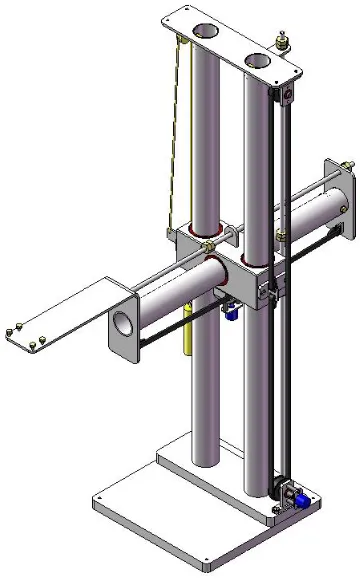
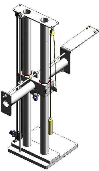
Concept 3 – Linear Shafts
This design (Figure 4.10) consists of a central bearing block that can move up and
down on two vertical shafts. There is a third shaft that can move horizontally in and
out of the bearing block. This combination gives horizontal and vertical translation
in a 2D plane, which corresponds to shoulder flexion/extension and elbow flexion.
The wrist device would be attached to the end of the horizontal shaft, and provide the
three wrist movements and shoulder rotation. The design would incorporate a
locking mechanism for the vertical and horizontal movements. As with concept 1,
the base plate would be clamped to a desk and the patient would sit in a chair to
operate the device.
Strengths
• it would give very precise movements in both directions, providing it is well manufactured;
• easy to fit a locking mechanism, or even a movement limiting mechanism; and
• device could be very robust with appropriate material selection.
Weaknesses
Figure 4.10: Concept 3 uses linear movement along 2 axes to cover the required ROM
4.5
Concepts of Position Monitoring
Position monitoring is an essential part of a RRD. It needs to be accurate and reliable
in order to control software and correctly assess patient’s progress. It should be noted
here that in previous work, potentiometers have been used for position monitoring of
rotating components.
4.5.1
Concept 1 – Potentiometers
A potentiometer (Figure 4.11), usually called a ‘pot’ is a simple electronic
component that is used as a rheostat or variable resistor. As shown in Figure 4.12,
they consist of a resistive element that has a cylindrical shape. A wiper is connected
to the input shaft and contacts on the resistive element. A voltage drop across the
Potentiometers can be single turn, which gives slightly less than 360o of rotation or
up to about 20 turn, offering about 7200 o of rotation. For standard applications, their
resistance can range anywhere from 1 Ω, to 5 MΩ.
Potentiometers can have a linear or logarithmic taper. In linear potentiometers, the
output voltage is linearly proportional to the position of the wiper. They are used in
applications like position control where the output needs to be linear. Logarithmic
potentiometers have a logarithmic output and are used for things like audio volume
control.
Figure 4.11: A multi-turn potentiometer (RS Online, 2010)
Strengths
• fairly inexpensive;
• easy to implement;
Weaknesses
• offer rotation which needs to be converted to linear movement if necessary.
Figure 4.12: Potentiometer Construction (Wikipedia, 2010)
4.5.2
Concept 2 – Linear Encoders
Linear encoders are used to detect position in a linear axis and utilize properties
including optical, magnetic, inductive, capacitive and eddy current. Most of them,
including the one shown in Figure 4.13 work by using a readhead to measure a
certain aforementioned property, whether it be light, magnetic field etc along a strip
or shaft, and then give an output which can be used to determine the position of the
readhead relative to a fixed point.
Encoders can be either incremental or absolute. An absolute encoder gives a unique
signal for each position, whereas an incremental encoder only gives a change in
position between increments and calculations need to be done to determine position.
Linear encoders are used for a variety of applications from digital callipers to high
Figure


Related documents
Different joystick and how they work were studied, which enabled the creation of the concept design which lead to the final design of the force feedback joystick for the
The purpose of the study was to assess the extent to which training using the Bimanual Arm Trainer (BAT) is effective in improving arm function in stroke patients as measured by the
Evans, Nicole M., "The Process of Exercise Participation in the Community for Functional Recovery Post Formal Rehabilitation among Survivors of Stroke: a grounded theory
Background and purpose: It is unknown what the optimal anticoagulant level is to prevent thromboembolic stroke in patients with left ventricular assist device (LVAD) support. We
Therefore, the purpose of this pilot study was to determine the relative improvement in walking distance in patients with claudication in response to supervised arm- ergometry
Conclusions: Frenkel’s exercise improves sensory and balance recovery among subacute ischemic stroke patients with impaired proprioception and minimal lower limb motor
