Distribution
.
White Rose Research Online URL for this paper:
http://eprints.whiterose.ac.uk/83136/
Version: Accepted Version
Article:
Bahrani, S, Razavi, M orcid.org/0000-0003-4172-2125 and Salehi, JA (2015) Orthogonal
Frequency-Division Multiplexed Quantum Key Distribution. Journal of Lightwave
Technology, 33 (23). pp. 4687-4698. ISSN 0733-8724
https://doi.org/10.1109/JLT.2015.2476821
© 2015 IEEE. This is an author produced version of a paper published in Journal of
Lightwave Technology. Personal use of this material is permitted. Permission from IEEE
must be obtained for all other uses, in any current or future media, including
reprinting/republishing this material for advertising or promotional purposes, creating new
collective works, for resale or redistribution to servers or lists, or reuse of any copyrighted
component of this work in other works. Uploaded in accordance with the publisher's
self-archiving policy.
[email protected] https://eprints.whiterose.ac.uk/
Reuse
Items deposited in White Rose Research Online are protected by copyright, with all rights reserved unless indicated otherwise. They may be downloaded and/or printed for private study, or other acts as permitted by national copyright laws. The publisher or other rights holders may allow further reproduction and re-use of the full text version. This is indicated by the licence information on the White Rose Research Online record for the item.
Takedown
If you consider content in White Rose Research Online to be in breach of UK law, please notify us by
Orthogonal Frequency Division Multiplexed
Quantum Key Distribution
Sima Bahrani,
Student Member, IEEE
, Mohsen Razavi, and Jawad A. Salehi,
Fellow, IEEE
Abstract—We propose orthogonal frequency division multi-plexing (OFDM), as a spectrally efficient multiplexing technique, for quantum key distribution (QKD) at the core of trusted-node quantum networks. Two main schemes are proposed and analyzed in detail, considering system imperfections, specifically, time misalignment issues. It turns out that while multiple service providers can share the network infrastructure using the proposed multiplexing techniques, no gain in the total secret key generation rate is obtained if one uses conventional passive all-optical OFDM decoders. To achieve a linear increase in the key rate with the number of channels, an alternative active setup for OFDM decoding is proposed, which employs an optical switch instead of conventional passive circuits. We show that by using our proposed decoder the bandwidth utilization is considerably improved as compared to conventional wavelength division multiplexing techniques.
Index Terms—Quantum key distribution, orthogonal frequency division multiplexing, quantum networks
I. Introduction
Q
UANTUM communications has entered a new phase in its development targeting new markets and aiming at widespread use and adoption in different scenarios. With the successful demonstration of SECOQC [1] and Tokyo [2] quantum key distribution (QKD) networks, we are now at a stage to develop many-user quantum networks [3]–[6]. The reach of conventional QKD links is, nevertheless, limited as they rely on low-power signals, e.g., single photons [7]. The initial solution perceived for the first generation of quantum networks relies on atrustedset of nodes, in a mesh topology, at the core network. Such nodes enable secure key exchange between any two remote users via a cascade of key exchanges between neighboring nodes along the path that connects the two users. In order to support many users at the access nodes, it is necessary to proportionally generate longer secret keys between the internal core nodes of the network. The analogy in classical telecommunications is the ratio between the end-user data rates and the high traffic of data at the backbone of the network. One simple idea to achieve higher key rates is to use multiplexing techniques to generate keys in parallel. In this paper, we employ one of the most advanced classical multiplexing techniques to come up with orthogonal frequency division multiplexed QKD (OFDM-QKD) schemes. We look at existing all-optical orthogonal frequency divisionThis research was supported in part by the European Community’s Seventh Framework Programme Grant Agreement 277110, the UK’s Engineering and Physical Sciences Research Council Grant EP/M506953/1, and Iran National Science Foundation (INSF).
S. Bahrani and J. A. Salehi are with the Department of Electrical Engi-neering, Sharif University of Technology, Tehran, Iran. M. Razavi is with the School of Electronic and Electrical Engineering, University of Leeds, Leeds, LS2 9JT, UK, e-mail: [email protected].
Central office
Central office
Core network
Access network End user
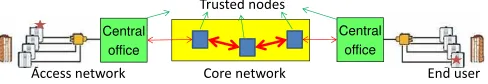
[image:2.612.317.561.162.204.2]Trusted nodes
Fig. 1: Trusted-node architecture for emerging quantum networks. The end users may be connected to the core network via passive optical networks. In order to generate a secret key between two end users, one must first generate a key between any two neighboring nodes along their connecting path. The key generated between the end user and its corresponding central office can then be encrypted and securely relayed node by node until it reaches the other party. Note that the internal links (thicker lines) must carry a higher traffic.
multiplexing (OFDM) techniques [8]–[13] and partly modify their setups in order to obtain spectrally efficient high-rate OFDM-QKD schemes.
QKD enables secure key exchange without relying on computational complexity. This is in contrast with existing techniques for key exchange, e.g., the RSA protocol [14], whose security is at risk with the advancement of technology [15]. In that sense, QKD provides a future-proof method of secure communications. The first proposed QKD protocol by Bennett and Brassard in 1984 (BB84) [7] relied on the polarization encoding of single photons. Since then new pro-tocols and encoding schemes have emerged and QKD has seen field demonstrations along with conventional telecom channels [2], [16]–[18]. Recent demonstrations cover distances over 250 km [19] and with nearly 50 users. The next step for QKD development will focus on extending the reach of the system and the number of users QKD networks can support.
Quantum networks are facing several challenges before their full implementation. One key requirement is their integra-tion with existing and future classical optical communicaintegra-tion networks [6], [20]. This implies the need for new quantum friendly standards for optical networks. That will include devising proper mechanisms by which weak quantum signals can be separated from classical channels [18], [21]. Multiple-access techniques are also needed to enable interference-free access to different quantum users [3], [22]. Eventually, QKD systems must improve their performance in terms of rate-versus-distance behavior and cost.
One feasible approach to long-distance QKD is based on trusted-node quantum networks. With current technology, we are able to generate secret keys at a rate on the order of Mb/s at 50 km of distance [18]. By cascading several of such links, as shown in Fig. 1,and trusting all intermediate nodes, one, in principle, can exchange secret keys at any distance by first generating secret keys between neighboring nodes and then relaying the initial key, in an encrypted way, to the other party. The main requirement for this approach is to trust all nodes in between the two end users. While this assumption may
be acceptable for the first generation of quantum networks, it can be removed in future generations by relying on quantum repeater setups at the core network [23].
In trusted-node networks, the internal nodes in the core network are expected to have a high traffic of key exchange as they are providing service to a large number of end users. It is important then to generate a large number of secret key bits per allocated wavelength to each quantum channel over these core links. One possible approach is to use non-binary signalings to send more key bits per transmitted quantum state [24]. In addition to this, we should think how most efficiently we can use the available bandwidth per allocated wavelength, especially with reference to QKD systems that rely on dense wavelength division multiplexing (DWDM) techniques [6]. Our proposed solution here relies on one of the most spectrally efficient methods in classical communications, i.e., OFDM. OFDM relies on the full orthogonality of its subcarriers to multiplex multiple channels. This full orthogonality is essential in QKD applications [3], [25], in order to minimize the interference from other classical and quantum users. In our case, each subcarrier represents a QKD channel between two core nodes. The total key generation rate between these two nodes is then expected to increase linearly by the number of subcarriers. Moreover, OFDM is compatible with non-binary signaling techniques, and that would enable us to take the maximum benefit from the available bandwidth. Finally, by using a multiplexing technique, multiple service providers can use the capacity of the core network without trusting each other. Note that the OFDM-QKD can be modified to be used as a multiple-access technique in multi-user QKD setups. In this paper, we focus on the multiplexing aspect with the objective of increasing the rate at the core of QKD networks.
Being an optical system, QKD can be merged best with OFDM if all-optical OFDM encoders and decoders are used. Here, we consider two possible implementations for the all-optical OFDM transmitter. In the first approach, the OFDM subcarriers are generated directly by a bank of frequency offset locked laser sources or an optical comb generator [8]–[10]. After encoding the subcarriers, an optical coupler combines them to generate the OFDM signal. The second approach uses the optical inverse discrete Fourier transform (OIDFT) circuit to generate the OFDM signal [10]–[13]. Short pulses are fed into the OIDFT circuit following the QKD encoding stage. Both these approaches rely on real-time optical discrete Fourier transform (ODFT) at their receivers. Conventional passive implementations of ODFT turn out to be too lossy to be useful for our main objective of increasing the rate. In our work, we show how the ODFT circuit can be modified to be effective for QKD applications.
Different QKD protocols can be used in our proposed OFDM-QKD setups. Here, we focus on the decoy-state variant of the BB84 protocol [26]. The decoy-state technique allows us to use weak laser pulses, rather than ideal single-photon sources as originally proposed in [7], and that would simplify the encoding equipment of QKD. In order to obtain immunity against the photon-number splitting attacks, in the decoy-state protocol, for every transmitted QKD pulse, the sender has to randomly choose its intensity from a set of available
intensities, where one of which corresponds to the main signal, and the rest to decoy states. In practice, it is often sufficient to use only two decoy states [27], although, in this paper, for analytical convenience, we assume infinitely many decoy states are used. Our proposed setups are compatible with other QKD protocols, such as continuous-variable or distributed-phase QKD protocols [28]. The detailed analysis of the latter systems is, however, beyond the scope of this paper.
Both optical OFDM and QKD are advanced technologies. It is interesting to see how drawbacks in one system would trans-late into the other. While some of the drawbacks with OFDM may directly affect our OFDM-QKD system, there are certain issues that are less of a problem in a QKD setup. For instance, one known OFDM problem in the classical domain is its high peak-to-average power ratio, which makes it susceptible to distortions due to nonlinearity effects [29], [30]. Fortunately, for QKD applications, nonlinearity is not necessarily a major issue because the QKD transmitted signals are low power. Nevertheless, the common OFDM-related imperfections such as time misalignment [31]–[33], phase noise introduced by the lasers [30], [34], [35], and frequency offsets between the transmitter and the receiver carriers (in the case of applying a local oscillator at the receiver) [30], [34] can potentially influence the orthogonality between subchannels, and subse-quently affect the performance of OFDM-QKD systems. In this paper, we specifically consider the degrading effects due to time misalignmnet, which is the major source of error in the most promising setup we propose here.
Finally, it is interesting to note that, while one of the key advantages of OFDM in the microwave domain is its reliance on digital signal processing, OFDM-QKD setups may less benefit from this feature. At the receiver side, any measurement on the OFDM signal before the QKD decoders could alter the transmitted states and result in errors. That is why it is important to have a fully optical setup for OFDM decoders. At the transmitter side, an optical OFDM setup would, in principle, allow multiple users to encode their key bits without trusting each other. This cannot necessarily be achieved if we first generate the OFDM signal electronically and then convert it to an optical signal. That said, there will be much room for improvement in future work, while, in this work, we assess the possibility of OFDM-QKD systems.
The rest of the paper is organized as follows. In the next section, we propose two OFDM-QKD schemes and describe their principles of operation. In Sec. III, the proposed OFDM-QKD schemes are analyzed from a quantum mechanical perspective. The analysis of secret key generation rate is presented in Sec. IV, in which we particularly focus on time misalignment issues within the OFDM system. We propose an optimal gating solution to maximize the key rate. Some numerical results are then presented in Sec. V. We conclude the paper in Sec. VI.
II. SystemDescription
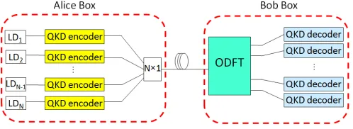
Fig. 2: QKD over an OFDM link. The QKD encoded optical pulses are mul-tiplexed by an all-optical OFDM encoder. At the receiver, the corresponding OFDM decoder followed by QKD decoders are used to generate secret keys.
that carry the information about the encoded key bits in each subchannel. The resulting optical pulses are fed simultaneously into the OFDM encoder to be multiplexed. At the receiver, the OFDM decoder followed by essential QKD decoding modules can be used to complete the QKD protocol. The key part in the OFDM decoder is an ODFT circuit, which effectively separates the subchannels.
In this paper, we assume that the QKD encoders perform phase encoding using decoy-state techniques [26]. Based on the phase-encoded BB84 protocol, Alice chooses her phase valueφA from one of the bases{0, π}or {π/2,3π/2}. The two phase values in each basis correspond to bits 0 and 1. As shown in Fig. 3, an optical pulse sent by Alice passes through a Mach-Zehnder interferometer (MZI). The output is two non-overlapping successive pulses, denoted byrands, of duration
T with a relative phase corresponding to the chosen basis and the transmitted key bit. The QKD decoding includes Bob’s selection of his measurement basis by choosing the phaseφB∈
{0, π/2}randomly in one arm of his MZI and the detection of the output signal. In the following, we describe two OFDM-QKD setups based on the proposed schemes for all-optical OFDM.
A. Scheme I
[image:4.612.331.546.202.276.2]Figure 4 depicts the OFDM-QKD system that relies on directly generated subcarriers. At the transmitter, a bank of frequency offset locked laser diodes generate the input optical pulses to N QKD encoders. These pulses are individually phase randomized, as required by the decoy-state protocol [36], and then go through a bank of encoders as in Fig. 3. Because the information is encoded in the phase difference, these overall random phases do not change the encoded bits. The same holds for the possible phase noise of the lasers so long as their phase is constant during the transmission of each bit. In our forthcoming analysis, we account for possible relative phase distortions between r and s pulses in Fig. 3. The outputs of the QKD encoders are then combined to form the OFDM signal. If we trust all the elements in the Alice box of Fig. 4, we can adjust the transmitted power such that
Fig. 3: Phase encoded QKD. Alice encodes her key bits by choosing a phase valueφA ∈ {0, π/2, π,3π/2}. Each optical pulse passes through the MZI and
produces two output pulses with the relative phaseφA. On the Bob’s side, a
similar MZI is used to recombinerandsmodes, followed by photodetection.
Fig. 4: OFDM-QKD using directly generated subcarriers. The optical pulses, generated byN frequency offset-locked laser diodes, are fed into the QKD encoders. At the receiver, an ODFT circuit is required to separate the subcarriers.
Gate Interval
T/4
T/4 T/2
0
/2
0
(a) (b)
ˆ( )
x t
0
ˆ b ( )t
1
ˆ b ( )t
2
ˆ
b ( )t yˆ3( )t
1
ˆ( )
y t
2( )
ˆ t y
0( )
ˆ t y
Fig. 5: (a) The passive ODFT circuit for N = 4. The circuit consists of three MZIs with corresponding delays and phase shifts. (b) Shifted replicas of the input OFDM signal for N = 4. The shift values for N = 4 are {0,T/4,T/2,3T/4}. The time slot, in which all these copies overlap, is extracted by the time gating operation.
it is at the output of the combiner that each subchannel has the right intensity for its corresponding pulse. This will allow us to neglect the losses in the encoder box, as we assume in this paper. At the receiver, ODFT is used to demultiplex the subcarriers. To comply with the OFDM orthogonality condition, in Scheme I, the pulse width is T =1/∆f, where ∆f is the frequency separation of the subcarriers.
To illustrate the principles of this scheme, consider the clas-sical case, where the OFDM signal is generated by combining classical subchannels as follows:
x(t)= N−1
X
k=0
akejωkt, 0<t<T, (1)
whereakis the complex amplitude of thekth subchannel with frequencyωk=ω0+2πk∆f for a nominal channel frequency ω0. The ODFT circuit, at the decoder, will then separate different subcarriers and generate the following output signals:
ym(t)= 1
N
N−1
X
n=0
x(t−nTc)ej2πnm/N, m=0,1, ...,N−1, (2)
whereTc,T/N. With the assumption of T =1/∆f, we can conclude from (1) and (2) that
ym(t)= N−1
X
k=0
akejωkt( 1
N
N−1
X
n=0
ej2πn(m−k)/N). (3)
The term in the brackets is nonzero only ifk=m, which leads to themth subcarrier extraction.
[image:4.612.52.297.650.693.2]Fig. 6: OFDM-QKD using OIDFT circuit. A train of short pulses generated by an MLL is split into N paths. The OFDM symbol is generated by multiplexing the output pulses of the QKD encoders by the OIDFT circuit. The OFDM symbol consists of a series of pulses, each a superposition of pulses from different inputs. At the receiver, an ODFT circuit demultiplexes the subcarriers.
method of realizing DFT, known as fast Fourier transform (FFT), by means of delays, couplers, and phase shifters. Each output port of the ODFT circuit is a weighted sum of shifted replicas of the input as required by (2). It will then provide us with a real-time DFT operation once all shifted replicas of the input overlap, as shown in Fig. 5(b). That would require a time gating operation [8], [9], which can be implemented by electro-absorption modulators (EAM), or simply by time-gating the single-photon detectors used in the QKD decoders. Time misalignment can then be a major source of error in such a scheme. The quantum operation of the ODFT circuit is discussed in more detail Sec. III.
B. Scheme II
Figure 6 shows an alternative setup for the OFDM-QKD system. Here, the output of a pulsed laser source, e.g., a mode-locked laser (MLL), is split into several paths by an optical splitter. The pulses should be short enough to cover the spectrum of all the subcarriers in the OFDM symbol. Here, we assume that the pulse width is slightly lower thanTc. Similar to Scheme I, each short pulse, after splitting, is fed into QKD encoders to produce successive pulses rand s. Each of these pulses will then go through an OIDFT circuit generating N
short pulses within an OFDM symbol duration T. The delay in the MZI of Fig. 3 is assumed to be greater thanT.
The required OIDFT can be implemented by a structure similar to the ODFT. For instance, the circuit in Fig. 5(a), for the special case of N = 4, can be employed for OIDFT as well. In the case of OIDFT, the input pulses (denoted by y
components) enter from the right hand side of Fig. 5(a) and the output will be the signal labeled by ˆx(t). Assuming that the
ypulses are synchronous, in each OFDM symbol, the output signalxconsists of four pulses apart by multiples ofTcwithin a T-long frame. Each of the latter pulses are a combination of all input pulses, as shown in Fig. 6.
More generally, in the classical case, the generated OFDM amplitude at any carrier frequency ω is given by
x(t)= N−1
X
k=0 N−1
X
l=0
Akp(t−lTc)ej2πkl/N, (4)
where p(t) represents the shape of the initial laser pulse and
Ak is the complex amplitude of thekth subchannel. Note that in Fig. 6, subchannels are separated spatially at the input to
OIDFT. At the receiver, the ODFT operation in (2) shifts each of the pulses within an OFDM symbol and combines them together to generate
ym(t)= 1
N2 N−1
X
n=0 N−1
X
k=0 N−1
X
l=0
akp(t−(n+l)Tc)ej2π(kl+nm)/N, (5)
form∈ {0,1, ...,N−1}. In a real-time implementation, only at
n+l=N−1, all relevant input pulses are added together at whichym(t) reduces to
zm(t)= N−1
X
k=0
Ak
Np(t−(N−1)Tc)e
j2πk(N−1)/N (1
N
N−1
X
n=0
ej2πn(m−k)/N).
(6) Here again, the term in the brackets is zero for k,m, which implies that, up to a known overall phase factor, the original information in Am can be recovered at themth output port of the ODFT circuit of Fig. 6.
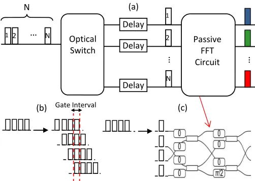
For the receiver of Scheme II, we have two options. We can either use the passive OFDM decoder used in Scheme I, or, alternatively, the active structure shown in Fig. 7(a). The main advantage of the latter is to remove the inherent loss in the passive OFDM decoder. To better explain the loss effect in the passive decoder, consider a sequence ofN pulses at the input x(t) of Fig. 5(a), and let us look at the output signals. In this case, each input pulse has four paths to take, with different delays and phase shifts, to reach to the output ports of Fig. 5(a). In other words, for each input pulse, there will be four output pulses at each of the decoder’s four output ports; see Fig. 7(b). Only one out of these four output pulses has the right amount of delay and phase shift to be used for our ODFT operation, and that is why time gating is required. The inevitable drawback of this approach is that the other three pulses, and the power therein, will remain unused and that will contribute to a maximum total efficiency of 1/N for a passive decoder as in Fig. 5(a). To overcome this drawback, our proposed OFDM decoder in Fig. 7(a) employs an optical switch along with proper delays, instead of a passive circuit, to perform the serial to parallel conversion. As shown in Fig. 7(c), this way there will be no extra pulses to be discarded, and the ODFT process can be implemented by a passive N-by-N
circuit, of a star topology but with phase shifters along each internal path, with no fundamental overall loss [8], [37].
… …
…
1 2 N Optical
Switch N Delay Delay Delay Passive FFT Circuit (c) (b) (a) Gate Interval 1 2 N
Fig. 7: (a) ProposedactiveODFT circuit. By employing an optical switch instead of a power splitter, the loss of time gating is eliminated. (b) Passive approach to serial-to-parallel conversion forN=4. Some pulses are generated and then discarded during the time gating process. (c) Active approach to serial-to-parallel conversion forN=4 followed by the FFT circuit [8].
will introduce some additional insertion loss. The latter, within our practical regime of interest, is shown to be less than 2 dB for ultrafast optical switches and will be accounted for in our numerical analysis [38]. Optical switches may also have nonzero extinction ratios, because of which some power leaks to other undesired output ports. This is a minor problem for the decoder of Fig. 7(a), because the input pulses to the switch are non-overlapping in time. By using time gating and proper delay lines, the leaked power to other ports should not appear in the same time slot that time gating is taking place, hence has negligible effect on system performance.
III. QuantumAnalysis
In this section, we analyze the OFDM-QKD systems pro-posed in Sec. II from a quantum mechanical perspective. We choose the Heisenberg picture for our analysis. In two steps, we first concentrate on the operation of the system corresponding to each of the two pulses r and s in Fig. 3, and then we combine the results to find the output operators in QKD decoding modules.
A. Scheme I
In the Heisenberg picture, the output operator of the Alice box in Fig. 4 can be expressed as
ˆ
x(t)= N−1
X
k=0 ˆ
akejωkt, 0<t<T, (7)
where ˆak is the annihilation operator corresponding to the mode representing the kth subcarrier. For the rest of this sec-tion, we neglect the path loss effect, which will be considered when we calculate the secret key generation rate. We then focus on the receiver setup assuming that at its input the signal
ˆ
x(t) is received.
For simplicity, let us first consider the special case ofN=4. As shown in Fig. 5, the ODFT circuit, in this case, is imple-mented by three MZIs. The operators ˆb0(t) = PkN=−01bˆ0kejωkt,
ˆ
b1(t) =PkN=−01bˆ1kejωkt and ˆb2(t) = PNk=−01bˆ2kejωkt represent the vacuum fluctuations of the unused ports of the MZIs’ beam splitters corresponding to all existing frequency modes of the system. For a center frequency,ω, the transformation matrices of the three MZIs in Fig. 5 are given by
Bω,1= 1 2 1 j j 1 ! 1 0
0 e−j(ωT2)
!
1 j j 1
!
, (8)
for the MZI on the left,
Bω,2= 1 2 1 j j 1 ! 1 0
0 e−j(ωT 4) ! 1 j j 1 ! , (9)
for the one on top right, and
Bω,3 = 1 2 1 j j 1 ! 1 0
0 je−j(ωT 4) ! 1 j j 1 ! , (10)
for the one on bottom right of Fig. 5(a). Applying the above transformations to modek, we obtain
ˆ
a′k(t) ˆ
b′
k(t) !
=Bωk,1
ˆ
ak(t) ˆ
b0k(t) !
, (11)
ˆ
y0,k(t) ˆ
y1,k(t) !
=Bωk,2
ˆ
a′
k(t) ˆ
b1k(t) !
, (12)
ˆ
y2,k(t) ˆ
y3,k(t) !
=Bωk,3
ˆ
b′
k(t) ˆ
b2k(t) !
. (13)
The output operator for output portmin Fig. 5 is then given by
ˆ
ym(t)= 3
X
k=0 ˆ
ym,k(t), m=0,1,2,3. (14)
Note that the above operations are all linear. Based on the superposition principle, we can split each output ˆym(t) to two parts. The first part is the output obtained by neglecting the vaccum operators, and the other part is a linear combination of all vacuum operators. More generally, it can be concluded that the output of such an ODFT circuit, neglecting the vacuum operators, can be expressed as a function of ˆx(t), as follows:
ˆ
Xm(t)= 1
N
N−1
X
n=0 ˆ
x(t−nTc)ej2πnm/N, m=0, . . . ,N−1, (15)
which is similar in form to (2) for the classical case. Substi-tuting (7) into (15) and applying the orthogonality condition, ∆f = T1, we obtain
ˆ
Xm(t)= N−1
X
k=0 ˆ
akej2π(f0+k∆f)t( 1
N
N−1
X
n=0
ej2πn(m−k)/N). (16)
Note that the term in the brackets is nonzero only if k=m. We then obtain
ˆ
ym(t)=Aaˆm(t)+ N−2
X
i=0 N−1
X
k=0
βikbˆik(t), m=0, . . . ,N−1, (17)
[image:6.612.49.300.53.231.2]copies of the OFDM signal overlap. The signal corresponding to this overlapping time slot will eventually be detected by the photodetectors in the receiver module.
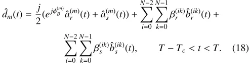
With the phase encoding QKD protocol, the two successive pulses r and s for channel m, represented by ˆa(rm) and ˆa
[image:7.612.54.301.160.241.2](m) s , respectively, will be recombined at the receiver’s MZI in Fig. 3. The output operator corresponding to the recombined pulsed in Fig. 3 for the mth output is then given by
ˆ
dm(t)=
j
2(e jφ(m)B
ˆ
ar(m)(t)+aˆ(sm)(t))+ N−2
X
i=0 N−1
X
k=0
β(rik)bˆ(rik)(t)+
N−2
X
i=0 N−1
X
k=0 β(sik)bˆ
(ik)
s (t), T−Tc<t<T. (18)
B. Scheme II
To start our analysis in this scheme, we denote the annihila-tion operator corresponding to the spatial mode at the output of the kth QKD encoder by ˆak. We assume that an OIDFT circuit similar to the one depicted in Fig. 5(a) for N=4, yet in the reverse direction, is used at the transmitter. Then, we can obtain the output operator of the Alice box by applying the transformation matrix of each MZI. It can be concluded that the output operator of the Alice box is given by
ˆ
x(t)= 1
N
N−1
X
l=0 ˆ
clp(t−lTc), (19)
where ˆcl = PNk=−01aˆkej2πkl/N is the lth temporal mode at the output of the OIDFT circuit. Note that the coefficient 1/N in (19) is not necessarily a source of loss, so long as the average number of photons per pulse at the output of the transmitter meets the requirements of the decoy-state protcol. That is we can compensate for the internal loss at the transmitter by tuning the intensity of the incoming light. In our following analysis, this factor 1/N has been neglected. With a passive OFDM decoder similar to that of Scheme I at the receiver, the analysis presented in the previous subsection can be useful here as well, except that here we deal with temporal modes. Substituting (19) in (15) and simplifying the equations at
n+l=N−1, we can express each output of the ODFT circuit as
ˆ
ym(t)=[ˆamej2πm(N−1)/N+ N−2
X
i=0 N−1
X
k=0 βikbˆik]
×p(t−T +Tc), m=0, . . . ,N−1. (20)
The coefficient ej2πm(N−1)/N is a constant phase term that can be absorbed in ˆam in the above equation.
Finally, the output operator obtained by the recombination of the pulses r and s by means of the receiver’s MZI, ˆdm(t), is given by
ˆ
dm(t)=[
j
2(e jφ(m)B
ˆ
a(rm)+aˆ(sm))+ N−2
X
i=0 N−1
X
k=0
β(rik)bˆ(rik)+
N−2
X
i=0 N−1
X
k=0
β(sik)bˆ(sik)]×p(t−T+Tc). (21)
Another option for the receiver in this scheme is the structure we proposed in Fig. 7(a). For this active decoder, (21) is multipled by an additional factor √N. Furthermore, no vacuum components would appear because the beam splitters in the FFT circuit do not have any unused ports [8].
IV. KeyRateAnalysis
This section presents an analysis of the secret key generation rate for the proposed OFDM-QKD schemes. We assume that the efficient decoy-state BB84 protocol is employed in the QKD setup [39], [40]. The average number of photons per QKD channel is given by µ, for the main signal state, and it is calculated at the output of the Alice box. The secret key generation rate per transmitted pulse, in the limit of an infinitely long key, is lower bounded by max[0,P(Y0)], where
P(Y0)=Q1(1−h(e1))−f Qµh(Eµ), (22)
andh(p)=−plog2p−(1−p)log2(1−p) is the binary entropy function with f being the error correction inefficiency. The overall gain, the QBER, the gain of a single photon state and the error rate of a single photon state are, respectively, given by [3]
Qµ=1−(1−Y0)e−ηµ,Eµ=(Y0/2+ed(1−e−ηµ))/Qµ,
Q1=Y1µe−ηµ,e1=(Y0/2+edη)/Y1. (23)
Equations (22)-(23) provide an estimate to the generated key rate when infinitely many decoy states are in use and no eavesdropper is present. In the above equations, Y1 = (1−η)Y0 +η is the yield of a single photon state and Y0 is the probability of any detector clicks without having any transmitted photons from the corresponding QKD encoder. Furthermore, ed represents the probability of phase stability errors, betweenrandspulses, and the total transmissivity of the link is given by
η=ηgηdηins10−αL/10, (24)
where ηd is the quantum efficiency of the photodetectors, α is the channel loss factor in dB per unit of length and ηins represents any additional insertion loss in the link. Here, ηg represents the additional loss due to the OFDM decoding scheme. For instance, in Scheme I, with gate interval ofTc, the parameterηg equals 1/N in the ideal case. For Scheme II, and the active decoder of Fig. 7(a),ηg is ideally one.
We calculate the parameters in (23) by finding the prob-abilities of interest once the QKD measurements are done. For instance, the measurement operator for the representative photodetector in Fig. 3 is given by
ˆ
M =
Z
gate inteval ˆ
dm†(t) ˆdm(t)dt, (25)
from which one can obtain key rate parameters. In the analysis of the key generation rate, the terms containing vacuum states will not contribute to the key rate parameters, and that simplifies the calculations.
TABLE I: Nominal values for system parameters
Parameter Value
Average number of photons per signal pulse 0.48
Quantum Efficiency 0.3
Total insertion and path loss,ηins10−αL/10 10 dB Receiver dark count rate,γdc 1E-7 ns−1
Error correction inefficiency, f 1.22
Phase stability error,ed 0.005
Laser pulse repetition interval,Ts 210 ps
OFDM symbol duration,T 100 ps
Number of subcarriers,N 4, 8, 16
system performance. As explained before, we specifically consider time misalignment issues, which are known to be critical in all-optical OFDM systems. In OFDM, the time alignment of the optical subchannels is critical, due to its effect on their orthogonality. Furthermore, the time gating at the receiver should be synchronized with the transmitted pulses to extract the correct time slot. In our OFDM-QKD setups, nonidentical QKD encoders or some errors in time-gating synchronization may introduce time misalignment.
In our work, we have found the key generation rate of our proposed OFDM-QKD schemes in the presence of time misalignment issues. It turns out that they cause two problems. First, they generate some inter-channel crosstalk, denoted by
pxtalk, which adds to the background noise, and, second, they slightly reduce the transmissivity factor ηg. One can reduce the crosstalk noise by reducing the width of the gate interval, but, by doing so, ηg would further be reduced, as we have to leave out some of the desired signal components as well. That would imply the existence of an optimal gate width at which the total secret key rate ROFDM is maximized, where
ROFDM =max[NP(YOFDM)/Ts,0], (26)
and
YOFDM =1−(1−(pdc+pxtalk))2. (27)
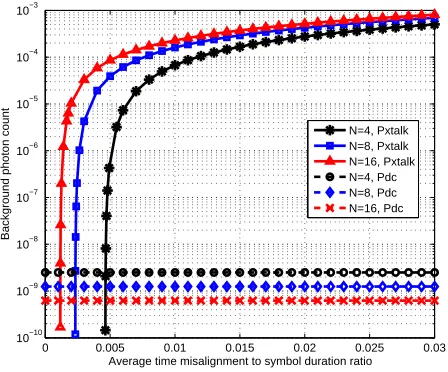
Here,Ts represents the repetition period of the QKD protocol andpdc=γdcTg, whereγdcandTgare the photodetectors’ dark count rate and the gate interval, respectively. In Appendix A, we have derived all the required terms for calculating the above key rate as a function of the average time misalignment E{|τk|}, whereτk’s are i.i.d random variables representing the time misalignment of the kth channel with respect to the gate interval, and δ,(Tc−Tp)/2, where Tp is the pulse width in Scheme II. In the following, we present some of our numerical findings for a selected set of parameter values.
V. NumericalResults
In this section, we investigate the performance of the proposed OFDM-QKD schemes by considering the following cases: Scheme I and Scheme II with passive OFDM decoders, and Scheme II with the active OFDM decoder of Fig. 7(a). In order to evaluate the effect of time misalignment on the performance of each case, each subcarrier is assumed to have a time misalignment with uniform distribution,τk∼U(−a,a), where a < Tc is an arbitrary constant. We then find the optimal gate width that maximizes the key rate. The nominal values used for the system parameters are listed in Table
0 0.005 0.01 0.015 0.02 0.025 0.03
10−10 10−9 10−8 10−7 10−6 10−5 10−4 10−3
Average time misalignment to symbol duration ratio
Background
photon
count N=4, Pxtalk N=8, Pxtalk N=16, Pxtalk N=4, Pdc N=8, Pdc N=16, Pdc
Fig. 8: Background photon count probability componentspdcandpxtalkversus E{|τk|}/T for Scheme II with active OFDM decoder, for different values of
N.
I. These parameters are chosen in accordance to practical considerations. With the chosen OFDM symbol duration, the subchannel frequency separation,∆f, has to be 10 GHz, which has been used in several all-optical OFDM experiments [10], [41]. The pulse width, Tp, in Scheme II should be less than
Tc=T/N. Here, we assume that the ratioδ/Tp in this scheme is equal to 0.04.
[image:8.612.72.278.63.161.2]In order to see the importance of the time misalignment issue, we first look at its induced cross talk contribution as compared to the dark count component. Figure 8 compares the two elements of the background noise, i.e., pdc and pxtalk, versus a normalized measure of misalignment, E{|τk|}/T, in the special case of Scheme II with active decoders. A similar overall behavior is observed for other schemes as well. It is clear that while the cross talk is negligible for low values of time misalignment, it becomes the major source of noise in our OFDM-QKD setups. We next consider the effect of time misalignment on each of the proposed setups.
Figure 9 shows the effect of time misalignment on the total secret key generation rate, ROFDM, of Scheme I with and without optimal time gating. In the latter case, the gate width is a constant Tc. It can be seen that by optimizing the gate interval the secret key rate significantly improves. It will, however, barely surpass the performance of a single-carrier link, shown on top of Fig. 9, run at the same clock rate as the OFDM system. The main reason for this is the loss factorNdue to the time gating, which results in a reduced key rate per carrier. Moreover, Fig. 9 shows that a system with a larger number of subcarriers, N, is more susceptible to time misalignment errors. This has to do with the interplay between
pxtalk and ηg, where the latter turns out to be the dominant factor. In short, no rate advantage is obtained by Scheme I. It, nevertheless, can be used as a multiplexing tool for sharing the infrastructure between multiple service providers.
0 0.005 0.01 0.015 0.02 0.025 0.03 2
2.5 3 3.5 4 4.5 5 5.5x 10
7
Average time misalignment to symbol duration ratio
Secret
key
generation
rate
(b/s)
[image:9.612.64.281.56.248.2]N=4 N=8 N=16 N=4, optimal gate N=8, optimal gate DWDM (per channel)
Fig. 9: Secret key generation rate versus E{|τk|}/T for Scheme I and its
optimal gate version, for different values ofN.
0 0.005 0.01 0.015 0.02 0.025 0.03
2 2.5 3 3.5 4 4.5 5 5.5x 10
7
Average time misalignment to symbol duration ratio
Secret
key
generation
rate
(b/s)
N=4 N=8 N=16 N=4, optimal gate N=8, optimal gate DWDM (per channel)
Fig. 10: Secret key generation rate versus E{|τk|}/Tfor Scheme II with passive
OFDM decoder and its optimal gate version, for different values ofN. The parameterδ/Tpis chosen to be 0.04.
applying the optimal gate interval results in an enhancement in the secret key rate. Yet, no improvement, as compared to the DWDM-QKD system, is observed in the overall key rate by increasing N, which is mainly due to the inherent loss in the passive structure of the OFDM decoder.
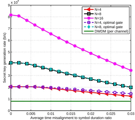
The secret key generation rate of Scheme II with the pro-posed active OFDM decoder is depicted in Fig. 11. It can be seen that by multiplexing more subchannels in the system the secret key rate increases. This increase is initially linear with the number of subchannels, but once the time misalignment kicks in the key rate also correspondingly drops. Nevertheless, it always stays above that of the single DWDM-QKD channel depicted in the bottom of the figure. In fairness to the DWDM system, we have accounted for 2 dB of additional insertion loss for the optical switch in the OFDM-QKD system. The DWDM curve uses 100-ps-long pulses. Under these conditions, for
N = 16, and at a normalized average time misalignment of 0.02, we are doing almost 6 times better than the single carrier link. That would demonstrate the prospect of using OFDM techniques at the core of QKD networks.
0 0.005 0.01 0.015 0.02 0.025 0.03
0 1 2 3 4 5 6 7 8 9x 10
8
Average time misalignment to symbol duration ratio
Secret
key
generation
rate
(b/s)
[image:9.612.327.546.123.317.2]N=4 N=8 N=16 N=4, optimal gate N=8, optimal gate DWDM (per channel)
Fig. 11: Secret key generation rate versus E{|τk|}/Tfor Scheme II with active
OFDM decoder and its optimal gate version, for different values of N. The parameterδ/Tpis chosen to be 0.04.
In addition to the total key rate, we also look at the spectral efficiency of each scheme, S, defined by the ratio of the secret key generation rate and the allocated bandwidth. In the case of a DWDM link with channel spacing of 50 GHz, in Fig. 11,S =0.16%. For the OFDM-QKD systems, assuming that the allocated bandwidth is given by N/T, S has a peak value of 0.5%, which is three times higher than that of the DWDM system. Once time misalignment kicks in, the OFDM-QKD systems with lower values ofN are favored as they are less susceptible to such errors. Overall, it can be seen that by multiplexing 4–8 OFDM subcarriers, one can outperform DWDM-QKD systems both in terms of the total key rate and the spectral efficiency in practical regimes of operation [32].
VI. Conclusions
[image:9.612.64.280.302.488.2]could eliminate the inherent loss in passive decoders. We remark that, in the case of active decoders, ultrafast switches with a transition time on the order of picoseconds may be required. This is due to the short time separation of pulses within an OFDM symbol [38], [42]. This may add to the cost and complexity of the system. Nevertheless, we showed that, using our proposed active decoders, we could outperform the alternative DWDM-QKD systems in terms of the total key rate and spectral efficiency. This implies that OFDM-QKD can provide a high-rate spectrally efficient method of key exchange at the core of trusted-node QKD networks.
AppendixA
OFDM-QKDwith misalignment errors
In this appendix, we analyze the operation of our proposed OFDM-QKD setups in the presence of time misalignment.
A. Scheme I
We start our analysis by assuming that each subcarrier has a time misalignment τk, 0 < |τk| < Tc, with respect to the time gating interval. Without loss of generality, we assume that 0 ≤τk <Tc (both cases ofτk >0 and τk <0 have the same effect). Figure 12(a) shows the shifted copies of thekth
subcarrier pulse in the presence of time misalignment τk. As can be seen in the figure, the shifted copies does not overlap completely in the gate interval, which leads to different summation results in two distinct time intervals, as follows:
t∈(T −Tc,T−Tc+τk)⇒Xˆm(t)= ( 1
Naˆk(t) k,m N−1
N aˆm(t) k=m (28)
t∈(T −Tc+τk,T)⇒Xˆm(t)= (
0 k,m
ˆ
am(t) k=m .(29)
As a consequence, equation (18) is modified to
ˆ
dm(t)=
j
2{
N−1
N (e
jφ(m)B
ˆ
ar(m)(t)+aˆ(sm)(t))|t∈(T−Tc,T−Tc+τm)+
(ejφ(m)B aˆ(m)
r (t)+aˆ (m)
s (t))|t∈(T−Tc+τm,T)+
1
N
X
k,m
(ejφ(k)Baˆ(k)
r (t)+aˆ (k)
s (t))|t∈(T−Tc,T−Tc+τk)}, (30)
with the third term representing the inter-subcarrier crosstalk on themthsubcarrier. Here, we neglected the vacuum operators due to their elimination once we apply the measurement operator. The background count due to this crosstalk may influence the performance of the system, as we will show in the following.
Defining ˆgk(t) , N1(ejφ
(k)
Baˆ(rk)(t)+aˆ(sk)(t)) with initial state |αir|αejφ
(k)
Ais, we can write
hgˆ†kgˆki= 2µ
N2(1+cos(φ (k) A −φ
k B))
τk
T. (31)
Here, µ = |α|2 and φ(Ak) is the relative phase produced by the QKD encoder of thekth subcarrier. We then calculate the expected value of (31) as a function of (φ(Ak) −φ(Bk)), which results in
E(φ(k) A−φ
k B){hˆ
g†kgˆki}= 1
2E(φ(k)A−φ(k)B){hgˆ
†
kgˆki|basis={0, π}}+ 1
2E(φ(k)A−φ(k)B){hgˆ
†
kgˆki|basis={π/2,3π/2}}= 2µτk
N2T. (32)
Note that cross terms between any two different subcarriers also appear in the hdˆ†mdˆmi. Here, we assume that the laser sources have independent phases. In this case, the phase differ-ence corresponding to any cross term has uniform distribution on the interval [−π, π]. These terms are then eliminated due to their zero expected values. At this point, we generalize our result to include the case−Tc≤τk<0. Hence, equation (32) can be rewritten as
E(φ(k) A−φ
k B){hˆ
g†kgˆki}= 2µ|τk|
N2T . (33)
In the last step, the partial crosstalks due to each subcarrier are added to obtain the total crosstalk background count on themth subcarrier, denoted byp(m)
xtalk, as follows:
p(xtalkm) =η′ 2µ
N2T
X
k,m
E{|τk|}, (34)
whereη′is the transmissivity of the link, excluding the loss of time gating. Under the assumption that|τk|’s are i.i.d random variables, p(xtalkm) is independent of the subcarrier index. So, we can express the crosstalk background count per subcarrier as
pxtalk=η′
2µ(N−1)E{|τk|}
N2T . (35)
Such time misalignments change the loss factor in the time gating operation, ηg, due to the additional loss occurring in the interval (T−Tc,T−Tc+τm) in (30).ηg is then given by
ηg= 1
N −(
E{|τk|}
T )(1−( N−1
N )
2
). (36)
Now, let us reduce the gate interval byb from each side to reduce the crosstalk effect. It can be concluded from Fig. 12(a) that pxtalk=E{A}, where A is obtained by
A=
(
η′2µN(N2T−1)(|τk| −b) |τk| ≥b 0 |τk| ≤b
(37)
and pxtalk can be expressed as
pxtalk=η′
2µ(N−1)
N2T p(|τk| ≥b)(E{|τk|||τk| ≥b} −b). (38) Furtheremore,ηg=E{B}, where
B=
( 1 N−
2b T −
1 T(1−(
N−1 N )
2)((
|τk| −b) |τk| ≥b
0 0≤ |τk| ≤b
(39) and
ηg= 1
N −
2b T −
1
T(1−( N−1
N )
2
)p(|τk| ≥b)(E{|τk|||τk| ≥b} −b). (40)
B. Scheme II
As explained in Sec. II, two receiver structures can be applied for this scheme: the passive OFDM decoder used in Scheme I, and the active OFDM decoder, which exploits an optical switch. In this subsection, we derive the crosstalk background count for both receiver structures.
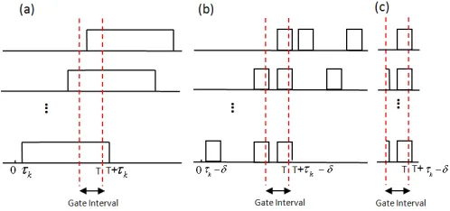
Fig. 12: Shifted copies of the signal corresponding to kth tributary in the
presence of the time misalignmentτk, for (a) Scheme I, (b) Scheme II with
passive OFDM decoder, (c) Scheme II with active OFDM decoder.
depicts the replicas of the pulse series corresponding to thekth
tributary. We denote the width of each pulse byTp. Following the same steps as in the previous subsection, we conclude that the output operator, ˆdm(t), for 0< τk< δis given by
ˆ
dm(t)=
j
2(e jφ(m)B
ˆ
a(rm)(t)+aˆ(sm)(t)), (41)
and for δ < τk<Tc we have
ˆ
dm(t) =
j
2{
N−1
N (e
jφ(m)B
ˆ
ar(m)(t)+aˆ(sm)(t))|t∈(T−Tc,T−Tc+τm−δ)
+ (ejφ(m)B aˆ(m)
r (t)+aˆ (m)
s (t))|t∈(T−Tc+τm+δ,T)
+ 1
N
X
k,m
(ejφ(m)B aˆ(k)
r (t)+aˆ (k)
s (t))|t∈(T−Tc,T−Tc+τk−δ)},(42)
where δ=(Tc−Tp)/2. From this equation we can conclude that in the case ofδ <|τk|<Tc, an inter-subcarrier crosstalk is introduced. We can then derive the background count of such crosstalk by applying the same strategy as in the previous subsection. The final result can be expressed as
pxtalk=η′
2µ(N−1)
N3T p
p(|τk| ≥δ)(E{|τk|||τk|> δ} −δ). (43)
Furthermore, the degrading effect of time misalignment onηg modifies this parameter to
ηg= 1
N −(
1
NTp
)(1−(N−1
N )
2
)p(|τk| ≥δ)(E{|τk|||τk|> δ} −δ).
(44) Now, we consider the narrowed gate case. If the gate interval is decreased by b from each side, we can conclude from Fig. 12(b) that pxtalk=E{A}, where
A=
η′2µ(N−1)
N3Tp (|τk| −b−δ) |τk| ≥b+δ 0 |τk| ≤b+δ
(45)
Hence, pxtalk can be written as
pxtalk=η′
2µ(N−1)
N3T p
p(|τk| ≥b+δ)(E{|τk|||τk| ≥b+δ} −(b+δ)).
(46) The loss factor ηg is also obtained by E{B}, where Bis given by
B=
1 N −
2b NTp −
1 NTp(1−(
N−1 N )
2
)((|τk| −(b+δ)) |τk| ≥b+δ 1
N −
|τk|+b−δ
NTp |b−δ| ≤ |τk| ≤b+δ
1 N−
2(b−δ)
NTp u(b−δ) 0≤ |τk| ≤ |b−δ|
(47)
whereu(.) is the step function. Hence,ηgcan be expressed as
ηg= 1
N − {(
2b NTp −
(b+δ)
NTp
(1−(N−1
N )
2
))p(|τk| ≥b+δ)+
1
NTp
(1−(N−1
N )
2
)p(|τk| ≥b+δ)(E{|τk|||τk| ≥b+δ})+
(b−δ)
NTp
p(|b−δ| ≤ |τk| ≤b+δ))+ 1
NTp
(p(|τk| ≥ |b−δ|)
(E{|τk|||τk| ≥ |b−δ|})−p(|τk| ≥b+δ)(E{|τk|||τk| ≥b+δ}))
−2(NTb−δ)
p
p(|τk|<b−δ)u(b−δ)} (48)
Next, we discuss the time misalignment issue in Scheme II with an active OFDM decoder. Figure 12(c) shows the pulse series of thekth tributary in the presence of time misalignment τk, 0 < |τk| < Tc, with respect to the switching time. Due to the elimination of the loss incurred by passive serial to parallel conversion, equations (41) and (42) are modified by a multiplicative factor √N. Hence, the parameters pxtalk andηg are, respectively, given by (43) and (44), multiplied by N.
References
[1] M. Peevet al., “The SECOQC quantum key distribution network in Vienna,”New J. Phys., vol. 11, p. 075001, 2009.
[2] M. Sasakiet al., “Field test of quantum key distribution in the Tokyo QKD Network,”Opt. Exp., vol. 19, no. 11, pp. 10 387–10 409, 2011. [3] M. Razavi, “Multiple-access quantum key distribution networks,”IEEE
Trans. Commun., vol. 60, no. 10, pp. 3071–3079, 2012.
[4] P. D. Townsend, “Quantum cryptography on multiuser optical fibre networks,”Nature, vol. 385, no. 6611, pp. 47–49, 1997.
[5] K.-I. Kitayama, M. Sasaki, S. Araki, M. Tsubokawa, A. Tomita, K. In-oue, K. Harasawa, Y. Nagasako, and A. Takada, “Security in photonic networks: threats and security enhancement,” Journal of Lightwave Technology, vol. 29, no. 21, pp. 3210–3222, 2011.
[6] A. Ciurana, J. Mart´ınez-Mateo, M. Peev, A. Poppe, N. Walenta, H. Zbinden, and V. Martin, “Quantum metropolitan optical network based on wavelength division multiplexing,” Optics express, vol. 22, no. 2, pp. 1576–1593, 2014.
[7] C. H. Bennett and G. Brassard, “Quantum cryptography: Public key distribution and coin tossing,” in Proceedings of IEEE International Conference on Computers, Systems, and Signal Processing. Bangalore, India: IEEE, New York, 1984, pp. 175–179.
[8] D. Hillerkuss, M. Winter, M. Teschke et al., “Simple all-optical FFT scheme enabling Tbit/s real-time signal processing,” Optics express, vol. 18, no. 9, pp. 9324–9340, 2010.
[9] D. Hillerkuss, R. Schmogrow, T. Schellingeret al., “26 Tbit/s line-rate super-channel transmission utilizing all-optical fast Fourier transform processing,”Nature Photonics, vol. 5, no. 6, pp. 364–371, 2011. [10] Z. Wang, K. S. Kravtsov, Y.-K. Huang, and P. R. Prucnal, “Optical
FFT/IFFT circuit realization using arrayed waveguide gratings and the applications in all-optical OFDM system,”Optics express, vol. 19, no. 5, pp. 4501–4512, 2011.
[11] S. Shimizu, G. Cincotti, and N. Wada, “Demonstration and performance investigation of all-optical OFDM systems based on arrayed waveguide gratings,”Optics express, vol. 20, no. 26, pp. B525–B534, 2012. [12] J. Schr¨oder, L. B. Du, J. Carpenter, B. J. Eggleton, and A. J. Lowery,
“All-optical OFDM with cyclic prefix insertion using flexible wavelength selective switch optical processing,”Journal of Lightwave Technology, vol. 32, no. 4, pp. 752–759, 2014.
[13] H. Chen, M. Chen, and S. Xie, “All-optical sampling orthogonal frequency-division multiplexing scheme for high-speed transmission system,”Lightwave Technology, Journal of, vol. 27, no. 21, pp. 4848– 4854, 2009.
[14] R. L. Rivest, A. Shamir, and L. Adleman, “A method for obtaining digital signatures and public-key cryptosystems,”Communications of the ACM, vol. 21, no. 2, pp. 120–126, 1978.
[image:11.612.313.569.69.188.2][16] D. Stuckiet al., “Long-term performance of the swissquantum quantum key distribution network in a field environment,”New Journal of Physics, vol. 13, no. 12, p. 3001, 2011.
[17] W. Chenet al., “Field experiment on a star type metropolitan quantum key distribution network,”IEEE Photon. Technol. Lett., vol. 21, no. 9, pp. 575–577, May 2009.
[18] K. A. Patelet al., “Coexistence of high-bit-rate quantum key distribution and data on optical fiber,”Phys. Rev. X, vol. 2, p. 041010, Nov. 2012. [19] S. Wanget al., “2 GHz clock quantum key distribution over 260 km of
standard telecom fiber,”Opt. Lett., vol. 37, no. 6, pp. 1008–1010, March 2012.
[20] W. Maeda, A. Tanaka, S. Takahashi, A. Tajima, and A. Tomita, “Tech-nologies for quantum key distribution networks integrated with optical communication networks,” Selected Topics in Quantum Electronics, IEEE Journal of, vol. 15, no. 6, pp. 1591–1601, 2009.
[21] I. Choi, R. J. Young, and P. D. Townsend, “Quantum information to the home,”New J. Phys., vol. 13, p. 063039, June 2011.
[22] M. Razavi, N. Lo Piparo, C. Panayi, and D. E. Bruschi, “Architectural considerations in hybrid quantum-classical networks (invited paper),” in
Iran Workshop on Communication and Information Theory (IWCIT), Tehran, Iran, 2013, pp. 1–7.
[23] N. Lo Piparo and M. Razavi, “Long-distance trust-free quantum key distribution,”J. Select. Topics Quantum Electron., vol. 21, p. 6600508, May 2015.
[24] L. Sheridan and V. Scarani, “Security proof for quantum key distribution using qudit systems,”Physical Review A, vol. 82, no. 3, p. 030301, 2010. [25] M. Razavi, “Multiple-access quantum-classical networks,” inConf. Proc. Quantum Commun. Meas. Comput., vol. 1363. Am. Inst. Phys., 2011, pp. 39–42.
[26] H.-K. Lo, X. Ma, and K. Chen, “Decoy state quantum key distribution,”
Phys. Rev. Lett., vol. 94, p. 230504, June 2005.
[27] X. Ma, B. Qi, Y. Zhao, and H.-K. Lo, “Practical decoy state for quantum key distribution,”Phys. Rev. A, vol. 72, p. 012326, July 2005. [28] V. Scarani, H. Bechmann-Pasquinucci, N. J. Cerf, M. Duˇsek,
N. L¨utkenhaus, and M. Peev, “The security of practical quantum key distribution,”Rev. Mod. Phys., vol. 81, no. 3, pp. 1301–1350, Sep 2009. [29] J. Armstrong, “OFDM for optical communications,”Lightwave
Technol-ogy, Journal of, vol. 27, no. 3, pp. 189–204, 2009.
[30] W. Shieh and I. Djordjevic,OFDM for optical communications. Aca-demic Press, 2009.
[31] S. Chandrasekhar and X. Liu, “Experimental investigation on the perfor-mance of closely spaced multi-carrier PDM-QPSK with digital coherent detection,”Optics express, vol. 17, no. 24, pp. 21 350–21 361, 2009. [32] M. Ali, B. Dai, and X. Wang, “16-QAM all-optical OFDM system
performance evaluation with time and frequency offsets,” Microwave and Optical Technology Letters, vol. 57, no. 7, pp. 1593–1597, 2015. [33] M. Ali, B. Dai, and X. Wang, “Time and frequency synchronisation
in all-optical orthogonal frequency division multiplexing systems,”IET Communications, vol. 9, no. 5, pp. 630–637, 2015.
[34] T. Pollet, M. Van Bladel, and M. Moeneclaey, “BER sensitivity of OFDM systems to carrier frequency offset and Wiener phase noise,”
Communications, IEEE Transactions on, vol. 43, no. 2/3/4, pp. 191– 193, 1995.
[35] G. Colavolpe, T. Foggi, E. Forestieri, and M. Secondini, “Impact of phase noise and compensation techniques in coherent optical systems,”
Lightwave Technology, Journal of, vol. 29, no. 18, pp. 2790–2800, 2011. [36] Y.-L. Tang, H.-L. Yin, X. Ma, C.-H. F. Fung, Y. Liu, H.-L. Yong, T.-Y. Chen, C.-Z. Peng, Z.-B. Chen, and J.-W. Pan, “Source attack of decoy-state quantum key distribution using phase information,”Phys. Rev. A, vol. 88, p. 022308, Aug 2013.
[37] M. E. Marhic, “Discrete Fourier transforms by single-mode star net-works,”Opt. Lett., vol. 12, no. 1, pp. 63–65, Jan 1987.
[38] A. Bogoni, X. Wu, S. R. Nuccio, J. Wang, Z. Bakhtiari, and A. E. Will-ner, “Photonic 640-Gb/s reconfigurable OTDM add–drop multiplexer based on pump depletion in a single PPLN waveguide,”Selected Topics in Quantum Electronics, IEEE Journal of, vol. 18, no. 2, pp. 709–716, 2012.
[39] H.-K. Lo, H.-F. Chau, and M. Ardehali, “Efficient quantum key dis-tribution scheme and a proof of its unconditional security,”Journal of Cryptology, vol. 18, no. 2, pp. 133–165, 2005.
[40] C. Panayi, M. Razavi, X. Ma, and N. L¨utkenhaus, “Memory-assisted measurement-device-independent quantum key distribution,”New Jour-nal of Physics, vol. 16, no. 4, p. 043005, 2014.
[41] A. J. Lowery and L. Du, “All-optical OFDM transmitter design using awgrs and low-bandwidth modulators,”Optics express, vol. 19, no. 17, pp. 15 696–15 704, 2011.
[42] H.-F. Chou, J. E. Bowers, and D. J. Blumenthal, “Compact 160-Gb/s add-drop multiplexing with a 40-Gb/s base-rate,” in Optical Fiber Communication Conference. Optical Society of America, 2004, p. PD28.
Sima Bahrani received B.Sc. and M.Sc. degrees in Electrical Engineering from Shiraz University, Shiraz, Iran. From 2012, she is with Optical Net-works Research Laboratory (ONRL), at Sharif University of Technology, Tehran, Iran, where she is currently pursuing her Ph.D. degree in Electrical Engineering. Her research interests include all-optical OFDM, Quantum communications, and Quantum cryptography.
Mohsen Razavi received his B.Sc. and M.Sc. degrees (with honors) in Electrical Engineering from Sharif University of Technology, Tehran, Iran, in 1998 and 2000, respectively. From August 1999 to June 2001, he was a member of research staffat the Iran Telecommunications Research Center, Tehran, Iran, working on all-optical CDMA networks. He joined the Research Laboratory of Electronics, at the Massachusetts Institute of Technology (MIT), in 2001 to pursue his Ph.D. degree in Electrical Engineering and Computer Science, which he completed in 2006. He continued his work at MIT as a Post-doctoral Associate during Fall 2006, before joining the Institute for Quantum Computing at the University of Waterloo as a Post-doctoral Fellow in January 2007. He is currently an Associate Professor at the School of Electronic and Electrical Engineering at the University of Leeds. His research interests include a variety of problems in quantum cryptography, quantum optics, and quantum communications networks.