Artificial Intelligence for Engineering, Design, Analysis and
Manufacturing
http://journals.cambridge.org/AIE
Additional services for
Artificial Intelligence for Engineering, Design, Analysis
and Manufacturing:
Email alerts: Click here Subscriptions: Click here Commercial reprints: Click here Terms of use : Click here
Prototype system for supporting the incremental modelling of vague
geometric configurations
X. Guan, A.H.B. Duffy and K.J. MacCallum
Artificial Intelligence for Engineering, Design, Analysis and Manufacturing / Volume 11 / Issue 04 / September 1997, pp 287 310 DOI: 10.1017/S0890060400003231, Published online: 27 February 2009
Link to this article: http://journals.cambridge.org/abstract_S0890060400003231 How to cite this article:
X. Guan, A.H.B. Duffy and K.J. MacCallum (1997). Prototype system for supporting the incremental modelling of vague geometric configurations. Artificial Intelligence for Engineering, Design, Analysis and Manufacturing, 11, pp 287310 doi:10.1017/S0890060400003231
Request Permissions : Click here
Copyright © 1997 Cambridge University Press 0890-0604/97 $11.00 + .10
Prototype system for supporting the incremental
modelling of vague geometric configurations
X. GUAN,1 A.H.B. DUFFY,2 AND K.J. M A C C A L L U M2
'Industrial Systems and Control Ltd., 50 George Street, Glasgow Gl 1QE, U.K.
2
CAD Centre, University of Strathclyde, 75 Montrose Street, Glasgow Gl 1XJ, UK (RECEIVED April 1, 1996; ACCEPTED November 18, 1996; REVISED January 15, 1997)
Abstract
Few existing Computer Aided Design (CAD) systems provide assistance to designers in developing geometric con-cepts at the early design stages. Instead they require a high level of precision and detail suited to detail design. To support the early geometric design, a CAD system should provide utilities for the rapid capture and iterative develop-ment of vague geometric models. This paper presents a pilot system that is being developed based on such a vision. The system has adopted minimum commitment modelling and incremental refinement as the guiding principles. The rep-resentation of geometric configuration is based on a parametric and constraint-based geometric design model, and provides a uniform representation of the approximate and precise size and location parameters. A constraint-based mechanism has been developed for processing geometric information. The use of the system in assisting the develop-ment of a geometric configuration is also demonstrated. Finally, features and limitations of the system as well as relations to relevant works are discussed, and based on this a number of key research directions are established.
Keywords: Vague Geometric Modelling; Early Design Support Systems; Geometric Configuration; CAD; Geometric Design
1. INTRODUCTION
Early stages of design is characterized by "back-of-the-envelope" design activities that involve, among others, the rapid and iterative generation, exploration and evaluation of geometric concepts. These concepts describe the various
geometric configurations of a product, each of which
con-sists of the rough or precise geometry of the constituent objects and their spatial or topological relationships in forming the product. Only the most suitable concepts are chosen and developed into full models suitable for down-stream processes.
Geometric design information is the set of facts that are specified and used to describe or derive the geometric prop-erties or concepts of a product. Early geometric informa-tion may be classified into four types including shape, size, location, and orientation (Guan & MacCallum, 1995). The
Reprint requests to: Dr. A.H.B. Duffy, Department of Design, Manu-facture and Engineering Management, University of Strathclyde, 75 Mon-trose Street, Glasgow Gl 1XJ, UK. Phone: +44 141 548 3134; Fax: +44
141 552 3148; E-mail: [email protected].
shape of an object may be described as ID, 2D, or 3D ge-neric primitives or defined through specific design features. The size of an object may be given in the form of, usually, linear or nonlinear inequalities, equalities as well as ranges, relations among various design parameters such as width, depth, etc. The location and orientation of an object may be described explicitly in spatial relationships or, more often, expressed implicitly in design sketches in relation to other objects or a chosen datum.
A distinctive characteristic of the early geometric infor-mation and the corresponding geometric configuration con-cepts is their associated vagueness. As an inherent part of a process of evolving ideas from abstract to concrete, such vagueness reflects a designer's desire to explore the overall form of a concept, to illustrate abstract concepts such as func-tion, or to illustrate concepts in ways that give economy of effort. It may also reflect lack of knowledge or certainty of some aspects of the geometry at these stages of the design. The current generation of Computer Aided Design (CAD) systems are in general incapable of representing and ma-nipulating such vague geometric information encapsulated in early design sketches. They usually require a level of
X. Guan et al.
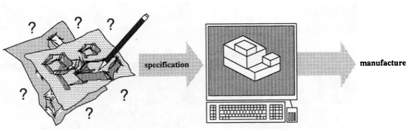
cision and detail that is most often unavailable until a later stage. On the other hand, while aiming to support the ear-liest stages of form design, computer supported sketching systems are simply electronic sketch pads that record a de-signer's 2D sketches. They provide little support for mod-elling the geometry implied by the sketches. One research direction in this area has, therefore, been the interpretation of diagrams and sketches. For instance, a pen-based proto-type diagramming environment for early stages of design, the Electronic Cocktail Napkin system (Gross, 1996), pro-vides facilities for recognition and parsing of 2D diagrams, and for establishing relations found in a diagram as con-straints on elements of the schematic drawing. However, in general, the initial geometric configuration of a product is most often conducted outside existing CAD systems using pencil and paper (Fig. 1). Only when they are fully devel-oped, the corresponding geometric designs are transferred into such a system for, for example, detailed analysis, visu-alization, etc. Reflecting an early commitment and trial-and-error approach to design, these systems are therefore unable to provide the required support for early geometric design. Clearly, if it is to support the early geometric configura-tion design, a CAD system should provide utilities for the rapid capture and evaluation of vague models, and support the further iterative and incremental development of the cap-tured models. This paper presents our pilot investigation into the development of such a system—GEMCON. The sys-tem considers rapid and qualitative spatial configuration as a significant element of early geometric design, where a de-signer investigates the structural or topological organiza-tion of a product without committing to unnecessary details. It aims to reason about, maintain and represent the config-uration solution space defined by geometric constraints rather than only a distinct solution point satisfying the constraints. Furthermore, constraints may be introduced into a config-uration incrementally as a design progresses and use of the system does not require a user to follow a specific, fixed, or predefined sequence. Concepts behind the system are pre-sented first (Section 2), followed by a description of the rep-resentation framework (Section 3), and the processing
mechanism (Section 4) developed. Examples of using the system are described in Section 5. Finally, a discussion is presented in Section 6.
2. VAGUE GEOMETRIC MODELLING
The major goal of the GEMCON system is to support the incremental modelling of vague geometric configuration. More specifically, it seeks to support a user in establishing geometric configurations using vague, along with precise, geometric information including shape, size, location and orientation, and in gradually evolving the configurations into concrete and precise models. This requires the develop-ment of (a) a framework that is capable of representing geo-metric configurations with evolving levels of vagueness or precision, and (b) a reasoning mechanism that supports the manipulation on the model.
Our own observation into early design and that from ex-isting research have led us to an overall philosophy, which has provided the conceptual basis for the system. This phi-losophy encompasses our view on a number of important aspects summarized below (Guan & MacCallum, 1996).
• The relation between the user and the system. The sys-tem should play, in general, the role of an Intelligent Design Assistant (MacCallum et al., 1985), which adopts a role secondary to the user, but can actively participate in the design process.
• A parametric and constraint-based computational model
of geometric design. Geometric design is viewed as a
process of establishing the geometric properties of a prod-uct to the extent that is required for physically manu-facturing the product. The geometric properties are defined by a set of parameters that characterize or describe the geometric configuration of the product, that is, its overall shape and size and the shape, size, loca-tion, and orientation of its constituent components. These properties are completely and uniquely defined if values of all the parameters are fully and uniquely
[image:3.595.98.500.599.727.2]manufacture
TTTTTI| |
defined. Values of the geometric parameters are speci-fied through constraints. An activity or action of con-straint manipulation that changes the possible values of the relevant geometric parameters is considered as a com-mitment toward the geometric design of the product.
• A minimum commitment modelling principle. This prin-ciple states that a commitment that is modelled in a CAD system should not be greater than that desired and requested by the user. In other words, the system should strive to facilitate the capture of the solution space defined by a piece of geometric constraint (vague or precise) rather than that of a specific solution point in the space.
• An incremental refinement principle. This comple-ments the minimum commitment modelling principle by requiring the system to support the gradual refine-ment of the modelled design solution space in steps that are sufficiently small to maintain commitment at a minimum.
The GEMCON system is being built to provide a platform for exploring and experimenting with the above ideas. As a pilot study, the scope of investigation has so far been lim-ited to the class of geometric configuration problems based on simple geometric information described in this paper. This was done on the basis that a) because of the great complex-ity involved in the problem, for the time being, there is a need to simplify the investigation into the implications, is-sues and challenges related to the above ideas, b) such prim-itive geometric information could provide a reasonable resource for modelling simple, abstract, and rough geomet-ric configurations as occur during the early stage back-of-the-envelope type of design. In the following sections, the representation and processing mechanism developed for the system will be described.
3. REPRESENTATION
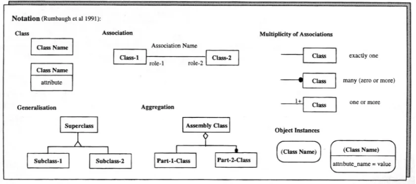
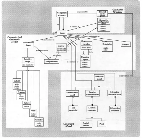
The framework for representing a geometric configuration within GEMCON is shown in Figure 3 using the OMT no-tation (Fig. 2) developed by Rumbaugh et al. (1991). For clarity and simplicity, only the key entities are included. The representation can be viewed as consisting of three parts:
geometric structure, which provides the required elements
for representing a geometric configuration consisting of ob-jects at different levels of details; parameterized geometric
model, which provides the parametric representation of the
approximately or precisely defined geometric properties of each object; and constraint models, which capture high-level geometric design constraints that define the param-eters characterizing the geometric properties of objects. Each of these three parts is explained below in more detail.
3.1. Geometric structure
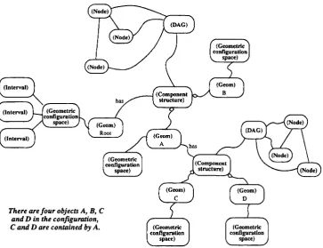
As will be described later, an entity called geom is used to encapsulate the geometric properties of an object. To model a geometric configuration with different levels, each geom object, no matter at which level, has a component structure that contains other geom objects that the "parent" geom ob-ject may have as its components. A component structure is represented by a directed acyclic graph (DAG). For exam-ple, object A contains objects C and D can be represented as shown in Figure 4. Note that any objects that are not con-tained by another object, here A and B, are considered to be contained by a root geom object, which provides the basic space for configuring the objects.
Each geom object is associated with a geometric config-uration space (GCS) (which is currently the minimum or-thogonal bounding box of the geom object). The GCS provides a physical boundary or space to enclose all the geom objects contained by the geom object to which the GCS is
Notation (Rumbaugh et al 1991):
Class Association Multiplicity of Associations
Class Name Association Name
Class Name
attribute
I role-1 role-2 1
Class-2 Class
Generalisation Aggregation Class
Superclass
T
Subclass-1 Subclass-2
Assembly Class
1 4 Part-l-Class Part-2-Class
Object Instances
exactly one
Class many (zero or more)
one or more
(Class Name) | (Class Name)
[image:4.595.89.510.560.746.2]I attnbute_name = value
290
Component structure
has
is reprcsenled by Directed acyclic
graph
Geometric Structure
Parameterised Geometric
Model
size parameter
Cuboid
width depth height
Frustum
top
radius
height
Sphere
radius
Prism
radius sides
Size constraint model
Constraint model
Location constraint model
Size constraint
I
is represented by
Orientation constraint model
Location constraint
Cylinder
radius height
1
Orientation constraint
Constraint Model
Spatial
[image:5.595.60.542.84.552.2]relation Point
Fig. 3. Representation structure.
associated. With respect to Figure 4, for example, the GCS associated to the geom entity representing object A pro-vides the space for enclosing the two geom entities repre-senting objects C and D, respectively, while the GCS associated to the root geom entity provides the space for enclosing the two geom entities representing objects A and B. A GCS is currently a cuboid represented by three inter-vals corresponding to the three axes of the coordinate system.
3.2. Parameterized geometric model
An entity called geom is used to capture the geometric prop-erties of a physical object. It encapsulates the inherent
attributes of shape and size, and arrangement attributes of orientation, and location of the object. The shape may be any primitive—cuboid, frustum, sphere, prism, cylinder— whose size is characterized by size parameters1 such as width, depth, etc. as shown in Figure 3. The value of a size param-eter can be defined approximately or precisely and is rep-resented by an interval. An interval is a bounded set of real numbers represented by a lower and an upper bound (Moore, 1979).
There are four objects A, B, C and D in the configuration,
C and D are contained by A. I (Geometric I configuration
^ space) J
[image:6.595.118.482.77.356.2](Geometric configuration . space) t Fig. 4. Representation of a geometric structure.
The orientation of an object is characterized by the rota-tion the object has with respect to a global coordinate sys-tem. This is determined by the rotation angles, the coordinate axis about which a rotation is carried out, and the order of rotations about the axes.
The location of an object is characterized by a parameter, called a datum point (which is chosen as the geometric cen-ter of the object). This datum point lies in a 3D cubic
un-certain region (UR), which captures the approximation or
uncertainty associated with the location. An uncertain re-gion is represented by three intervals along, respectively, the X, Y, and Z axes of the coordinate system associated with the corresponding geometric configuration space which specify the allowable x, y, and z coordinates of the corre-sponding datum point.
A boundary model (B-model) can be constructed to rep-resent an object. A boundary model refers to a geometric model constructed via the boundary representation scheme developed in the field of geometric modelling (Requicha,
1980; Spatial Technology, 1992).
Figure 5 illustrates an example of the parameterized model of an object with a cuboid shape. The three pieces of size information—width between 15 and 18, depth approxi-mately 10 and height exactly 20—are given through inde-pendent size constraints (discussed in Section 3.3), and are converted into three intervals shown in the figure. The method for deriving size intervals from independent size con-straints is discussed in Section 4.3. Note that the degree of approximation used for converting depth «* 10 is assumed
to be 1. The orientation of the object is not specified and is thus given a default setting. The location of the object is not specified either. The object is therefore assumed, by de-fault, to be moveable in the entire geometric configuration space. The method used for deriving UR bounds from spa-tial relations is illustrated in Section 4.2.
3.3. Constraint models
A size constraint model, an orientation constraint model, and a location constraint model are associated with each geom ject to hold all the constraints specified for all the geom ob-jects contained by this object. These constraints are used to derive the values of the correspondi ng geometric parameters.
• Size Constraints: The system currently supports inde-pendent size constraints, each of which constrains only one size parameter. They are of inequality type
(includ-ing x «* a, x < a, x < a, x > a, x > a), range type (x =
[a,, a2]), and equality type (x = a). Here, x denotes a
size parameter, a, ax, and a2 real numbers.
• Orientation Constraints: The system currently sup-ports the rotation of objects in multiples of 90 degrees around the coordinate axes.
(Interval)
x-extent
A is a cuboid with width between 15 and 18, depth approximately 10, height exactly 20.
(Geometric configuration space)
lower bound = 0 upper bound = 100
(Interval)
z-range
lower bound = 10 upper bound = 90
(Size parameter)
width
(Interval)
lower bound = 1 5 upper b o u n d = 1 8
(Size
parameter)
depth
(Size
parameter)
height
(Interval)
lower bound = 9.5 upper bound = 10.5 I
I (Interval) x-range
lower bound = 7.5 I upper bound = 92.7 I V
(Interval)
y-range I lower bound = 4.75 I upper bound = 95.251
(Interval)
[image:7.595.90.509.76.328.2]lower bound = 20 upper bound = 20
Fig. 5. Parameterized representation of an object with a cuboid shape.
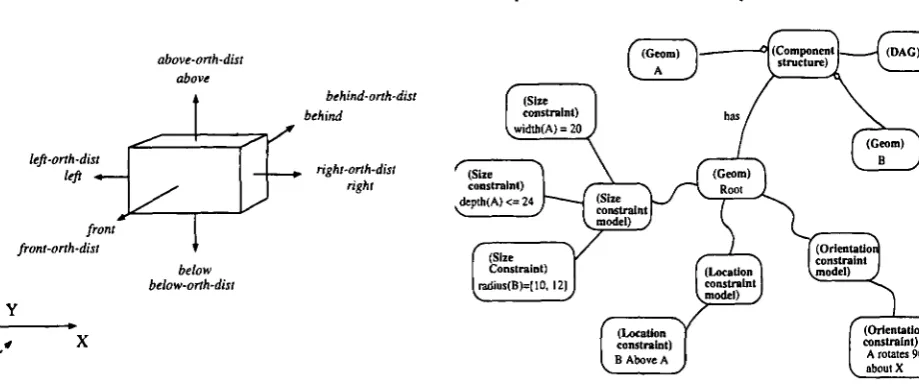
constrains the location of an object in relation to other objects in the same level of configuration. The types of spatial relations currently supported are shown in Fig-ure 6, where "above-orth-dist" stands for above with an
orthogonal distance (the same notation applies to the
oth-ers). It can be observed that, the definition of spatial re-lations as shown in Figure 6 means that {above,
above-orth-dist, below, below-orth-dist} relations only affect
the URs of the relevant objects in the Z direction, while
[right, right-orth-dist, left, left-orth-dist) and {behind, behind-orth-dist, front, front-orth-dist} only affect the
URs in the X and Y direction, respectively.
Each constraint is associated with an importance factor and a time stamp, which are used in the reasoning mechanism for resolving constraints (Section 4). The importance factor is a number that indicates how important it is for the asso-ciated constraint to be satisfied. The time stamp records the time when the associated constraint is established in the con-figuration process.
As an example, Figure 7 shows the representation of con-straints related to an example geometric configuration.
A: cuboid, width is 20, depth is smaller than or equal to 24, rotate by 90 about X axis.
B: sphere, radius is between 10 and 12, placed above A.
lefi-orth-dist left -.
jr
front front-orth-dist
above-orth-dis above
I
1
below below-orth-dist
behind-orth-dist behind
y
1
r right-orth-dist
J right
o
I (Size constraint) ^widlh(A) = 20
(Size constraint) depth(A)<=24
(Size Constraint) lradius(B)=[10, 12] I
* (Component L
structure) (DAG)
has ,
user
(S!K \ S
constraint model) J
f \
(Location constraint) 1 B Above A I
I (Geom) " \ Rool X
[ (Location | 1 constraint 1
Imodel) J
f
X ,
[ (Orientation]constraint Vmodel) J
( (Orientation
constraint) A rotates 90 V about X
[image:7.595.80.540.563.758.2]specification
Update Constraint
Models
Satisfy Constraints
solution
Update Configuration
Model
relevant geom objects
[image:8.595.94.505.79.164.2]abort
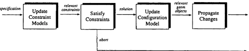
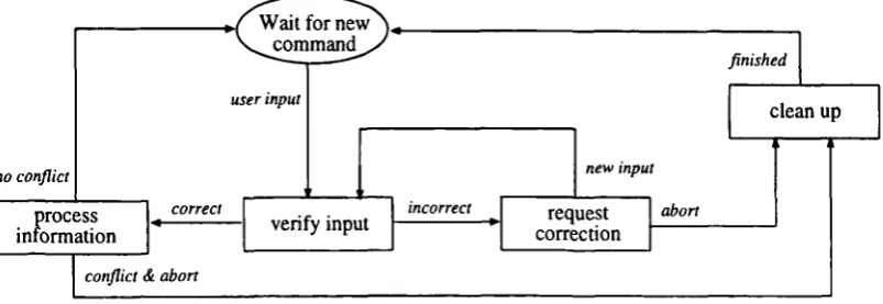
Fig. 8. Key stages of geometric information process.
Propagate Changes
To summarize, the framework shown in Figure 3 repre-sents geometric configurations consisting of objects at dif-ferent levels of details. The geometric properties of each object are encapsulated by a geom entity. They are charac-terized by size, orientation, and location parameters de-fined by a set of size constraints (of inequality, range, and equality types), orientation constraints, as well as spatial re-lations. Approximate or precise values for size and location parameters are captured by size ranges and location uncer-tain regions, respectively.
4. PROCESSING OF GEOMETRIC INFORMATION
A constraint-based mechanism, consisting of the key stages shown in Figure 8, has been developed to support the ma-nipulation of geometric configuration represented via the above framework. This mechanism is applied to process size, orientation, and location information related to a geometric configuration. Each of the stages is described briefly in the following.
4.1. Update of constraint models
Constraints are created based on information on the size, ori-entation and location of objects, and are integrated into the rel-evant constraint models. When a new constraint is specified that constrains an entity that has already been constrained, in-stead of always taking the newly specified one, the system cur-rently acts upon one of the following resolving strategies:
• IMPORTANCE—For a given set of constraints on the same parameter or object, if they have different
impor-tance factors, then always select the most important
constraint, that is, the one with greatest importance fac-tor, otherwise refer to the user for a decision.
• TIME—For a given set of constraints on the same pa-rameter or object, always select the most recently spec-ified constraint, that is, the one with the most recent
time stamp.
• USER—For a given set of constraints on the same pa-rameter or object, always refer to the user for a decision. • AUTOMATIC—For a given set of constraints on the same parameter or object, always resolve using a
com-bination of the above strategies. As an example, the automatic strategy for resolving size constraints is de-fined as that shown in Figure 9. There, an additional strategy, REFINEMENT, is available that resolves size constraints based on the Boolean intersection of the value sets of the given constraints. If a nonempty in-tersection exists, then the system uses the inin-tersection set as the value range of the corresponding size param-eter, otherwise it refers to the user for a decision.
The default strategy is set to be AUTOMATIC.
Once updated, a set of relevant constraints are extracted and passed to the satisfaction process.
4.2. Satisfaction of constraints
Constraints obtained in the above process are satisfied to generate values for the corresponding geometric param-eters. Size and orientation constraints handled by the
cur-Is the Boolean intersection of the value sets of the new and old constrai
empty?
Resolving using REFINEMENT strategy
Resolve using
IMPORTANCE
strategy
Yes
Resolve using TIME strategy
No
Resolve using USER strategy
[image:8.595.308.550.479.745.2]rent system include only independent ones that do not involve more than one size parameter or object. Therefore, this pro-cess does not need to solve size and orientation constraints. The location of an object in a configuration is given ei-ther in spatial relations or in a point and is represented by a datum point that lies in a UR defined by three ranges. To derive the bounds of the URs of objects, the solving process first formulates a set of constraints on these bounds from the spatial relations or points, and then proceeds to solve the formulated UR constraints.
4.2.1. Formation of UR constraints
This subprocess interprets location constraints into con-straints on the bounds of the corresponding URs (referred to as UR constraints). As an example, Figure 10 illustrates the formulation of UR constraints in a simple situation where object Gp is specified to be above object Gr and Gp,
and Gr have no above or below relations with other ob-jects in the same configuration. Note that the size of an object used here is that of the orthogonal bounding box of the object. When the location of an object is not specified,
GIVEN: above(Gp, Gr), where Gp is the primary object and GT the reference object, and Gr and GT
have neither above nor below relation with other objects in the same configuration,
the bounds of geometric configuration space GCS in the Z direction: GCSt = \GCST. GCSZ],
the size of GT in the Z direction: SIZErz = \SIZETI, SIZETZ],
the existing values of the bounds of the UR of GT in the Z direction : UR'TZ = \UR'TX. UR'TZ],
where URLrz = GCSr + SIZET. 12 and UR'TZ = GCSZ - SIZErT/2,
the size of Gp in the Z direction: SIZEpz = \SIZEpz, SIZEpz],
the existing values of the bounds of the UR of Gp in the Z direction: UR'pz = \UR'pz. UR'pz],
where UR'pz = QCS_Z + SIZEpz/2 and JjRipz = GCSZ - SIZEpj2.
TO DERIVE: new constraints on \URpz, U~Rpz] and [t/Hrz, UR.TZ\.
FOR THE LOWER BOUNDS:
IF the space between GCSZ upper bound and GT placed at its corresponding UR lower bound
is larger than Gp
THEN form the following constraints:
VRft = URrz + (SIZErr + SIZE.r)/2
URrZ = UKrz ELSE declare spatial conflict.
FOR THE U P P E R BOUNDS:
IF the space between GCSZ upper bound and GT placed at its corresponding UR upper bound
is larger than Gp
THEN form the following constraints:
URpZ - GCSz - SIZEpx 12
URrz = UR'rz
ELSE IF Gr is not point fixed
and its corresponding UR upper bound can be reduced to accommodate Gp
THEN form the following constraints:
URpZ = GCSz-SIZE,pj2
URrz = VKTZ - SIZE_pz
E L S E declare spatial conflict.
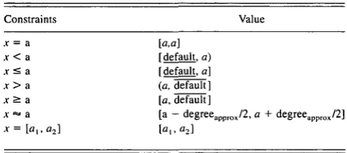
Table 1. Conversion of independent size constraints to value ranges
Constraints
x = a x< a .v< a x> a
j > a
x "» a
[o,a] [default, a) [default, al (a, default] [a, default] [a - degreeapprox
Value
12, a + degreeapprox/2]
the object is assumed, by default, to be moveable in the entire geometric configuration space. Following Retz-Schmidt (1988), the object whose location is determined by a spatial relation, here Gp, is called a primary object,
and the object to which the relation is specified, here Gr,
is called a reference object.
A graphical interpretation of the definition of UR via an
above-orth-dist relation can be found in the sample
config-uration session in Section 5 (see Fig. 13).
4.2.2. Solving of UR constraints
The set of UR constraints derived from spatial relations or point positions is solved through a generic constraint solver, currently CLP(R) (Heintze et al., 1991). This gen-erates values for the corresponding bounds of the URs.
4.3. Update of configuration model
The relevant uncertain regions are updated according to the bound values derived from the above satisfaction process. The rotation angles, axes, and order that describe the orien-tation of an object in relation to the global coordinate sys-tem are also modified according to any new orientation constraints.
To update the value of a size parameter constrained by an independent size constraint, the system uses Table 1 to gen-erate the bounds of the corresponding value range. Note that because jcAa, where A £ {<, < , > , ^ } only defines one value bound for a size parameter x, a default lower bound and upper bound, here denoted by default and default, respec-tively, are used to provide the missing bound. They are pro-visional and can be changed by a user. The round brackets ")" and "(" in the ranges for x < a and x > a, respectively, mean that the number a is not included in the corresponding value ranges.2 To convert x «* a, a default degree of approx-imation, degreeapprox (^0), is introduced. It defines the width of the interval as shown in Table 1.
2In the current system, exclusion of a in x < a or x > a is treated as that
the upper bound of x < a or the lower bound of x > a takes a - S or a +
S, respectively, where S is a very small positive number in relation to a.
4.4. Propagation of changes
Finally, changes to objects are propagated throughout the relevant parts of the whole configuration model to maintain the global consistency. Currently, this includes two aspects:
• A reevaluation of the relevant set of location con-straints. This is necessary because any changes in size and orientation lead to changes in the UR bounds of the relevant objects.
• A propagation to the sublevel components of a changed object. This currently includes a reevaluation of all lo-cation constraints existing among the component ob-jects in response to the changed parent object (the container).
5. USE OF THE SYSTEM
The GEMCON system has been implemented using Harle-quin Lisp Works (Common Lisp and CLOS) (HarleHarle-quin, 1994) running on a Silicon Graphics platform. To highlight the underlying ideas, the major modelling operations devel-oped are briefly described and their use in constructing and evolving a geometric configuration model is illustrated.
5.1. Major modelling operations
Table 2 presents the set of operations that can be used for developing geometric configurations. Initial construction of models can be carried out through a type 2 operation,
make-geom, which takes shape, size, location, and orientation
in-formation on the object to be modelled. A default is used where a value is required but not specified.
Further development of the initial model can be ap-proached incrementally through type 2 and 3 operations. Overall, these operations support three types of modifica-tion to an initial model: incremental, which adds missing items to a model to make it less incomplete; refinement, which fine-tunes a model by reducing associated approxi-mations; and retraction, which removes an existing item from a model.
The general flow of control implemented for these oper-ations is shown in Figure 11. When an operation is invoked, the system first checks the correctness of the input informa-tion. A faulty input is sent to a correction process, which allows the user to amend the input or to abort the whole operation. If the input appears correct, it is then processed through the constraint-based mechanism described earlier. Whenever an operation is aborted as a result of spatial con-flict or the user's change of plans, a clean-up process is in-voked to ensure that no changes have been made to the corresponding model by the operation aborted.
5.2. A Sample modelling session
geo-Table 2. A selection of configuration modelling operations
Type Operation Brief description
1. Establish configuration environment
2. Explore component geometry
3. Explore spatial arrangement
4. Inspect configuration model
set-gcs-size Modify the size of the geometric configuration space of a given geometric object set-default-shape Change the default shape type
set-size-approx Set the degree of approximation to be used in representing approximately specified value of a size parameter
set-size-lb Set the default lower bound of the interval representation for the value of a size parameter set-size-ub Set the default upper bound of the interval representation for the value of a size parameter set-strategy Choose the strategy to be used by the system in resolving constraints
make-geom Create a geometric model based on vaguely or precisely specified geometric information delete-geom Delete a given geometric object
add-scs • Modify the size of a given geometric object add-ocs Modify the orientation of a given geometric object specify-rot-order Specify the order in which rotations are performed add-lcs Modify the location of a given geometric object refine-ur Refine the location uncertain region of a geometric object delete-constraint Delete a geometric constraint
display-geom Display information related to a given geometric object
display-strategy Display the strategy used currently for resolving a given type of constraint explain-strategy Give brief explanation of a given constraint resolving strategy
display-env Display variables that define the configuration environment
metric configuration model. For ease of description, operations in the scenes are numbered. Where applicable, the figure num-ber that corresponds to an operation is also included after the operation number for ease of reference. Input to the system is presented in bold (see Figs. 12, 15, and 18-20). The > symbol at the beginning of each input is the prompt of the Lisp Listener through which the system is invoked. To save space, layout of some of the textual output from the system is changed and unimportant texts are omitted.
5.2.1. Working with vague information
Initially, the user has the following information about a geometric configuration:
It contains two objects. The first one is a cuboid with its
width, depth, and height each being exactly 20. The
sec-ond object is placed above the first one, and is also a
cu-boid with a width between 16 and 18, depth about 5, and
height no more than 14. The orthogonal distance
be-tween the two objects is 5.
Scene 1 (Fig. 12) shows the modelling of such a vaguely specified configuration. Operation [1.1] and [1.2] create
geoml and geom.2 to represent the two objects described
above. The size ranges of the objects captured in the system and their UR bounds are shown by [1.4]—[1.7]. The gener-ated configuration model therefore corresponds to the solu-tion space illustrated in Figure 13. Namely, geoml is an exactly sized cuboid located in the UR of ([10.0,90.0], [10.0, 90.0], [10.0, 75.0]). Note that, for minimum commitment, an object whose location is not specified is assumed to be moveable in the entire space of the corresponding GCS (here ([0.0, 100.0], [0.0, 100.0], [0.0, 100.0])—see Operation [1.8]), as is the case for geoml (except in the Z direction,
no conflict
proc inform
Wait for new >
Vcorn
user input
sss ation
correct
m a n d y '
verify input incorrect
conflict & abort
new input
request correction
abort
finished
[image:11.595.47.553.98.325.2]clean up
[image:11.595.100.502.617.755.2]> (make-geom :size '(((width = 20)) ((depth - 20)) ((height = 20)))) [1.1]
GEOM1
> (make-geom -.size '(((width s 16 -> 18)) ((depth ' = 5)) ((height <= 14))) [1.2] location '(((above-orth-dist geoml 5))))
GEOMS
> (display-geom geomO) [1.3] (Figure 14)
> (display-geom g e o m l :aspect 'size-value) [1.4] <Size of GEOM1>
WIDTH:
Lower Bound — 20 Upper Bound 20 DEPTH:
Lower Bound — 20 Upper Bound — 20 HEIGHT
Lower Bound — 20 Upper Bound 20
> (display-geom g e o m l taspect *ur) [1.6] (Figure 13(b)) < Location uncertain region of GEOM1>
X-RANGE:
Lower Bound — 10.0 Upper Bound — 90.0 Y-RANGE:
Lower Bound — 10.0 Upper Bound — 90.0 Z-RANGE:
Lower Bound — 10 Upper Bound — 75
> (display-geom geom2 :aspect 'size-value) [1.7] (Figure 13(a)) <Siae of GEOM2>
WIDTH:
Lower Bound — 16 Upper Bound — 18 DEPTH:
Lower Bound — 4.75 Upper Bound — 5.25 HEIGHT:
Lower Bound — 10.0 Upper Bound — 14
> (display-geom geom2 :aspect 'ur) [1.7] (Figure 13(b)) < Location uncertain region of GEOM1>
X-RANGE:
Lower Bound — 8.0 Upper Bound — 92.0 Y-RANGE:
Lower Bound — 2.375 Upper Bound 97.625 Z-RANGE:
Lower Bound — 30 Upper Bound 95
> (display-env) [1.8] (Figure 13) •DEFAULT-GCS-SIZE* ((0.0 100.0) (0.0 100.0) (0.0 100.0))
•DEFAULT-DEPTH* (15 0 15.0) •DEFAULT-HEIGHT* (10.0 10.0) •DEFAULT-RADIUS* (10.0 10.0) •DEFAULT-WIDTH* (20.0 20.0) •DEFAULT-SHAPE-TYPE* CUBOID •DEFAULT-IMPORTANCE* 0.0
•DEGREE-OF-APPROXIMATION4 0.5
•DISPLAY-LEVEL* 1
•CURRENT-SC-RESOLVING-STRATEGY^ AUTOMATIC
Fig. 12. Interaction Scene 1.
*default-298 X. Guan et al.
height
100
9 5 •
75"
geometric configuration space
\ location uncertain region ofgeom2
i (
O V-N " 16 18 width
degree of approximation 0.5
upper bounds of size i,-"", corresponding to
lower bounds of size
geoml
width
8 10 90 92 1 0 0 X
location uncertain region of geoml
(a) The size solution space of geom2 (not to scale).
[image:13.595.93.514.77.379.2](b) The location solution space of geoml and geom2 (OXZ projection, not to scale).
Fig. 13. Solution space of the geometric configuration model established by Operations [1.1] and [1.2] and shown by Operations [1.4H1.8].
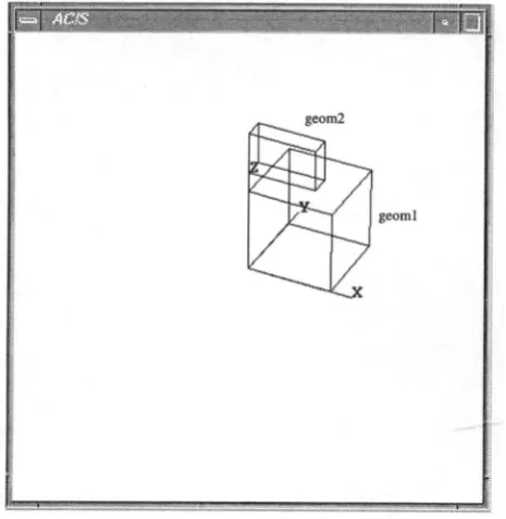
height* shown by operation [1.8]. A wire-frame display of
the boundary model of a configuration instance included in the solution space, which corresponds to the minimum size and lower-left-front corner of the corresponding UR, is shown in Figure 14. This is generated by operation [1.3] using a geometric modeller, ACIS (Spatial Technology, 1992), integrated in the system. For ease of viewing, labels are added to the display manually to identify the correspond-ing geom objects.
5.2.2. Further development of objects
While the user could continue to add into the configura-tion other objects at the same level as geoml and geoml, he/she may also choose to focus on more detailed develop-ment of an existing object, say geoml. This can be a) cre-ation and iterative modificcre-ation of its subcomponents or b) iterative modification of its size, orientation, and location. Scene 2 illustrates the use of the system in assisting these two aspects of configuration development. Part A (Fig. 15) shows the creation and iterative modification of the subcom-ponents of geoml to achieve a specific configuration goal. Op-eration [2A.1] makes a subcomponent, geom3. After that, in [2A.2], the user attempts to create, and place above geom3, a subcomponent with a height of 30. Because 30 is larger than the space (which is 20 — 10 = 10) left between geomi and the corresponding configuration space (the orthogonal
bound-ing box of the parent object geoml, here the same as geoml itself), creating the subcomponent would cause a spatial con-flict. When notified of the situation, the user withdraws the operation and makes a smaller object instead ([2A.3]). An ex-ample of the model defined after [2A.3] is graphically dis-played in Figure 16a. Figure 16b and 16c show the local geometric structure of geoml and global structure of the re-sulting configuration, respectively, where geomO corresponds to the most geom object described in Section 3.1.
Next, the goal of the user is to change the height of geom3 to 18 while maintaining its current orientation. To do this, the user first tries to change the height directly ([2A.7]). Because this would cause a spatial conflict as detected by the system, the user then explores another way: first alter-ing the orientation of geom3 ([2A.8]), then changalter-ing its
height ([2A.9]). This, however, has altered the orientation
geom2
[image:14.595.55.288.85.324.2]georal
Fig. 14. An instance of the geometric configuration model.
do now is to remove the above relation ([2A.14]) and then rotate geom3 back to its original orientation ([2A.15], Fig-ure 17b).
The illustrated is only one way of approaching the targeted configuration iteratively using the available operations. The user could achieve the same configuration goal in several other ways or sequences of using the operations, for example
• specifying geomS behind geom3 —> deleting the exist-ing geomS above geom3 relation —» increasexist-ing the height of geom3 to 18;
• deleting the geomS above geom3 relation —> specify-ing geom5 right geom3 —> increasspecify-ing the height of
geom3 to 18;
and so on.
Part B of Interaction Scene 2 (Fig. 18) shows the use of the system in modifying the size ([2B.1]), orientation ([2B.2]), and location ([2B.3]-[2B.8]) of geoml itself. The uncertain region of geoml in the Z direction is refined from [10, 75] ([2B.3]) to [30, 75] ([2B.5]) through the operation
refine-ur ([2B.4]) by raising its lower bound. Later in
Op-eration [2B.7], it is replaced by that derived from an above relation. This is because, in the current system, the UR of an object is allowed to be changed directly through refine-ur only if its location is not dependent on any other objects. In other words, UR bounds derived from spatial relations su-persede those from refine-ur.
5.2.3. Use of resolving strategies
As discussed earlier, the system supports a number of strategies for resolving constraints. Scene 3 (Fig. 19) shows
how this is used in the case of size modification. In Oper-ation [3.3], the user tries to change the depth of geom7. Because the default resolving strategy is AUTOMATIC (see Operation [1.8]) and the existing constraint, depth = [24,27] specified in [3.1], already satisfies the new constraint, depth 2: 8 [i.e., the Boolean intersection of these two constraints is not empty (refer to Fig. 9)], the depth is not changed (compare [3.2] and [3.4]). Thus, if the user's intention was to enlarge the existing solution space for depth, then it was not achieved. To do so, the user needs to use one of the other strategies, TIME, IMPORTANCE, or USER. After switching to TIME ([3.5]), the user succeeded in enforcing the new constraint ([3.6]).
5.2.4. Dynamic change of configuration space and deletion of object
A geometric configuration space can be modified dynam-ically if necessary, e.g. to accommodate larger objects. Scene 4 (Fig. 20) shows how this can be done. In Operation [4.1], the user tries to modify the width of geoml to 110, which fails because it exceeds the size of the configuration space of geom.7-100 (defined by the default shown in Op-eration [1.8]). This, however, is accommodated ([4.3], Fig. 21a) after the user changes the size of the GCS to 300 along the X, Y, and Z directions ([4.2]).
Finally, objects can be deleted from a configuration as illustrated by Operation [4.5]. The upper most level of the geometric structure so far and the graphical display of an instance of the corresponding model are shown in Fig-ure 21b and 21c.
6. DISCUSSION
6.1. Incremental modelling of vague geometry
In this paper, we have presented a prototype system for sup-porting the early stages of geometric design following the conceptual basis presented in Section 2. Within the current scope of investigation, the system supports the user in ap-proaching the development of a geometric configuration in a minimum commitment way by supporting incremental and iterative definition and evolution of configurations using vague size and location information. Two observations can be made on the type and content of the information used in the sample session:
> (make-geom :shape 'cylinder [2A.1] :size '(((radius = 5)) ((height = 10)))
:contained-by g e o m l ) GEOM3
> (make-geom :shape 'cylinder [2A.2] :size '(((radius = 5)) ((height = 30)))
l o c a t i o n '(((above geom3))) :contained-by g e o m l )
There is not enough space available in the Z direction for placing GEOM4. Please choose from the following:
0 : Abort PICK: 0 Please confirm:
0 : Abort 1 : Allow PICK: 0
GEOM4 is deleted.
> (make-geom :shape 'cylinder [2A.3] :size '(((radius = 3)) ((height = 5)))
ilocation '(((above geom3))) :contained-by g e o m l )
GEOM5
> (display-geom geomO rlevel 2) [2A.4] (Figure 16(a))
> (display-geom g e o m l raspect 'local-cs) [2A.5] (Figure 16(b))
> (display-geom geomO :aspect 'global-cs) [2A.6] (Figure 16(c)) > (add-scs geom3 '(((height = 18)))) [2A.7]
Using ((HEIGHT GEOM3) = 18). Reasons are:
The current conflict resolution strategy is set as: AUTOMATIC
((HEIGHT GEOM3) = 18) is more recent than ((HEIGHT GEOM3) = 10) There is not enough space available in the Z direction for placing GEOM5 in relation to GEOM3. Please choose from the following:
0 : Abort PICK: 0
> (add-ocs geom3 '(((rotate 90 (y wcs))))) [2A.8]
> (add-scs geom3 '(((height = 18)))) [2A.9]
> (display-geom geomO :level 2) [2A.10] (Figure 17(a))
> (add-ocs geom3 '(((rotate 0 (y wcs))))) [2A.11] Using (ROTATE GEOM3 0 (Y WCS)).
Reasons are:
The current conflict resolution strategy is set as: AUTOMATIC
(ROTATE GEOM3 0 (Y WCS)) is more recent than (ROTATE GEOM3 90 (Y WCS)) There is not enough space available in the Z direction for placing GEOM5 in relation to GEOM3. Please choose from the following:
0 : Abort PICK: 0
> (add-lcs geom5 '(((behind geom3)))) [2A.12]
> (add-ocs geom3 '(((rotate 0 (y wcs))))) [2A.13] Using (ROTATE GEOM3 0 (Y WCS)).
There is not enough space available in the Z direction for placing GEOMS in relation to GE0M3. Please choose from the following:
0 : Abort PICK: 0
> (delete-constraint aboveO) [2A.14]
> (add-ocs geom3 '(((rotate 0 (y wcs))))) [2A.15]
[image:15.595.90.506.98.582.2]> (display-geom geomO :level 2) [2A.16] (Figure 17(b))
301
geom2
geom5
geom3
geoml
(a) An instance of the geometric configuration model
[image:16.595.188.421.84.332.2](b) Local component structure (c) Global component structure
Fig. 16. Addition of subcomponents to geoml.
• A piece of information used could simply be:
- an addition of something about an object which has not been defined,
- a refinement to or redefinition of something already defined (coarsely or not),
- a retraction, from the model, of something already defined.
Figure 22 illustrates the process in the sample session in developing the specific geometric configuration, where a directed line denotes the application of the associated op-eration to the directed geom object. The process is clearly
iterative and nonsequential, as shown by those lines
link-ing objects in various stages of the process. It is interative in the sense that the user can return to a previously defined
geom object carrying out modifications. It is also
non-sequential in that the user can define any geom object at any stage. The modelling operations can be invoked in dif-ferent sequences/orders to difdif-ferent objects to achieve the same goal (Scene 2A). Therefore, they are in this sense flexible and support iterative and nonsequential configura-tion design.
[image:16.595.117.484.371.503.2]7
geomS \ ^ h
geom3
mm
geom2
wmmmmm
' I geoml
[image:17.595.51.289.81.326.2](a). Height of geom3 is changed but orientation is altered as well.
|^3HE3Saj|HKB|i|j|p|j||||8aB|BM|S|||
geom5
geom3
geom2
fp2L
/
geoml(b). Height of geom3 is changed and orientation is maintained.
Fig. 17. Configuration of geom3 and geomS with geoml.
reasoning and propagation of the effect of a modelling op-eration, consistency checking and model presentation in var-ious ways. The role of the system is consistent with that of the general Intelligent Design Assistant described in Mac-Callum et al. (1985).
Finally, we observe that the parametric and constraint-based model of geometric design is descriptive in the sense that it is close to an intuitive description of geometry and provides a natural description of design or engineering con-straints. The pilot study has also justified the feasibility of the corresponding representation framework to handle sim-ple geometric configurations investigated.
6.2. Relation to other work
This section relates the work presented in this paper to the relevant existing works from computer-based design sup-port systems, including systems that adopt a minimum com-mitment based approach, spatial layout systems, as well as constraint-based geometric design systems.
6.2.1. Existing systems adopting minimum commitment approach
In a previous paper (Guan & MacCallum, 1996), we have proposed the adoption of the minimum commitment prin-ciple in early geometric design support systems, and have reviewed its application in a number of areas including computer-based planning systems (Weld, 1994), engineer-ing design (Asimow, 1962; Dym, 1994), and a few computer-based design and manufacturing planning systems.
Minimum commitment, known as least commitment, is adopted, in a limited way, to permit ranges of values or choices in a number of design and manufacturing planning systems. For example, Baykan and Fox (1992) consider the constraint propagation mechanism used in their constraint based 2D lay-out system—WRIGHT—as a least commitment-based ap-proach in two aspects: it only removes from variable ranges those values that violate a constraint, and it selects constraints to be satisfied by design units instead of choosing specific locations.
ALADIN is an expert system developed for aiding ma-terials, in particular aluminum alloys, design (Farinacci et al., 1992). It treats alloy design as a planning problem and uses a combination of least commitment and overcom-pensatory methods for planning. The relevant design vari-ables can take ranges of values that "are kept as broad as possible until more data is present to force them to be re-stricted, which allows the system to avoid trial-and-error in selecting values."
Based on a design by least commitment approach, Man-tyla et al. (1989) proposed the use of relaxed feature models in a generative process planning system to avoid over-specifying geometric models to not restrict the subsequent manufacturing options. Following the design by least com-mitment approach, Hel Or et al. (1994) proposed the use of
soft constraints, that is, constraints that need not be
satis-fied exactly, in a probabilistic-constraints scheme for im-plementing a relaxed parametric design paradigm.
> (add-scs geoml '(((height = 30))))
> (add-ocs geoml '(((rotate 90 (y wcs))))) > (display-geom geoml raspect 'ur)
<Location uncertain region of GBOM1> X-RANGE:
Lower Bound — • 15.0 Upper Bound — 85.0 Y-RANGE:
Lower Bound — 10.0 Upper Bound — 90.0 Z-RANGE:
Lower Bound — 10 Upper Bound 75 > (reflne-ur geoml :z- 30)
> (display-geom geoml :aspect 'ur)
< Location uncertain region of GEOM1>
X-RANGE:
Lower Bound — 15.0 Upper Bound — 85.0 Y-RANGE:
Lower Bound — 10.0 Upper Bound — 90.0 Z-RANGE:
Lower Bound — 30 Upper Bound 75
> (make-geom) GEOM6
> (add-lcs geoml '(((above geom6))))
> (display-geom geoml :aspect *ur)
< Location uncertain region of GEOM1> X-RANGE:
Lower Bound 15.0 Upper Bound — 85.0 Y-RANGE:
Lower Bound — 10.0 Upper Bound — 90.0 Z-RANGE:
Lower Bound 20 Upper Bound — 75
[2B.1] [2B.2] [2B.3]
[2B.4] [2B.5]
[2B.6]
[image:18.595.92.513.82.475.2][2B.7] [2B.8]
Fig. 18. Interaction Scene 2—Part B.
1991). Minimum commitment design is encouraged by sup-porting the use of abstract feature-forms that can be modi-fied incrementally.
6.2.2. Spatial layout systems
The arrangement aspect of the GEMCON system is re-lated to systems developed for spatial layout, in particular, those that permit the description of layout problems in high-level spatial relations and inequality/equality constraints, and represent value ranges for dimensional and locational vari-ables. For instance, Chambon and ToUenaere (1987) described a rule-based expert system for sequentially placing mechan-ical components in 3D space. The model of a 3D component contains the description of its geometry and position in a space. The geometric description consists of two levels: a fixed solid geometry such as cylinders, "parallelepipeds," etc., and a parallelepiped enclosing the entity. The position of an en-tity is described by three coordinates, each of which is com-posed of "a reference that can be another coordinate or the
absolute fixed reference" and "a gap that can be a number or an interval [Xmin, Xm a x]." Qualitative relationships, such as
against_direction_x, centered_on, facing, are used to
de-scribe the constraints on the placement of entities. The sys-tem first selects the entity to be placed based on certain if-then rules, and if-then for the selected entity suggests predicates consisting of qualitative relationships or actions that create new entities. These qualitative relationships are then checked for their compatibility with one another, and translated into a numerical position. A list of entities in conflict with the en-tity being placed is formed for freedom reduction. Conflict be-tween two entities is then solved based on the strategy of "keeping the largest freedom space on the current entity" be-ing placed. The system selects objects with an age criterion and tries to solve the conflict with the entities in the list se-quentially starting from the first by finding a freedom paral-lelepipedic solution for each entity involved.
ap-> (make-geom :size '(((depth = 24 -ap-> 27)) ((width *= 5))) [3.1]
location '(((left geoml)) ((left geom6)))) GEOM7
> (display-geom geom7 :aspect 'size-value) [3.2] <Sizeof GEOM7>
WIDTH:
Lower Bound — 4.75 Upper Bound — 5.25 DEPTH:
Lower Bound — 24 Upper Bound 27 HEIGHT:
Lower Bound — 10.0 Upper Bound — 10.0
> (add-scs geom7 '(((depth >= 8)))) [3.3] > (display-geom geom7 :aspect 'size-value) [3.4] <Sizeof GEOM7>
WIDTH:
Lower Bound — 4.75 Upper Bound 5.25 DEPTH:
Lower Bound — 24 Upper Bound — 27 HEIGHT:
Lower Bound — 10.0 Upper Bound — 10.0
> (set-strategy 'sc 'time) [3.5] > (add-scs geom7 '(((depth >= 8)))) [3.6] Using ((DEPTH GEOM7) > = 8).
Reasons are:
The current conflict resolution strategy is set as: TIME
((DEPTH GEOM7) > = 8) is more recent than ((DEPTH GEOM7) = 24 -> 27)
> (display-geom geom7 :aspect 'size-value) [3.7] <Sizeof GEOM7>
WIDTH:
Lower Bound — 4.75 Upper Bound — 5.25 DEPTH:
Lower Bound — 8 Upper Bound — 27 HEIGHT:
[image:19.595.90.510.81.514.2]Lower Bound — 10.0 Upper Bound — 10.0
Fig. 19. Interaction Scene 3.
proach based on rules. Given a set of design units, it tries to derive feasible layouts of orthogonal rectangles where no two rectangles overlap. A set of four spatial relations, above,
below, to the left and to the right, are supported.
Addition-ally, the lower and upper bound of the coordinates of each rectangle, which define the dimensional range of the rect-angle, are represented explicitly. An extension of LOOS— ABLOOS—was later developed to enable the hierarchical decomposition of a layout task (Coyne, 1991). There, the LOOS methodology is applied recursively to layout sub-tasks at appropriate levels of abstraction within a hierarchy. The WRIGHT system (Baykan & Fox, 1992) provides a larger set of spatial relations (38 in total) to describe the topological relationships between design units. These spa-tial relations are defined in terms of algebraic relations on lines. New relations may be defined through a grammar. The
system also allows a user to specify than,
greater-than-or-equal-to, less-than, less-greater-than-or-equal-to, and
equal-to types of unary or binary constraints on the
dimen-sions of design units. Design units as a type of architectural primitive objects include entities such as kitchen, door, win-dow, wall, sink, sink-center, etc. The geometry of a design unit is modelled as a 2D rectangular shape represented by eight variables, that is, north-line, south-line, east-line, and
west-line for its location, length, width, area for the
> (add-scs geom7 '(((width = 110)))) Using ((WIDTH GEOM7) = 110). Reasons are:
The current conflict resolution strategy is set as: AUTOMATIC
((WIDTH GEOM7) = 110) is more recent than ((WIDTH GBOM7) "= 5) There is not enough space available in the X direction
for placing GBOM7.
Please choose from the following: 0 : Abort
PICK: O
> (set-gcs-sise geom7 :all-f- 300)
> (add-scs geom7 '(((width = 110))))
> (display-geom geomO :level 2)
> (delete-geom geom7)
> (display-geom geomO :aspect 'local-cs)
> (display-geom geomO)
[4.1]
[4.2]
[4.3]
[4.4] (Figure 21(a))
[4.5]
[4.6] (Figure 21(b))
[4.7] (Figure 21(c))
Fig. 20. Interaction Scene 4.
to maintain the consistency of a configuration. The ap-proach is regarded by Baykan and Fox as a least-commitment approach as described earlier.
6.2.3. Constraint-based geometric design systems
In the GEMCON system, constraints provide a tool for describing and reasoning about geometric configuration in-formation. Constraint handling has been used in variational/ parametric geometry systems (Light & Gossard, 1982; Solano & Brunet, 1994). In general, a variational geometry system represents the geometry of an object by a set of char-acteristic points. Dimensional and other constraints, such as tangency, are treated as the defining relations between the characteristic points on the object, and are interpreted as nonlinear/linear equations on the coordinates of the char-acteristic points. While capable of modelling a single ob-ject with more complex shapes, these systems in general do not seem to provide suitable means for qualitatively explor-ing spatial arrangements of multicomponent products, nor a means of recording and using approximate information. Fur-thermore, constraints on the geometry of an object require to be fully defined for the object to be modeled in such a system.
As discussed earlier, the probabilistic-constraints scheme reported by Hei-Or et al. (1994) incorporates soft constraints in a parametric geometric system. The amount of rigidity with which the constraint is to be satisfied is specified by a soft-ness function. The relaxed parametric model is treated as a static stochastic system. The softness functions of the con-straints are expressed as covariance matrices. Kalman filter is used to solve the corresponding parametric system. A sim-ple 2D parametric modeller has been imsim-plemented to test the algorithm developed.
Constraints are also supported in the feature-based thin-wall component design system developed by Nielsen (1991). They are captured in the form of "design intent," which is the sum of all "restraints" imposed on design. Restraints set the target values or ranges for chosen geometric parameters and are used to guide the modification of the geometric model of acomponent. Four levels of certainty—unsure, lesssure, sure,
definite—are also attached to the lower and upper bounds of
a value or to a target value to indicate how sure one is of the range or target value. Feature-forms are represented by a set of "virtual boundaries," which are geometric abstractions such as midplanes, centerlines, and locating points. In using the sys-tem, one need not supply information required for completely defining the feature-forms in 3D.
6.2.4. Uncertain shapes
While the GEMCON system has not yet addressed issues related to the modelling of qualitatively described shapes via terms such as small, large, narrow, broad, tall, and low, they are certainly of great interest and related to the goal of the system. Martin (1994) has reviewed fuzzy set based shape description methods and examined their ability to meet the varying requirements of modelling inexact shapes in differ-ent domains such as design (in particular, the early stages), manufacturing as well as computer vision.
Yamaguchi et al. (1993) presented a probabilistic solid
modelling scheme for representing and manipulating
sys-306 X. Guan et al.
geom2
geoml
geom6
(a) Configuration space of geom7 is enlarged to accommodate the change on its width.
(b) Upper most level of component structure of the configuration after geom7 is deleted.
[image:21.595.138.411.84.323.2](c) Corresponding graphic display of an instance of the configuration.
Fig. 21. The configuration before and after geom7 is deleted.
terns). Two types of manipulations, set operations and local
modifications, can then be applied to the probabilistic solid.
Finally, a deterministic solid is obtained from the probabi-listic solid by evaluating its boundary.
[image:21.595.68.516.384.655.2]start
U.I]
[2B.7]
T2A.151
[2B.11
geoml — » geom2
end
geom6 geom7
geom5
[2B.6] [2A.14]
[image:22.595.90.502.76.246.2][3.1]
Fig. 22. The process of developing the example configuration.
incremental refinement. The minimum commitment princi-ple is embodied in the novel interpretation in the system of geometric constraints (that define geometric configuration vaguely or precisely) as defining the solution space of the corresponding geometric configuration. The system en-ables an iterative, incremental, and nonsequential develop-ment process, which supports the minimum commitdevelop-ment- commitment-based modelling of configurations using simple geometric information. Finally, the system plays the role of an Intel-ligent Design Assistant and is not domain specific.
6.3. Limitations and further research issues
The capacity of the GEMCON system in its present form has a number of limitations.
• It can model only primitive shapes. Thus, a user is un-able to refine a simple, preliminary shape of an object incrementally into a more complex or detailed one as design progresses.
• Cubical GCS and orthogonal bounding boxes of ob-jects are used in reasoning about the bounds of cubical UR of objects. This means that, for objects with shapes other than cuboids, a) for a contained-by relation, URs derived are only an approximation, b) only loosely ar-ranged geometric configurations can be developed.
• The UR bounds of an object specified via spatial rela-tions are generated with respect to the corresponding reference objects and configuration space. It does not consider the presence of other geometric objects in the same configuration which are not related to the object spatially. Consideration of the presence of these sur-rounding objects in reasoning about the URs would re-quire the system to be able to represent and reason about URs with at least polyhedron shapes (see Fig. 23 for example).
Consequently, we propose the following research direc-tions to further the work reported in this paper.
• Enrichment and extension of the modelling language developed in the current system to satisfy the need for incremental modelling and refinement of geometric con-figurations from vague to completely and precisely de-fined models.
• Development of the representation structure and rea-soning mechanism for supporting such a modelling language.
• Development of a facilitating user interface for presen-tation and rapid input of vague information.
7. SUMMARY
rep-Tabl e 3 . Related works — summary of features Relevan t Work s Computationa l Approac h t o Geometr y Approac h Minimu m Commitmen t Adopted ? Embodimen t Modelling/Workin g Proces s User-Syste m Relatio n Representatio n Objec t Level s Shap e Siz e Orientatio n Locatio n Reasonin g Dimension -alit y Domai n GEMCO N Chambo n an d Tollenaer e (1987 ) LOO S (Flemmin g etal. , 1989 ) ABLOO S (Coyne . 1991 ) Mantyl a e t al . (1989 ) Nielso n (1991 ) ALADI N (Farinac -ci c t al. , 1992 ) WRIGH T (Bayka n &Fox , 1992 ) Hei-O r e t al . (1994 ) Yamaguch i e t al . (1993 ) interpretatio n o f constraints : siz e range , locatio n U R relaxe d featur e models , relax -atio n group s abstrac t feature -forms , valu e ranges ? valu e range s variabl e ranges , spatia l con -straint s tha n specifi c locatio n sof t constraint s nonsequential / flexible , incremen -ta l refinement , iterativ e modifica -tio n sequentia l sequentia l expansio n o f patia l solution , prunin g o f les s promisin g candi -date s interactiv e ID A base d exper t syste m (automated ) iterative/incrementa l modificatio n sequentia l exper t syste m automate d proble m definitio n b y user , auto -mate d solutio n findin g b y sys -te m a s traditiona l geomet -ric modellin g system s primitive s fixed solid s (cylin -ders , parallelpi -peds ) orthogona l rectan -gle s (corne r points ) ISC : inequalit y rotational : i n fou r spatia l relations , rang e equalit y direction s poin t position , datu m poin t fou r direction s lowe r + uppe r bound s o f corne r poin t co -ordinate s objec t center , exact/interva l valu e fo r th e coordinate s o f th e center , sym -boli c relation s fou r spatia l rela -tion s constrain t base d rule-based , numeri -ca l checkin g rule-based , hierar -chica l generate -and-test , searc h - relaxe d featur e models , relaxatio n groups , feature-base d geometri c modellin g • feature-base d + abstrac t feature-form s + desig n inten t -no ? rectangle s (fou r algebrai c equation s fou r direction s boundar y line s & inequalitie s an d thei r coordi - o n dimension s nates ) -parametric/variationa l modelle r + sof t constraint s + solvin g b y kalma n filter ove r 3 0 algebrai c constrain t satisfac -relaiion s o n tion , heuristi c line s constrain - searc h in g thei r loca -tion s probabilisti c soli d modellin g (probabilisti c solid s + se t operation s + loca l modifications) -3
D 3D 3D
![Fig. 13. Solution space of the geometric configuration model established by Operations [1.1] and [1.2] and shown by Operations[1.4H1.8].](https://thumb-us.123doks.com/thumbv2/123dok_us/1734393.126957/13.595.93.514.77.379/solution-space-geometric-configuration-model-established-operations-operations.webp)