Sukhdeep Kaur, Rajesh Khanna, Pooja Sahni, Naveen Kumar
Abstract—In this paper a Neural Network model for the design of a Microstrip Patch Antenna for an Ultra-wideband frequency range is presented. The reduced ground size is used to enhance bandwidth in proposed design. The results obtained from the proposed method are compared with the results of EM simulation software and are found to be in good agreement. The advantage of the proposed method lies with the fact that the various parameters required for the design of a Microstrip Patch Antenna at a particular frequency of interest can be easily extracted without going into the rigorous time consuming, iterative design procedures using a costly software package. In the paper staircase patch design is considered for ultra-wideband matching of Antenna. The results obtained from artificial neural network when compared with experimental and simulation results, found satisfactory and also it is concluded that Radial Basis Function (RBF) network is more accurate and fast for the proposed design.
Keywords: Neural network, microstrip patch antenna, staircase, radial basis function.
I. INTRODUCTION
Now a days, the optimization of design parameters is most important consideration in order to obtain efficient computational results. Many methods for the optimization of design are proposed in literature, which includes genetic algorithm (GA), particle swarm optimization (PSO), Biogeography Based Optimization (BBO), neural network and many more[1].Optimization technique is the method of detecting the minimal/maximal of an operator defined in the form of cost function. Optimizers adapt the variable calculations until the lowest gets hold of it with satisfactory precision.
Revised Manuscript Received on June 15, 2019.
Sukhdeep Kaur, Professor, ECED, Chandigarh Engineering College, Landran, Mohali, Punjab, India.
Rajesh Khanna, Professor, ECED, Thapar Institute of Engineering and Technology (Deemed University), Patiala (Punjab), India.
Pooja Sahni, Professor, ECED, Chandigarh Engineering College, Landran, Mohali, Punjab, India.
Naveen Kumar, Research Scholar, Thapar Institute of
The optimizers are distinguished by either error function (EF) or search methods (SM) formulations.
Most of the aforementioned optimization algorithms available in the market are compatible with simulation softwares.
To propose a wide choice of capability, HFSS and CST electromagnetic simulation softwares incorporates either of the subsequent kinds of mathematical optimizers like ANN (compatible with matlab software), Quasi Newton, Sequential Non-linear Programming (SNLP), Sequential Mixed Integer Non-linear Programming (SMINLP), and GA [2]. Several antenna parameters such as return loss, bandwidth, size, gain [3] can be optimized using ANN.
ANN algorithm is used in this paper to optimize the proposed UWB antenna. Feed forward Network with radial basis function (RBF) is preferred. ANNs are dispensation procedure /(algorithms) that are freely modeled subsequently the neuronal formation of the cerebral mammalian cortex on the other hand on a reduced scale. A big ANN model might have few hundred or few thousands of processing units, while a brain of mammalian has billions amount of neurons using a consequent enhance in magnitude value of their in general interaction and growing behavior [4]. Collective behavior of the neurons in a network provides the power of the neurons where all the neurons are unified. The neural network starts growing: by considering the inputs, the neurons evaluate their output, weighted sum are calculated and compared to threshold to choose if they should work. This parallel process is very complex whose complexity can’t be reduced by considering individual neurons. ANNs are best option for the optimization of microwave circuit statistical design. The computational efficiency of neuro models are much more than EM models. Once learning data obtained from a “fine" model trained the neuro models by either EM simulation or measurement, the efficient and accurate optimization can be obtained
optimization ANN proved as fast and accurate models [5] [6].
II. ANTENNA DESIGN
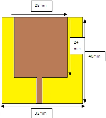
The patch antenna is designed for ultra-wideband frequency range. The width of microstrip line taken as 3 mm and the feed length is 11.25mm. Dimensions of the substrate are 40 mm X 32 mm. The patch is energized electromagnetically using 50 ohm microstrip feed line. The geometry is as shown in the Figure 1. EM simulator software’s used to calculate the return loss (S11) and hence the cut off frequencies
of the antenna.
A rectangular patch antenna is modified with different step size widths (W) and lengths (S) comprising of four steps with dimensions of W1×S1, W2×S2, W3×S3, and W4×S4 to enhance the bandwidth of UWB antenna and to achieve multiband frequencies as shown in Figure2.
[image:2.612.340.526.67.482.2]The geometrical parameters of proposed antenna shown in figure 2 are selected cautiously by running various parameter sweeps and finally the best possible parameters for proposed configuration are obtained as shown in Table 1 in tabular form.
Figure: 1 Rectangular Patch Antenna.
(a)
(b)
Figure: 2 Geometry of proposed Antenna (a) Front View (b) Back View
Table I. Optimal design parameters of the proposed UWB antenna
Size of substrate 32x40mm
Ground plane Size 32x10 mm
Various patch steps of antenna
(A) W1 x S1 (B) W2x S2 (C) W3x S3 (D) W4 x S4
28 x 12 mm 24 x 5.75 mm 12x 5.25mm 8 x 5.75 mm
Length ofFeed Line (Lf) 11.25
Width of Feed Line (Wf) 3 mm
Length and width of notch in ground plane
[image:2.612.103.285.368.571.2]III. NEURAL NETWORK MODEL
The prime objective of this work is to design and optimize the proposed antenna structure The optimized patch structure of the proposed antenna is achieved as a function of input variables, such as thickness of the substrate material (t), permittivity of the material (εrel,)and the resonance frequency (fc), using NN techniques. In the same way, in the study of NN, the resonant frequency of the microstrip antenna is achieved as a function of patch dimensions width (w), length (l), thickness of the material, and permittivity of the material.
The Forward Side of the model:
[image:3.612.326.572.139.306.2]The forward side design consists of inputs like resonant frequency (fc), thickness of substrate (t) and permittivity (εrel) to get the patch dimensions in the form of width (w) and length (l).
Figure 3Forward side of ANN model
The reverse side of model:
In the same way, the using reverse model of NN, the resonant frequency of the microstrip antenna is obtained as the property of patch dimensions (w, l), dielectric material thickness (t) and dielectric constants of the substrate as shown in figure 4.
Figure: 4 Reverse sideANN model
IV. OPTIMIZATION USING NEURAL NETWORK
In this study, the NN is working as a tool in defining the dimensions of proposed micro strip antennas as
[image:3.612.107.260.300.383.2]weights during the training phase is known as back-propagation. Both Radial Basis Function (RBF) and Multilayer Perception (MLP) networks were used in ANN algorithm. RBF networks are used to build ANN model.
Figure 5.ANN model Structure [9]
MLP neural networks are the easiest ANN models, and for that reason most commonly used [7], [8].Further, MLPNNs is trained through the standard back propagation algorithm .It has generally three layers, named as, an input layer, a hidden or intermediate layer and an output layer. The neurons of input layer allocate the input values x j to the hidden layer(s) neurons[9].
Each neuron of hidden layer j adds up its input values xjafter assigning weight to them and thus strengthens the individual connections wjias of the input layer and calculates its output value yias a mathematical function f of the addition:
=f (∑ ) ………..(1)
Where f notationused to represent a hyperbolic or sigmoid tangent function. In the same way neurons of output layer is calculated.
Training an ANN involves the adjustment of weights of the network by means of a learning algorithm. Here, the back propagation learning algorithm [10]is used which is also called the gradient descent algorithm that provides the modification in wij(k) in the form of weighted connection among neurons iand j in this way:
∆ = α + µ∆ (k - 1)………(2)
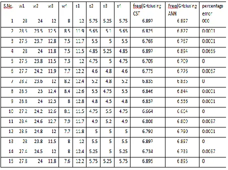
[image:3.612.83.276.486.606.2]In the training of neural network, gradient descent with adaptive learning rate algorithm is used and K-fold cross-validation is used for the test result to be more valuable .This method is used for finding the best ANN structural design. The model developed is trained with data, which is collected by CST Simulation Software. Eight antenna dimensions having different length and width of i.e. w1,w2,w3,w4 are the width and s1,s2,s3,s4 are the length of steps used for proposed antenna. These eight dimensions are diverse from 0.1 to 2 mm and related simulated resonance frequencies are taken with the help of CST software. The sampled values are then scaled within the range 1to -1 and used as the training data for the network. In neural network during training process weights are adjusted automatically a thresh hold values so that there is minimum error between the predicted and sampled value. Back propagation algorithm is used to compute these adjusted values. In this model 100 data samples are worn to design MSA from which details of 15 data samples have been given in Table 2. Mainly three layers are used in algorithm i.e. input layer, hidden layer and output layer. Out of the 100 data generated, 70 are used for training and the rest are used for testing of the trained neural network. The optimized values of different parameters, which are obtained by trial and error for the training of the network, are: (1) the number of input nodes = 3; (2) in the hidden layer, the number of neurons =30; (3) the number of output node = 2; (4).
[image:4.612.324.566.71.275.2]Figure6.Backend model of NN (using Matlab) [9]
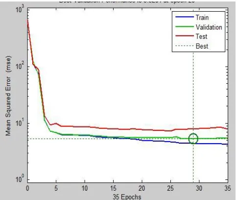
[image:4.612.325.568.310.486.2]Figure 7.Number of epochs to attain minimum means square error level
Figure: 8 Gradient and mu results at epochs 35
The training algorithm used is trainlm. The preferred transfer function is tansig and purelin. The feed forward back propagation network architecture is simulating the antenna design with high efficiency and accuracy. The training and testing result is as shown Table 2. Best validation performance of the network is at epoch 35 as shown in Figure7 and corresponding gradient and mu are shown in Figure8.
Table 2 represents the resonant frequencies obtained by using CST software and the by using Feed-Forward Back Propagation (FFBP) algorithm. The percentage error has been computed as the difference between the value obtained by CST software and the FFBP algorithm and it has been observed that it is very less and close to zero. So the antenna dimensions are well optimized using NN.
V. CONCLUSION
NN is considered as a computational tool in the designing of proposed micro strip antenna in this work. Forward side of the design procedure is the synthesis and the reverse side is the analysis of the design. So the geometric dimensions i.e. width and the length of the patch with high accuracy can be obtained at the output of the synthesis network in terms of height and dielectric constant of the used substrate. At the final stage, design procedure is analyzed; the data attained by move backward the input-output information of the synthesis work is used for determining the parameters of the optimized antenna. The synthesized resonant frequency is compared with the targeted resonant frequency in the analysis ANN. In conclusion, in this research work, a generalize design method for the micro strip antennas is proposed using ANN and this is validated by means of the patch structure.
REFERENCES
[1] Choudhury, B., Thomas, S., &Jha, R. M. (2015). Implementation of soft computing optimization
techniques in antenna engineering [antenna
applications corner]. IEEE Antennas and Propagation Magazine, 57(6), 122-131.
[2] Singhal, M., & Saini, G. (2017). Optimization of antenna parameters using artificial neural network: A review. Int. J. Comput. Trends Technol, 44, 64-73.
based on Artificial Neural Network. In The 8th European Conference on Antennas and Propagation (EuCAP 2014) (pp. 3172-3175). IEEE.
[5] Ozkaya, U., &Seyfi, L. (2015). Dimension optimization of microstrip patch antenna in X/Ku band via artificial neural network. Procedia-Social and Behavioral Sciences, 195, 2520-2526.
[6] Kaur, R., & Rattan, M. (2015). Optimization of the return loss of differentially fed microstrip patch antenna using ANN and firefly algorithm. Wireless Personal Communications, 80(4), 1547-1556. [7] Guney, K., Sagiroglu, S., &Erler, M. (2002).
Generalized neural method to determine resonant
frequencies of various microstrip antennas.
International Journal of RF and Microwave
Computer‐Aided Engineering: Co‐sponsored by the Center for Advanced Manufacturing and Packaging of
Microwave, Optical, and Digital Electronics
(CAMPmode) at the University of Colorado at Boulder, 12(1), 131-139..
[8] Dhaliwal, B. S., &Pattnaik, S. S. (2016). Performance comparison of bio-inspired optimization algorithms for Sierpinski gasket fractal antenna design. Neural Computing and Applications, 27(3), 585-592.. [9] Mishra, R. K., &Patnaik, A. (1998). Neural
network-based CAD model for the design of square-patch antennas. IEEE Transactions on Antennas and propagation, 46(12), 1890-1891.
[10] Devi, S., Panda, D. C., &Pattnaik, S. S. (2002, June). A novel method of using artificial neural networks to calculate input impedance of circular microstrip antenna. In IEEE Antennas and Propagation Society International Symposium (IEEE Cat. No. 02CH37313) (Vol. 3, pp. 462-465). IEEE.
[11] Xiao, L. Y., Shao, W., Jin, F. L., & Wang, B. Z. (2018). Multiparameter modeling with ANN for antenna design. IEEE Transactions on Antennas and Propagation, 66(7), 3718-3723.
[12] Chetioui, M., Boudkhil, A., Benabdallah, N., &Benahmed, N. (2018, April). Design and optimization of SIW patch antenna for Ku band applications using ANN algorithms. In 2018 4th International Conference on Optimization and Applications (ICOA) (pp. 1-4). IEEE.
AUTHOR DETAILS
“Dr. Sukhdeep Kaur is working as Professor in Chandigarh Engineering College, Mohali, India. She did PhD. from Thapar Institute of Engineering and Technology, Punjab, India in the yest 2016. She has more than 18 years of teaching experience, more than 15 national and 20 international journal research papers to her credit. Her area of interest are Wireless Communication and Antenna design.”
[image:5.612.77.305.77.247.2]Presently, he is working as Professor in ECED at Thapar Institute of Engineering and Technology, Patiala, Punjab, India. He has published 80 papers in National and International journals/ Conferences. He has worth Rs 1.5 crore projects to his credit. His main research interest includes antennas, Wireless Communication, MIMO, and FFT.”
Dr. Pooja Sahni is working as Professor in Chandigarh Engineering College, Mohali, India. She has more than 15 years of teaching experience, more than 11 national and 16 international journal research papers to his credit and filed five patents. Her area of interest is Wireless Communication
![Figure 5.ANN model Structure [9]](https://thumb-us.123doks.com/thumbv2/123dok_us/8192745.258457/3.612.83.276.486.606/figure-ann-model-structure.webp)