UNIVERSITI TEKNIKAL MALAYSIA MELAKA
THE INFLUENCE OF REFRIGERANT CHARGING FOR
NON-DUCTED SPLIT UNIT 1 HORSEPOWER
AIR-CONDITIONING SYSTEM
This report is submitted in accordance with the requirement of the University Technical Malaysia Melaka (UTeM) for the Bachelor’s Degree in Mechanical Engineering Technology (Refrigerant and Air Conditioning system with hons)
by
MUHAMMAD FAIZ BIN AZMAN B071410143
921014-03-5199
UNIVERSITI TEKNIKAL MALAYSIA MELAKA
BORANG PENGESAHAN STATUS LAPORAN PROJEK SARJANA MUDA
TAJUK: THE INFLUENCE OF REFRIGERANT CHARGING FOR NON-DUCTED SPLIT UNIT 1 HORSEPOWER AIR-CONDITIONING SYSTEM
SESI PENGAJIAN: 2017/18 Semester 1 Saya MUHAMMAD FAIZ BIN AZMAN
mengaku membenarkan Laporan PSM ini disimpan di Perpustakaan Universiti Teknikal Malaysia Melaka (UTeM) dengan syarat-syarat kegunaan seperti berikut:
1. Laporan PSM adalah hak milik Universiti Teknikal Malaysia Melaka dan penulis. 2. Perpustakaan Universiti Teknikal Malaysia Melaka dibenarkan membuat salinan
untuk tujuan pengajian sahaja dengan izin penulis.
3. Perpustakaan dibenarkan membuat salinan laporan PSM ini sebagai bahan pertukaran antara institusi pengajian tinggi.
4. **Sila tandakan ( )
SULIT
TERHAD
TIDAK TERHAD
(Mengandungi maklumat yang berdarjah keselamatan atau kepentingan Malaysia sebagaimana yang termaktub dalam AKTA RAHSIA RASMI 1972)
(Mengandungi maklumat TERHAD yang telah ditentukan oleh organisasi/badan di mana penyelidikan dijalankan)
Alamat Tetap:
NO.6 Jalan Bayan 9 Taman Bukit Katil
75450 Ayer Keroh,
Melaka.
Tarikh: ________________________
Disahkan oleh:
Cop Rasmi:
i
DECLARATION
I hereby, declared this report entitled ‘The influence of refrigerant charging for non-ducted split unit 1 horsepower air conditioning system’ is the result of my own
research except as cited in references.
Signature :………
ii
APPROVAL
This report is submitted to the faculty of Engineering technology of UTeM as a Partial fulfilment of the requirements for the degree of Bachelor of Engineering Technology (Refrigerant and Air Conditioning System with Hons) This Member of the Supervisory is as follow:
iii
ABSTRACT
iv
ABSTRAK
Sistem penyejuk dan penyaman udara unit pemisah digunakan secara meluas melalui
pasaran di dunia. Penyelenggaraan yang tidak betul akan menyebabkan sistem
pengecasan berlebihan dan berkurangan. Sistem penyejukan tidak boleh mencapai
tahap yang efisyen dan kapitsiti penyejukan. Sistem penyaman udaran seharusnya di
cas dengan tahap optimum untuk berkerja dengan tahap tertinggi. Selain itu,
menjalankan sistem dengan lebihan bahan penyejukakan akan mengurangkan jangka
hayat sistem. Projek ini mengunakan unit pemisah tanpa saluran penyaman udara
jenis penyongsang R410A dan bukan penyongsang R22 1 kuasa kuda. Projek ini
menujukkan perbandingan aliran elektrik, suhu, kapisiti penyejukan dan prestasi
sistem. Keputusan menunjukkan bahawa pengecasan penyejukan berlebihan dan
berkurangan untuk kedua dua sistem tidak boleh mencapai tahap prestasi. Tambahan
pula, pengecasan paling teruk ialah pengecasan berlebihan dimana sistem
memerlukan lebihan kuasa elektrik untuk memampatkan penyejukan. Projek ini
mentakrifkan bahawa pengecasan yang betul penyaman udara boleh melindungi
sistem dan menjimatkan tenaga. Jumlah yang betul bahan pendingin dalam sistem
penyaman udara adalah penting untuk memberi prestasi penuh dan ianya boleh
v
DEDICATION
vi
ACKNOWLEDGEMENT
vii
TABLE OF CONTENTS
Abstract i
Abstrak ii
Dedication iii
Acknowledgement iv
Table of Content v
List of table vii
List of figure viii
List of Abbreviations ix
CHAPTER 1: INTRODUCTION 1.0 Introduction ... 1
1.1 Background Study ... 1
1.2 Problem Statement ... 2
1.3 Objective ... 2
1.4 Work Scope ... 3
1.5 Summary ... 3
2.0 Introduction ... 4
2.1 Building Consumption ... 5
2.2 Non-Ducted Air Conditioning System ... 6
2.3 Wall Mounted ... 9
2.3.1 Compressor ... 10
2.3.2 Condenser ... 11
2.3.3 Expansion Valve ... 11
2.3.4 Evaporator ... 12
viii
2.5 Undercharge ... 13
2.6 Overcharges ... 14
2.7 Refrigerant ... 14
2.8 Effect of Environment ... 16
2.8.1 Chronic Health Effect ... 18
2.8.2 Ozone Depletion Potential ... 18
2.8.3 Global Warming Potential ... 19
2.9 Mollier Chart ... 20
2.10 Summary ... 21
3.0 Introduction ... 22
3.1 Process Development Project ... 23
3.2 Data Collection ... 24
3.2.1 Temperature selection ... 25
3.2.2 Moiller Chart ... 26
3.3 Procedure ... 30
3.3.1 Operating Procedure... 30
3.3.2 Material and Equipment ... 32
3.4 Summary ... 35
4.0 Introduction ... 36
4.1 Data Collection Non-Inverter ... 37
4.2 Data Collection Inverter ... 41
4.3 Comparison Inverter and Non-Inverter ... 46
5.0 Introduction ... 49
5.1 Summary of the Project ... 49
5.2 Achievement of Project Objective ... 50
ix
LIST OF TABLE
Table2.1: Types of split unit system 7
Table2.2 : The effect of refrigerant usage 17
Table3. 1 : The data collection 24
Table3. 2: Material and Equipment 32
Table 4.1: The fixed experimental variable and measured parameter 36 Table 4.2: The data collection for non-inverter with refrigerant R22 37
Table 4.3: Result of analysis and calculation for R22 39
Table 4.4: The data collection for inverter with refrigerant R410A 42
Table 4.5: The analysis and calculation for R410A 44
x
LIST OF FIGURES
Figure2.1: Total energy consumption 5
Figure2.2 : Total Residential Energy 6
Figure2.3: Refrigeration Cycle 9
Figure2.4 : Mollier Chart 20
Figure3.1: Research Flowchart 23
Figure3.2 :Location thermocouple 26
Figure3.3: Temperature selection at the mollier chart 27
Figure3.4: R410A and R22 mollier chart 27
Figure3.5: The EER for non-inverter R22 29
Figure3.6: The EER for inverter R410A 29
Figure3.7: The experimental set up point thermocouple 31
Figure3.8: The operating procedure 31
Figure 3.9: The process to insert refrigerant 32
Figure4.1: The mollier chart R22 with pressure 60Psi 38
Figure4.2: The coefficient of performance versus refrigerant pressure R22 40
Figure4.3: Current flow versus refrigerant pressure 41
xi
LIST OF ABBREVIATIONS, SYMBOLS AND
NOMENCLATURE
AC – Air Conditioning
COP – Coefficient of Performance EER – Energy Efficiency Ratio
HVAC – Heating Ventilation Air Conditioning HFC – Hydro Fluorocarbon
HCFC – hydrochlorofluorocarbon CFC – Chloroflorocarbon
Hp – Horsepower
R – Refrigerant
CH4 – Methane
1
CHAPTER 1
INTRODUCTION
1.0 Introduction
The air conditioning split unit system is the system that needed the specific pressure that can produce the required thermal comfort for human and to prevent the waste electric consumption. The detail in chapter 1 is background study, problem statement, objective and work scope.
1.1 Background Study
2 things like air conditioners, refrigerators and containers use something called chlorofluorocarbons (CFCs). These substances are heavier than air, but over time they are carried high into the stratosphere by wind action.
1.2 Problem Statement
Improper amounts of refrigerant either the overcharge or undercharge refrigerant are classified as improper maintenance. The refrigerant cannot achieve their rated efficiency and cooling capacity for the system. Therefore, the system will unbalance because of low or high refrigerant charges. When the refrigerant is low, the cooling capacity in the system is low causes the piping getting frost. Meanwhile, for overcharge, the current and temperature for the system will rose up because of effect the over amount of gas refrigerant. Furthermore, running the system at low or high refrigerant charges level may reduce the lifespan air-conditioning. Mostly the system is designed to protect the main component such as compressor, condenser, expansion valve and evaporator which to make the system low maintenance. However, if the system operated with high refrigerant charges, it will decrease the life expectancy components because the system will push to the limit until the control of system cut off by their own to protect the system. The effect for both the low or high amount of refrigerant significantly affect the required thermal comfort because the system not achieve the efficiency required.
1.3 Objective
These studies embark several objectives:
• To study the impact of refrigerant charge level on cooling capacity in the system for R22 and R410A
3 1.4 Work Scope
This project will use split unit non-ducted (wall mounted) air-conditioning inverter unit and non-inverter unit 1 horsepower Panasonic by using refrigerant R22 and R410A.This project aim to measure the running amp, temperature, refrigerant capacity, different pressure between suction and discharge while the system is running. The thickness for copper pipe is 0.61 mm.
There have several limitations for this project:
The piping length for the system is 2 meters.
The environment temperature dry bulb temp and wet bulb temperature is
measure 24ᴼc.
The different system between inverter and non-inverter such as the refrigerant
volume, capacity, maximum amp and control system are measure through the experiment.
1.5 Summary
4
CHAPTER 2
LITERATURE REVIEW
2.0 Introduction
5 2.1 Building Consumption
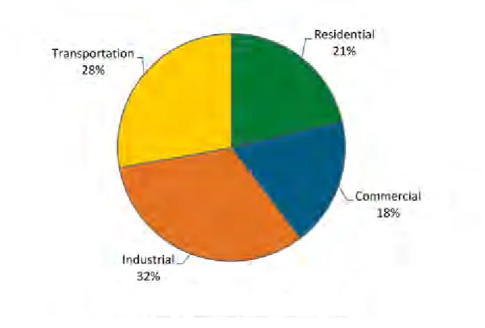
[image:18.595.147.496.380.616.2]Last few decades, Malaysia is the countries as the population and the energy consumption in the country tremendously increased for most of the developing. Besides that, Malaysia is the countries experience rapid urbanization and population growth. Occupants of the buildings manipulate ad interact with their environment and structures to obtain the maximum satisfaction requirement. Especially for thermal comfort on buildings that contribution on energy consumption and carbon dioxide emission (Balubaid et al., 2015). Air conditioning has become a very common part in a life. All place need the air conditioning to provide the requirement thermal comfort or for industries use. There have several demands on air conditioning such as resident, commercial, industries and transportation. Thus, using the air conditioning system need a lot of energy to archives the cooling capacity.
Figure2.1: Total energy consumption
6 air conditioning, in multifamily residential buildings used energy consumption for heating and cooling is become large impact. According to (Goetzler et al., 2013) the total energy consumed 96.1 quadrillion Btu at U.S in 2012.
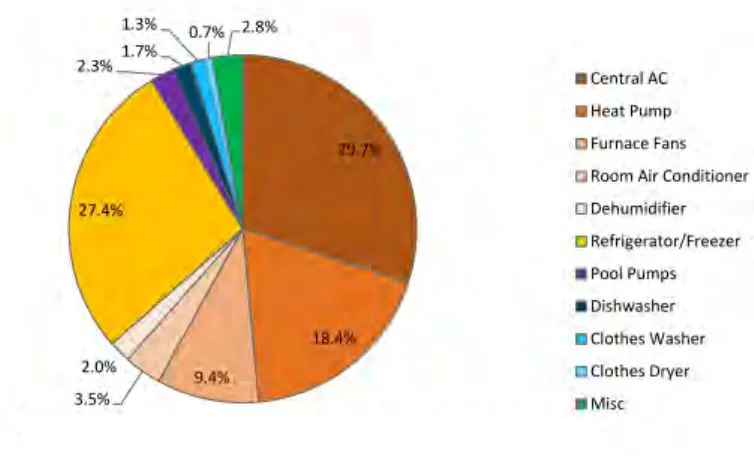
Figure2.2 : Total Residential Energy
Figure 2.2 show that the residential consume 4.73 quadrillion. These reports focus on residential user because at heating, ventilation and air conditioning (HVAC) are the highest energy consumer. Besides, for room air conditioning it consumed of energy is 3.5% and the higher is refrigerant, it uses 27.4% energy consumption. Air conditioning has become a necessity in most modern office building, retail space, house and ware housing.
2.2 Non-Ducted Air Conditioning System
7 or commercial space. Ductless system no need requires ducting like central air conditioners. These systems have two basic parts which is a large condenser unit that installs outdoors and one or more compact wall-mountable blower units that are placed strategically inside the space or zones. When installed, insulated conduit housing the refrigeration lines runs from the outside condenser unit to the blower system indoors. Each wall-mounted blower system can be controlled independently to provide comfortable room cooling right where you need it. Air conditioning comes in many forms. Commercial air conditioning system can be either of these too, but larger system. The selection of the system is depending on design, application, installation, maintenance and cost.
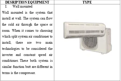
Table 2.1: Types of split unit system
DESRIPTION EQUIPMENT TYPE
I. Wall mounted
8 II. Floor mounted
Floor mounted can look more discreet that their wall mounted alternative. It can minimize the impact in a room aesthetics. Usually floor mounted are installed large space like mosque.
III. Ceiling mounted
• Exposed type
Exposed type can provide air floor up to long distance around 8 meter. It mounted near a wall and just below the ceiling height.
• Hideaway type
Usually these types are installed at hotel room. The indoor type is hiding between wall and ceiling to give a special decor for the best design.
• Cassette type
9 different direction. It can cover the
fairly large room.
IV. Window and portable These units fit directly inside the window and readily to give wide range air flow. This type is easy to install, low initial cost and portable. It can change to other room with less procedure.
2.3 Wall Mounted
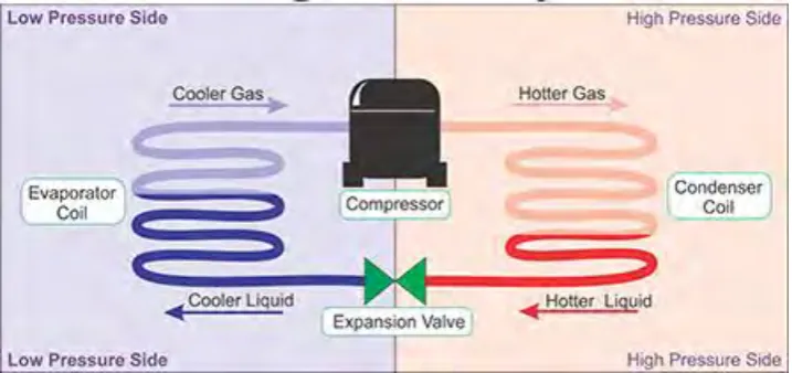
[image:22.595.116.524.69.260.2]The air conditioning system is the system that always change the phase or temperature to another place. The phase is recycled from liquid to gas. The temperature is transfer from hot to cold place.
Figure 2.3: Refrigeration Cycle
[image:22.595.141.500.440.609.2]10 valve, the refrigerant is change the temperature from high temperature to low temperature. The low pressure and low temperature at liquid phase, the evaporator changes the phase for liquid to vapour. The cycle is rotate until the system cut off. Air conditioning have four basic components which is:
1) Compressor 2) Condenser 3) Expansion valve 4) Evaporator
2.3.1 Compressor
11 2.3.2 Condenser
Heat from refrigerant is transferred to the cooling fluid. Refrigerant condenses to liquid. Condenseris is a tool that to remove heat from the refrigerator gas that is absorbed from evaporator. The heat from refrigerator gas will flow through the condenser walls to condenser medium. The refrigerator gas will be cooling and condense (Elsherbini & Maheshwari, 2010). Usually the wall mounted use finned and tube condenser. Fin and tube using the force air convection, the refrigerant circulates through a coil and air flows across the outside of the tubing. Plus,the air motion caused by natural convection effects when the air is heated or the condenser can include a fan to increase air flow rate. The fin and tube utilize small space. Can saving a cost because the initial installation and maintaining the condenser is easy compare to chilled system.
2.3.3 Expansion Valve