This is a repository copy of
Michell structure for a uniform load over multiple spans
.
White Rose Research Online URL for this paper:
http://eprints.whiterose.ac.uk/77140/
Proceedings Paper:
Pichugin, A.V., Tyas, A. and Gilbert, M. (2011) Michell structure for a uniform load over
multiple spans. In: 9th World Congress on Structural & Multidisciplinary Optimization. 9th
World Congress on Structural and Multidisciplinary Optimization, June 13 - 17, 2011,
Shizuoka, Japan. .
[email protected] https://eprints.whiterose.ac.uk/
Reuse
Unless indicated otherwise, fulltext items are protected by copyright with all rights reserved. The copyright exception in section 29 of the Copyright, Designs and Patents Act 1988 allows the making of a single copy solely for the purpose of non-commercial research or private study within the limits of fair dealing. The publisher or other rights-holder may allow further reproduction and re-use of this version - refer to the White Rose Research Online record for this item. Where records identify the publisher as the copyright holder, users can verify any specific terms of use on the publisher’s website.
Takedown
If you consider content in White Rose Research Online to be in breach of UK law, please notify us by
9th
World Congress on Structural and Multidisciplinary Optimization June 13 - 17, 2011, Shizuoka, Japan
Michell structure for a uniform load over multiple spans
Aleksey V. Pichugin1
, Andrew Tyas2
, Matthew Gilbert3
1
Brunel University, Uxbridge, UK, [email protected]
2
University of Sheffield, Sheffield, UK, [email protected]
3
University of Sheffield, Sheffield, UK, [email protected]
Abstract
A new half-plane Michell structure capable of carrying a uniformly distributed load of infinite horizon-tal extent over a series of equally-spaced pinned supports is presented. For the case of equal allowable stresses in tension and compression a full kinematic description of the structure is provided. Although formal proof of optimality of the solution presented is not yet available, the proposed analytical solution is supported by available numerical evidence. Numerical solutions for cases of unequal allowable stresses are also presented, and suggest the existence of a wider family of related, simple, and practically relevant structures, which range in form from an arch with vertical hangers to a cable-stayed bridge.
Keywords: Michell structure, uniformly distributed loading.
1. Introduction
In his groundbreaking contribution to the field of structural optimization [11], A. G. M. Michell formulated the criteria to be satisfied by all least-volume trusses with equal tensile and compressive yield stresses, see also [6, 12]. In trusses satisfying these criteria the magnitudes of the tensile and/or compressive stresses in load-carrying members must everywhere be at maximum allowable values and the virtual strains in such members must not exceed these limiting values. The displacement field must remain continuous throughout the design domain and satisfy the kinematic restrictions imposed on the solution.
Michell’s criteria can be satisfied in several different ways, implying that every optimal structure can be split into one or several regions, distinguished by values of the member force componentsf′ andf′′:
T : f′ <0, f′′>0, ε′=−ϵ, ε′′=ϵ; (1)
RC: f′ = 0 f′′<0, |ε′|6ϵ, ε′′=−ϵ; (2)
RT : f′ >0, f′′= 0, ε′=ϵ, |ε′′|6ϵ . (3)
Within (1)–(3), ε′ and ε′′ denote principal strains and ϵ is the positive infinitesimal. Optimal trusses may also contain regions of uniform tension and/or uniform compression [15]. All trusses constructed by Michell [11], as well as the majority of optimal trusses identified in the early literature, only feature one or several regions of type T; the term ‘Michell structure’ is therefore sometimes considered to be synonymous with (1). However in this paper we use this term to describe any structure that satisfies the Michell criteria, and any number of regions (1)–(3) can be present.
The deceptive simplicity of the specified criteria should not obscure the fact that there is no known procedure for verifying whether a Michell structure exists for a given problem definition, or for determining its form. Unsurprisingly, the number of Michell structures to have been identified to date is not large, see e.g. [1, 2, 6, 8–11, 14]. Furthermore, whilst some notable exceptions exist [3, 7, 16, 17], the majority of known Michell structures are designed to support only a single external point load.
L/2 L/2
x y
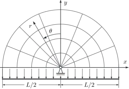
[image:3.595.198.407.71.216.2]r θ
Figure 1: The Michell half-wheel subjected to a uniformly distributed load.
paper appear to support our claim. We also present a number of numerical solutions for similar problems with unequal allowable stresses, suggesting that a wider family of related, simple and practically relevant structures exists.
2. An auxiliary problem
Before analysing our main problem, featuring an infinite number of equally-spaced supports, it is instruc-tive to examine a simpler set-up. Consider a uniformly distributed load (wper unit length) that is applied to a horizontal line segment of lengthL, and needs to be transmitted to a pinned support at the centre of the segment. It is not difficult to verify that the suitable optimal solution for the upper half-plane is a ‘half-wheel’, the structure comprising concentric semicircles and orthogonal radii, as shown on Fig. 1. Very similar structures for problems involving external point loads have been considered in [6, 11]. The structure is conveniently mapped by the orthogonal curvilinear system (α, β), such that
α=r , β =θ , ϕ=β+π
2, A= 1, B=α , (4)
where r, 0 6 r 6 L/2, is the linear distance from the support, θ, −π/2 6 θ 6 π/2, the polar angle measured counter-clockwise from the vertical symmetry axis andϕthe angle measured from the horizontal line to the tangent of anα-line. FunctionsAandB are the components of the metric tensor. A suitable strain field is given by
u=−ϵα , v= 2ϵαβ , ω= 2ϵβ , (5)
in whichuandv denote displacements alongαandβ, respectively, andω denotes the rotation.
If T′ and T′′ denote the end loads per unit coordinate difference in the α and β directions, then they must satisfy the standard equilibrium equations in curvilinear coordinates:
∂T′
∂α =T
′′∂ϕ
∂β, ∂T′′
∂β =−T
′∂ϕ
∂α, (6)
see [6]. In our case ∂T′′/∂β = 0, and the equilibrium of vertical components of forces acting along the bottom of the structure requires that T′′ = w. Equation (6)1 can now be integrated, yielding
T′=wα+t′(β). One needs to add another boundary condition to fully specify the force field within the structure. For example, ifT′is required to vanish along the outer rim of the structure, thent′(β) =−wL/2 and T′ =w(α−L/2), hence, completing the solution. The volume of the resulting structure is easily found from the virtual work of external forces, which in our particular case yields
Waux = σϵ2
∫ L/2
0 −
wv|β=−π/2dα=
π 4
wL2
σ . (7)
3. The virtual displacement field
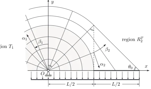
copies of field (5), expanding from each of the supports, then this would be found to be impossible due to the monotonic variation of each localuandv as functions of localα. Motivated by this observation, we consider an extension of the structure from Section 2, a half-span as shown in Fig. 2 (we assume that the other half is obtained by reflecting the structure about the verticalOy). The original half-wheel, shaded in the new drawing, is expanded to the radius L/√2 and then cut along the vertical lines originating from points x=±L/2 in the global Cartesian coordinate systemOxy. Tensile circumferential members of the original half-wheel are then continued tangentially, as straight ties that connect the points along the cuts to horizontal compression members atL/26|x|6L. These concentrated members are needed to rotate the tie forces and equilibrate the portions of external load that are uniformly distributed along L/26|x|6L.
O α1
β1
α2
β2
L/2 L/2
x y
regionT1
regionRT
2
[image:4.595.144.448.208.388.2]θ0
Figure 2: Half-span of the proposed structure.
The description of this structure requires the use of several curvilinear coordinate systems. The part of the structure for−L/2 6x6L/2, termed regionT1, can be fully described using the same coordinate
system as in Section 2. Thus, we assume that α1,β1, ϕ1,A1, B1,u1, v1 andω1 are defined precisely as
in (4) and (6)∗. The only difference concerns the ranges of variation of the coordinates; since the verticals
x=±L/2 are described within regionT1 by equationα1=L/2|sinβ1|, therefore, −π/26β16π/2 (as
before) and 06α16min{L/ √
2, L/2|sinβ1|}. In particular, the curvilinear displacements and rotation
are given along the boundary with regionRT
2 by
u1=
ϵL 2 sinβ1
, v1=−
ϵβ1L
sinβ1
, ω1= 2ϵβ1, at x=
L
2 . (8)
The curvilinear coordinate system appropriate for describing the strain field within regionRT
2 is harder
to formulate. The systems of straight, non-intersecting ties are associated with regions described by (3); the mathematical formalism describing such regions is presented in [6, Sect. 4.2]. We begin by defining coordinateβ2 as the same polar angle as the one used within region T1. The bottom left corner ofRT2
corresponds to β2 =−π/2, whereas the uppermost tie corresponds to β2 =−π/4. More generally, all
ties withinRT
2 belong to the family of straight lines parametrised byβ2:
2x−2ycotβ2−L(1 + cot 2
β2) = 0. (9)
It is possible to show that these lines envelop an evolute with the equation
y2
+ 2Lx−L2
= 0. (10)
In an orthogonal coordinate system withα2 defined as the distance from a fixed involute, equation (10)
may be alternatively written asα2+F(β2) = 0. HereF(β2) is an arc length measured along the evolute
from the point whereα2= 0. Since evolute (10) touches the bottom left corner of RT2, it is convenient
to use the involute passing through this point as the coordinate axis. We can now integrate along the evolute to obtain the full description of our curvilinear coordinates in the form
ϕ2=β2+
π
2, A2= 1, B2=α2+F(β2), where F(β2) = L
2(cotβ2cscβ2−ln[cotβ2−cscβ2]), (11)
see also [6]. The Cartesian description of coordinate lines in (α2, β2) is obtained by computing
x+ iy= L 2 +α2e
iβ2+ i∫ −π/
4
−π/2
eiξF(ξ) dξ , (12)
which leads to the explicit formulae
x= (α2−Lln[cotβ2−cscβ2]/2) cosβ2+L/2, (13)
y= (α2−Lln[cotβ2−cscβ2]/2) sinβ2−Lcotβ2/2. (14)
An additional test of the validity of these equations may be performed by directly computing the metric tensor components from (13) and (14). The resulting expressions match equations (11) exactly. Table 1 presents some useful relationships between coordinates of various lines and points within the global Cartesian and the local curvilinear coordinate systems.
Table 1: Significant lines and points within the coordinate system (α2, β2).
Cartesian Curvilinear Significance
x=L/2 α2=Lln(cotβ2−cscβ2)/2 the boundary betweenT1 andRT2
y= 0 α2=L(cotβ2cscβ2+ ln[cotβ2−cscβ2])/2 the bottom ofRT2
y=L−x β2=−π/4 the top tie ofR2T
(L/2,0) (0,−π/2) the bottom left corner ofRT
2
(L/2, L/2) (Lln(√2−1)/2,−π/4) the top left corner ofRT
2
(L,0) (L[√2 + ln(√2−1)]/2,−π/4) the right corner ofRT
2
Given orthogonal coordinates (11), we can formulate the system of partial differential equations describing principal and shear strains, as well as the rotation, in the form:
∂u2
∂α2
=ϵ , v2=ω2(α2+F(β2)) +
∂u2
∂β2
, (15)
ω2=
∂v2
∂α2
, ε′′
2= (α2+F(β2))− 1
(∂v
2
∂β2
+u2
)
. (16)
Equation (15)1 implies that u2 =ϵ(α2+G(β2)), withG(β2) chosen to ensure the continuity along the
linex=L/2. Sinceβ1 andβ2 denote the same angle, the continuity with circumferential displacements
requiresu2|β
2=β1 =−v1|β1=β2, so that a reference to (8)2 leads to the full definition
u2=ϵ(α2+G(β2)), G(β2) =F(β2) +L(2β2−cotβ2) cscβ2/2. (17)
The rotation is fixed alongα2-lines withinRT2; therefore, the continuity of rotation along x=L/2 and
equation (8)3 giveω2= 2ϵβ2. This enables us to compute u2 directly from (15)2, with the result
v2=ϵ(2β2[α2+F(β2)]−L[2β2cotβ2−1] cscβ2/2). (18)
The substitution of displacement (18) into (16)1 again gives ω2 = 2ϵβ2, as it should. By substituting
the value for α2 associated with x = L/2 from Table 1 into (18), it is also possible to verify that
v2|β2=β1=u1|β1=β2. The only remaining equation (16)2provides a direct mean for computing the strain
alongβ2-lines, which is found to be
ε′′ 2 = 2ϵ
(
2−Lαcotβ2cscβ2 2+F(β2)
)
L/2 L 3L/2 L
√
2
L
√
[image:6.595.119.486.73.216.2]2
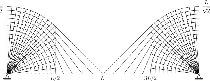
Figure 3: A single span of the proposed optimum structure.
For the field within RT
2 to satisfy the Michell criteria (3), we must ensure that |ε′′2| 6 ϵ. It is worth
reminding ourselves that the denominator within (19) is an equation of the evolute. It can only vanish in a single point of regionRT
2, where the evolute touches the bottom left corner, see (10). However, due
to the cancellation of terms, one has everywhere along the bottom boundary ofRT
2:
ε′′
2|y=0 =ϵ , (20)
see (19) and Table 1. Simultaneously, everywhere along the boundary between regionsT1andRT2,
ε′′
2|x=L/2=−ϵ . (21)
Keeping in mind that, for every fixedβ2, ε′′2 is a monotonously increasing function ofα2, see (19), that
changes from −ϵ at x = L/2 to ϵ at y = 0, we come to the sought-for conclusion that RT
2 is a valid
Michell region of typeRT, see (3).
Having constructed a consistent strain field for a single half-span does not yet solve the original problem, featuring infinite sequence of equally-spaced level supports. A full span of length 2Lcan be obtained by reflecting the constructed fields with respect to Oy. In addition, we can use equations (17), (18) and Table 1 to writeux
2, the horizontal component of displacement alongy= 0, in the form
ux2|y=0≡u2|y=0sinϕ2+v2|y=0cosϕ2=−ϵ
Lcos 2β2
2 sin2
β2
. (22)
Clearly, this vanishes whenβ2=−π/4, i.e. whenx=L. This means that we can also reflect the resulting
structure with respect to the vertical line x =L. Therefore, it is now possible to produce a structure that, via a series of simple reflections, spans across an infinite sequence of level supports placed 2Lapart alongOx. An illustration of a single span of such a structure is given in Fig. 3.
It has already been mentioned that regions of typeT, i.e. the regions that satisfy the Michell criteria and conditions (1), are often perceived to be synonymous with all Michell structures. Since these regions fea-ture systems of mutually orthogonal members, the requirement of member orthogonality often presumed for general Michell structures. This requirement is, evidently, violated at the bottom boundary of region RT
2. Nevertheless, Rozvany [13] shows that the orthogonality requirement can be relaxed along
bound-aries betweenRCandRT regions. Thus, we can resolve the contradiction by interpreting the compression bar along the bottom ofRT
2 as a degenerate regionRC3, which satisfies all of the conditions (2).
The presence of a compressive concentrated member RC
3 also resolves what may appear to be a strain
discontinuity at Cartesian point (L/2,0). Without RC
3, the horizontal strain along the bottom of T1
would be compressive, whereas the normal strain along the bottom ofRT
2, which becomes horizontal at
x= L/2, would be tensile, see (20). Thus, the compressive member RC
3 ensures the continuity of the
strain field aty= 0.
4. The volume of the structure
The volume of a single span of the proposed structure can be computed by calculating the work done by the external forces and dividing it by ϵσ. The work WI done by the distributed load acting along
−L/26x6L/2 has already been computed in (7): WI ≡ϵσWaux =ϵπwL2/4. In order to determine the work WII, done by the distributed load acting along L/26|x| 6L, one needs to find the vertical displacementuy2 along the bottom boundary ofRT2. Using equations (17), (18) and Table 1, we obtain
uy2|y=0≡ −u2|y=0cosϕ2+v2|y=0sinϕ2=ϵL(β2csc 2
β2+ cotβ2). (23)
With the help of (23), the work integral is computed as
WII = 2
∫ L
L/2
−wuy2|y=0dx= 2wL
∫ −π/4
−π/2
uy2|y=0(cot 2
β2+ 1) cotβ2dβ2=ϵ
(4
3 + π 4
)
wL2
. (24)
It is now self-evident that
Wmin = WI +WII
ϵσ =
(
4 3+
π 2
)
wL2
σ ≈2.90413 wL2
σ . (25)
Therefore, the volume of a single span of the described structure is 11.0% lower than the volume of a simple parabolic arch with vertical hangers, and 7.86% lower than that of the classical solution obtained by Hemp [7], which is known to be sub-optimal (see also [3]).
The solutions for force fields within regionsT1,RT2 andRC3 can be computed without much difficulty and
are omitted here for the sake of brevity. We used these solutions to compute the volume of the structure directly, and to verify formula (25). The volumes obtained via primal and dual formulations matched, therefore providing further confirmation of the correctness of the reported result.
5. Numerical solutions
In order to verify the optimality of the structure described in previous sections, a numerical solution has also been obtained using an efficient numerical layout optimisation procedure [5]. The same procedure was recently used to provide compelling numerical evidence that the parabolic arch is not an optimal structure to transfer a uniformly distributed transmissible load to two pinned supports [4]; see also subsequent formal proof of this [17].
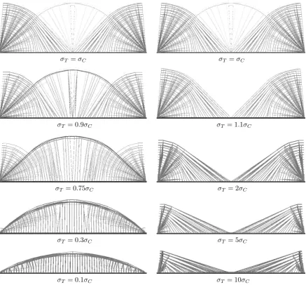
The numerical solutions presented in this paper were computed for several combinations of allowable stresses, using numerical discretizations comprising 61 nodal points in the x direction and 41 nodal points in they direction, therefore optimising over 3,126,250 potential members. The computations, in each of the cases, took around 30 seconds of CPU time on a modern PC. The plots of resulting solutions are grouped together in Fig. 4. Note that the solutions are plotted using a perspective projection, which makes the upper parts of structures appear narrower than they are.
Let σT and σC be the tensile and compressive yield stresses, respectively. The structure obtained in the case when σC =σT and shown (twice) at the top of Fig. 4, displays a remarkable similarity to the analytical solution shown in Fig. 3. However, a slight mismatch in the positions of nodes at the top of Region 2 leads to the appearance of an additional (feint) fan region, comprising straight lines and concentric circles. Supplementary runs were performed to ensure that this vanishes as the numerical discretization is refined.
Interestingly, the numerical solutions for unequal allowable stresses indicate that our solution, although seemingly unusual, is closely related to two well known classes of structure, widely used in engineering practice. In particular, the left hand side of Fig. 4 presents structures dominated by compression (σC > σT). AsσC/σT increases, the fans around the supports shrink in size, with the overall structure tending towards a simple arch with vertical hangers. In the case of structures dominated by tension (σC< σT), shown on the right hand side of Fig. 4, the solutions metamorphose into a cable stayed bridge structure, with the fans shrinking to become stocky, near-vertical, towers.
Closer inspection of the optimal structures dominated by tension enables fairly accurate determination of numerical values of the abscissas at which half-wheel fields are replaced by systems of straight tension members. This allows us to formulate a conjecture about the structures of this type. IfX denotes an abscissa where the described transition takes place, it appears that
X = σC
σT = 0.1σC σT = 0.3σC σT = 0.75σC
σT = 0.9σC σT =σC
σT = 10σC σT = 5σC σT = 2σC σT = 1.1σC
[image:8.595.85.523.69.475.2]σT =σC
Figure 4: The numerical solutions that illustrate the effects of having unequal allowable stresses.
In particular, in the case when σC = σT, (26) yields X =L/2, precisely the same as assumed in our earlier derivations. Expression (26) can also be reformulated in terms of slopeθ0 of the top tie within
regionRT
2, see Fig. 2. A simple geometric argument leads then to the following conclusion
θ0= arctan
√σC
σT , (27)
which is precisely the same condition as the one previously obtained for the parabolic funicular loaded by a transmissible, uniformly distributed load, see [4, 18].
6. Conclusions
Details of a new half-plane Michell structure capable of carrying a uniformly distributed load of infinite horizontal extent over a series of equally-spaced pinned supports have been presented. Although formal proof of optimality of the structure has not yet been demonstrated, the proposed analytical solution is supported by available numerical evidence. Numerical solutions also suggest the existence of a wider fam-ily of related, simple, and practically relevant structures, which range in form from an arch with vertical hangers to a cable-stayed bridge, depending on the specified ratio of limiting compressive to tensile stress.
7. References
[2] H. S. Y. Chan, Half-plane slip-line fields and Michell structures,Quarterly Journal of Mechanics and Applied Mathematics, 20 (4), 453–469, 1967.
[3] H. S. Y. Chan, Symmetric plane frameworks of least weight, in A. Sawczuk and Z. M´roz (Eds.),
Optimization in Structural Design, 313–326, Springer, Berlin, 1975.
[4] W. Darwich, M. Gilbert and A. Tyas, Optimum structure to carry a uniform load between pinned supports,Structural and Multidisciplinary Optimisation, 42 (1), 33–42, 2010.
[5] M. Gilbert and A. Tyas, Layout optimization of large-scale pin-jointed frames,Engineering Compu-tations, 20 (8), 1044–1064, 2003.
[6] W. S. Hemp,Optimum Structures, Clarendon Press, Oxford, 1973.
[7] W. S. Hemp, Michell framework for uniform load between fixed supports,Engineering Optimization, 1(1), 61–69, 1974.
[8] T. Lewi´nski and G. I. N. Rozvany, Exact analytical solutions for some popular benchmark prob-lems in topology optimization II: three-sided polygonal supports, Structural and Multidisciplinary Optimization, 33 (4), 337–349, 2007.
[9] T. Lewi´nski and G. I. N. Rozvany, Exact analytical solutions for some popular benchmark problems in topology optimization III: L-shaped domains,Structural and Multidisciplinary Optimization, 35 (2), 165–174, 2008.
[10] T. Lewi´nski, M. Zhou and G. I. N. Rozvany, Extended exact solutions for least-weight truss layouts— Part I: cantilever with a horizontal axis of symmetry,International Journal of Mechanical Sciences, 36 (5), 375–398, 1994.
[11] A. G. M. Michell, The limits of economy of material in frame-structures, Philosophical Magazine, 8 (47), 589–597, 1904.
[12] G. I. N. Rozvany, Some shortcomings in Michell’s truss theory, Structural Optimization, 12 (4), 244–250, 1996.
[13] G. I. N. Rozvany, Partial relaxation of the orthogonality requirement for classical Michell trusses,
Structural and Multidisciplinary Optimization, 13 (4), 271–274, 1997.
[14] G. I. N. Rozvany, Exact analytical solutions for some popular benchmark problems in topology optimization,Structural and Multidisciplinary Optimization, 15 (1), 42–48, 1998.
[15] G. I. N. Rozvany, M. P. Bendsøe and U. Kirsch, Layout optimization of structures,Applied Mechanics Reviews, 48 (2), 41–119, 1995.
[16] T. Sok´o l and T. Lewi´nski, On the solution of the three forces problem and its application in optimal designing of a class of symmetric plane frameworks of least weight,Structural and Multidisciplinary Optimization, 42 (6), 835–853, 2010.
[17] A. Tyas, A. V. Pichugin and M. Gilbert, Optimum structure to carry a uniform load between pinned supports: exact analytical solution,Proceedings of the Royal Society A, 467 (2128), 1101–1120, 2011. [18] C.-M. Wang and G. I. N. Rozvany, On plane Prager-structures—II. Non-parallel external loads and