University of Southern Queensland
Faculty of Health, Engineering & Sciences
An Innovative Intelligent System for Child Care & Safety
Applications using ZigBee Wireless Sensing Networks
A dissertation submitted by
Brad Goold
in fulfilment of the requirements of
ENG4112 Research Project
towards the degree of
Bachelor of Computer Systems Engineering (HON)
ii
Abstract
The focus of this paper is to outline the research undertaken of Wireless Sensor
Net-works and how they can be used to assist in home health and safety applications. The
particular area of interest is a computer controlled system that tracks a wireless sensor
attached to a child indoors for the purpose of alarming when the child enters a
prede-termined unsafe area. The system must also define boundaries and have the ability to
alert a parent/guardian in the case of the boundaries being breached.
A thorough review of the available literature was undertaken which gave the author
background information as to techniques for localisation and their suitability in indoor
applications.
An empirical approach to localisation using the Profiling/Fingerprinting method was
used. A centralised system design was implemented and an application called
Adapt-able Infant Monitoring System was written and tested to perform the localisation and
boundary alarming and to provide the ability for remote location retrieval via storing
relevant data in a database.
Algorithms were proposed to reduce the localisation error. These algorithms have been
rigorously tested in two scenarios. A baseline test was applied to create a benchmark,
then testing was applied to a real residential situation. The results are analysed and
discussed.
The results concluded that localisation using the specified hardware and the
finger-printing technique was inadequate for the application domain. Factors attributing to
the localisation error have been discussed including irregular radio signal propogation
ii
The localisation accuracy does not render the research work invalid. Providing an
omni-directional radio signal and additional research and testing will see the full potential of
the system design.
The system proposed in this research allows for user-defined boundaries to be set for
the alarming mechanism. This feature alone provides, versatility and expandability
which is one of a kind and has potiential to enter the market-place covering unlimited
University of Southern Queensland
Faculty of Health, Engineering & Sciences
ENG4111/2 Research Project
Limitations of Use
The Council of the University of Southern Queensland, its Faculty of Health,
Engineer-ing & Sciences, and the staff of the University of Southern Queensland, do not accept
any responsibility for the truth, accuracy or completeness of material contained within
or associated with this dissertation.
Persons using all or any part of this material do so at their own risk, and not at the
risk of the Council of the University of Southern Queensland, its Faculty of Health,
Engineering & Sciences or the staff of the University of Southern Queensland.
This dissertation reports an educational exercise and has no purpose or validity beyond
this exercise. The sole purpose of the course pair entitled “Research Project” is to
contribute to the overall education within the student’s chosen degree program. This
document, the associated hardware, software, drawings, and other material set out in
the associated appendices should not be used for any other purpose: if they are so used,
it is entirely at the risk of the user.
Dean
Certification of Dissertation
I certify that the ideas, designs and experimental work, results, analyses and conclusions
set out in this dissertation are entirely my own effort, except where otherwise indicated
and acknowledged.
I further certify that the work is original and has not been previously submitted for
assessment in any other course or institution, except where specifically stated.
Brad Goold
0050085400
Signature
Acknowledgments
Firstly I would like to thank my supervisor, Hong Zhou for her guidance and support
throughout this project.
I must also mention those who helped keep me on track and gave assistance from their
own disciplines: Martin Stager, Warrick Velt, and Sebastian Binnewies.
Most importantly, I would like to thank my wife, Carina, for her incredible support
and patience with me throughout the whole degree. And a big thanks to my parents
who believed in me.
Brad Goold
University of Southern Queensland
Contents
Abstract i
Acknowledgments v
List of Figures xii
List of Tables xv
List of Algorithms xvi
Abbreviations xvii
Chapter 1 Introduction 1
1.1 Project Aims . . . 2
1.2 Objectives, Parameters and Constraints . . . 3
1.3 Market Research . . . 5
1.3.1 Market Definitions . . . 6
1.3.2 Market Size . . . 7
CONTENTS vii
1.3.4 Market Trends . . . 8
1.3.5 Market Forecasts . . . 8
1.3.6 Market Research Summary . . . 9
1.4 Overview of the Dissertation . . . 10
1.5 Chapter Summary . . . 10
Chapter 2 Technology and Tools 12 2.1 Chapter Overview . . . 12
2.2 Current Technology in Child Safety Monitoring . . . 12
2.3 Application Areas . . . 13
2.4 Introduction to Wireless Sensor Networks . . . 14
2.5 Crossbow TelosB Wireless Sensors . . . 15
2.5.1 Hardware components . . . 16
2.5.2 IEEE802.15.4 Communications . . . 16
2.5.3 Wireless Sensor Software Development (TinyOS and nesC) . . . 18
2.6 Interfacing a C application using the MySQL API . . . 27
2.7 Chapter Summary . . . 30
Chapter 3 Review of Literature 31 3.1 Chapter Overview . . . 31
3.2 Wireless Sensing Network Indoor Localisation Techniques . . . 32
CONTENTS viii
3.2.2 Range Free Localisation . . . 37
3.2.3 Hybrid Localisation . . . 39
3.3 Localisation for Health and Safety Applications . . . 41
3.4 Information Logistics - Communication and Routing . . . 42
3.5 Chapter Summary . . . 43
Chapter 4 Localisation Protocol and Algorithm Design 44 4.1 Chapter Overview . . . 44
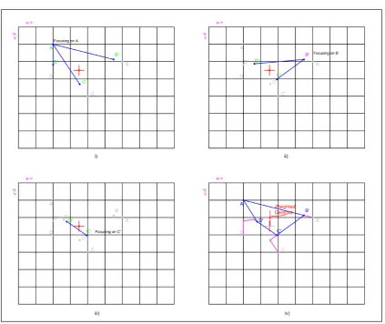
4.2 Profiling/Fingerprinting Localisation . . . 44
4.3 Centroid Algorithm . . . 46
4.4 Weighted Centroid Algorithm . . . 46
4.5 Collection Tree Routing Protocol (CTP) . . . 48
4.6 Chapter Summary . . . 50
Chapter 5 System Design and Implementation 51 5.1 Chapter Overview . . . 51
5.2 System Architecture . . . 51
5.3 System Hardware . . . 53
5.4 System Software . . . 54
5.4.1 User interface . . . 55
5.4.2 Profiling Function . . . 56
CONTENTS ix
5.4.4 Defining Safe/Unsafe areas function . . . 59
5.4.5 Graph Function . . . 61
5.4.6 Semi-Automated Accuracy Testing Function . . . 61
5.4.7 Setup Function . . . 62
5.5 Software Modules for Distributed Sensor Motes . . . 63
5.5.1 Target Node Function . . . 64
5.5.2 Static Nodes . . . 64
5.5.3 Root Node (Base Station) . . . 64
5.6 Chapter Summary . . . 67
Chapter 6 Evaluation And Testing 68 6.1 Chapter Overview . . . 68
6.2 Evaluation Design . . . 68
6.2.1 Evaluation Metrics . . . 68
6.2.2 Design of Testing Procedures . . . 69
6.2.3 Boundary Test Design . . . 73
6.3 Testing and Results . . . 74
6.3.1 Localisation Testing . . . 74
6.3.2 Comparison of Localisation Tests . . . 81
6.3.3 Sensor Orientation . . . 83
6.3.4 System Response Time . . . 87
CONTENTS x
6.4 Chapter Summary . . . 90
Chapter 7 Conclusions and Further Work 92 7.1 Research Objectives - Key Findings and Conclusions . . . 92
7.2 Closing Summary . . . 95
References 96 Appendix A Project Specifications 108 Appendix B Datasheets 110 Appendix C Code Listings 117 C.1 TelosB mote code . . . 117
C.1.1 AIMSAppC.nc . . . 117
C.1.2 AIMSC.nc . . . 118
C.1.3 AIMS.h . . . 123
C.1.4 AIMS BEACON.h . . . 123
C.2 Localisation Software Code . . . 124
C.2.1 Main Application aims.c . . . 124
C.2.2 WSN interface wsn if.c . . . 131
C.2.3 Database interface db if.c . . . 139
C.2.4 Centroid Algorithms vector.c . . . 159
CONTENTS xi
C.2.6 AIMS Makefile . . . 164
C.3 Matlab Data Analysis Code . . . 164
C.3.1 Baseline Testing Analysis Code . . . 164
C.3.2 Residential Testing Analysis Code . . . 166
Appendix D Setting Up Development Platform 168
List of Figures
1.1 Sketch of proposed system outline . . . 4
1.2 Market Projection of Wearable Devices (Wearable Technology Market -Global Scenario, Trends, Industry Analysis, Size, Share And Forecast 2012 - 2018 2013) . . . 6
2.1 Layout depicting a typical application for use by the proposed system . 14 2.2 Crossbow TelosB Wireless Sensor (MoteIV 2004) . . . 15
2.3 Transmission power reflected by the register values in the CC2420 . . . 16
2.4 Component A provides the interface for use by component B . . . 20
3.1 Trilateration technique showing signal propagation ‘circles’ (Boukerche, Oliveira, Nakamura & Loureiro 2007). . . 34
3.2 Triangulation technique showing angles from 2 beacons to the target node. (Abdelsalam & Olariu 2009b). . . 36
4.1 The Centroid of the 4 best database matches for localisation . . . 46
4.2 The Weighted Centroid of a 4 vertex polygon . . . 47
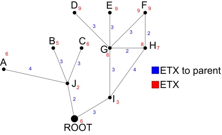
4.3 Example network showing the ETX gradient of nodes . . . 49
LIST OF FIGURES xiii
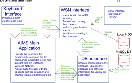
5.2 Basic Software Design Model . . . 55
5.3 Format of the the Beacon Frame . . . 56
5.4 Format of the the Data Frame . . . 56
5.5 Serial Frame transferred from Base Station . . . 57
5.6 State diagram for boundary control . . . 60
5.7 Sequence of events for receiving a Beacon Message . . . 65
5.8 Sequence of events for the root node receiving CTP messages . . . 66
6.1 Common residential home showing overlaid grid for visualisation . . . . 75
6.2 Testing the sterile area with LoS for all positions . . . 76
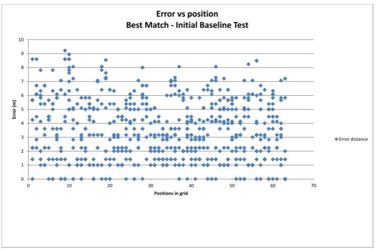
6.3 Scatter Plot for initial Baseline test. Indicates very random and spurious readings. . . 77
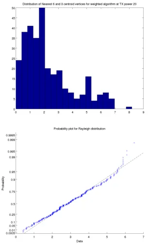
6.4 Baseline test distribution showing positive skewing and the probability plot against the Rayleigh Distribution. . . 79
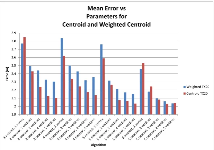
6.5 Mean Error vs Parameters for Weighted Centroid and Centroid Algorithms 81 6.6 Mean Error vs Algorithms for Home and Baseline tests . . . 82
6.7 Location distribution for different sensor orientations . . . 84
6.8 Location distribution for different sensor orientations . . . 85
6.9 Propagation Model of MicaZ mote with cc2420 Radio Chip (Azevedo & Santos 2007) . . . 86
6.10 RSSI Vs Angle of reference for TelosB mote at 3m. . . 87
6.11 Distribution Plot of System Response Time . . . 88
LIST OF FIGURES xiv
B.1 CC2420 Datasheet (Chi 2004) . . . 111
B.2 CC2420 Datasheet (Chi 2004) . . . 112
B.3 CC2420 Datasheet (Chi 2004) . . . 113
B.4 CC2420 Datasheet (Chi 2004) . . . 114
B.5 Crossbow TelosB Datasheet (Cro 2003) . . . 115
List of Tables
5.1 CSV file output from Test Function. Test Data2014 10 19 13 29 16.csv 62
6.1 Algorithm Test Table . . . 73
6.2 Baseline Test - Best Match Algorithm . . . 77
6.3 Comparison of algorithms for baseline tests . . . 80
6.4 Comparison of algorithms for residential rest . . . 80
E.1 Baseline Test Data . . . 172
E.2 Residential Test Data . . . 177
List of Algorithms
1 Profiling Algorithm . . . 45
Abbreviations
AoA Angle of Arrival
ADC Analogue to Digital Converter
API Application Programming Interface
APS Ad-hoc Positioning System
BAN Body Area Network
CAGR Compounded Annual Growth Rate
CTP Collection Tree Protocol
CSV Comma Separated Values
DOF Degrees of Freedom
DV Distance Vector
EMI Electro-Magnetic Interference
ETX Expected Transmissions
GPS Global Positioning System
HW Hardware
IDE Integrated Development Environment
IEEE Institute of Electrical and Electronic Engineers
IPTS Indoor Personnel Tracking System
LEMON Location Estimation by Mining Oversampled Neighbourhoods
LoS Line of Sight
LQI Link Quality Indication
LTS Long Term Support
MAC Media Access Control
MEMS Micro-Electro-Mechanical-Systems
ML Maximum Likelihood
MMSE Minimum Mean Square Error
NAT Network Address Translation
NLoS Non-Line of Sight
OEM Original Equipment Manufacturer
OS Operating System
PoA Phase of Arrival
PC Personal Computer
PDM Probability Density Map
PDR Pedestrian Dead Reckoning
PRR Packet Reception Rate
RF Radio Frequency
RFID Radio Frequency Identification
RSSI Received Signal Strength Indicator
SW Software
ToA Time of Arrival
TMP Time Management Plan
TDoA Time Difference of Arrival
TX Transmit
WAF Wall Attenuation Factor
Chapter 1
Introduction
Wireless Sensing Networks are fast-evolving into an era where the Internet Of Things is
the “Hot Topic” for research and information gathering systems. Extensive research has
already been undertaken into localisation and object tracking in indoor applications,
but there is little in the way of complete solutions for home health and safety. This
project aims to research current solutions and localisation approaches and aims to
produce an out of the box solution for in-home localisation for home health and safety.
The motivation for the project emerged with the startling statistics of the amount of
children below 5 dying in backyard swimming pools. The Royal Life Saving National
Drowning Report stated that 19 children under 5 drowned in swimming pools alone in
the 2012/13 financial year. In addition, 4 more children died from drowning in spas in
the same period of time (Lifesaving Society Australia 2013). This raises the question
as to whether the emerging WSN technology can be used to assist in reducing these
incidents.
For completeness, a Market Research was undertaken in the preliminary stages of the
project to discover the strengths and weaknesses of the WSN market . The
com-pounded annual growth rate of WSN’s in 2011 was at 42% (Shalini 2012), and market
confidence shows interest in this evolving technology. Market projections for wearable
devices which include WSN nodes also strengthen this confidence as shown in
Fig-ure 1.2. Torres-Solis, Falk & Chau (2010) state that there is “immense” opportunity
in implementing an indoor localisation scheme, particularly in the area of providing
1.1 Project Aims 2
It was found during an analysis of the literature that the area of using WSN’s for child
monitoring and health and safety has not been widely researched or applied in practice.
This opens an area whereby a possible new application for pervasive computing can be
applied.
1.1
Project Aims
This project aims to research, design and implement an out-of-the-box solution for
personnel localisation in homes or residential buildings. It is proposed that we deliver
a solution whereby the user requires minimal set-up time and technical knowledge in
order to successfully interact with the WSN in the home.
The basis for the selection of this topic is to propose anopen source andcost effective
solution to localisation for indoor/residential applications in the interest of increasing
the standards of living in and around the home, particularly in the application area of
home health and safety.
In addition to the swimming pool deaths previously stated, one child is injured to some
extent in the driveway every week by a motor vehicle (Eccleston 2014)1. With that comes the opportunity for using pervasive computing to help solve health and safety
issues or enhance the quality of life for people in and around their homes.
Examples of uses for such an application are as follows:
• Child Monitoring—Anyone who has children will know that a toddler loves to
explore, and this may mean that they can go out of sight in the blink of an eye.
If predetermined “limits” were set out, a parent could be reassured that the child
is within those limits if no alarm was to be raised2
• Patient Monitoring—Six out of ten patients who suffer from dementia or related
illnesses can wander even in familiar places (www.alz.org 2014). This could put
them in a situation whereby they could be injured or injure other people.
1
The extent of the injuries are reported to be from minor to fatal
2
The author in no means portrays that it is acceptable for the parent leave the child
unsuper-vised. There are many variables that must be considered before the proper implementation of such an
1.2 Objectives, Parameters and Constraints 3
Preliminary technology-based research was undertaken into the different wireless
tech-nologies — their strengths, weaknesses and opportunities. It was declared that the
sensors that comply to IEEE802.15.4 would be the most suited to the application
be-cause of the low power and low cost of the devices. Amongst the considerations were —
WIFI, Bluetooth and RFID. The main factors against the common infrastructure item,
WIFI, was the bandwidth usage and power usage. Bluetooth only has a sensing range
of 10m and is very high in power usage and cost (Chu, Wang, Liang, Ouyang, Cai &
Chen 2011). RFID has a sensing range of only 1-2m and the cost of an RFID reader is
relatively high (Liu, Darabi, Banerjee & Liu 2007). Furthermore, the university
sup-plied Crossbow Telosb motes are IEEE802.15.4 compliant, low power, low cost and can
be easily adapted/programmed using the TinyOS operating system which is designed
for such devices3. Tafa (n.d.), who wrote “Sensor Networks in Pervasive Health-care Computing”, states that “this operating system is very appropriate for most of the
WSN applications including those used in health-care”.
1.2
Objectives, Parameters and Constraints
The major objective of this project is to design and implement an effective indoor
localisation system whereby a wireless sensor is able to be effectively tracked within
a WSN. The term “localisation” in relation to WSN’s can be defined as finding the
location of a sensor’s physical position in a deployment area efficiently (Abdelsalam &
Olariu 2009b).
The localisation data is routed to a local computer/router where it is used to calculate
an estimated position of the target and perform higher level tasks based upon a set of
pre-defined rules.
An example of such rules could be that a certain area is not to be breached or an
audible alarm will sound in conjunction with a call to the guardian’s mobile phone.
Figure 1.1 shows an illustration of the basic proposed system.
A practical viewpoint was taken when defining the parameters of this project which
includes the fact that indoor localisation must tackle the expectation of obstacles in the
localisation area. Krishna & Doja (2011) state that building walls, reflecting surfaces,
1.2 Objectives, Parameters and Constraints 4
Figure 1.1: Sketch of proposed system outline
objects (transparent and opaque), and room shape are factors that must be considered
when localising indoors. Another factor that must be considered is the latency of
localisation. The system must be able to localise a moving object in real time. These
variables are evaluated during testing and are considered to be the most important
metrics as a real-life scenario is the aim of the project.
Certain assumptions and constraints were derived so that the project was able to be
completed and tested with the supplied resources and within the supplied time frame.
These constraints may be relaxed or removed as an opportunity for future work. These
parameters indicate the particular situational, environmental and technological basis
for which the design is to consider as the high-level inputs to the system:
2D localisation only — 3D localisation systems require more time spent on
applica-tion writing as well as the fact that the added dimension opens up more
oppor-tunity for localisation error.
Use of Telosb Crossbow motes — The author has limited prior knowledge into
1.3 Market Research 5
platform. Furthermore, as research progressed, more evidence concreted the use
of crossbow motes, namely their adherence to IEEE802.15.4 defining low power,
low cost devices.
Programmed in nesC with TinyOS — Preliminary research and tutorials into TinyOS
and nesC has formed the basis for using the Crossbow motes and TinyOS.
Open Source — For contribution to the research community, an open source software
system is to be adhered to.
Low Cost — Cost is to be kept at a minimum without compromising the functionality
of the system. The estimated budget for a complete system should be less than
$300.
Time Constraint —Research, design, test and implement in 37 weeks. The deadline
for this project to be complete and tested is 24th October 2014. This enables the
author time to proof-read and print the final documentation of the project which
has a due date of 30th October 2014.
1.3
Market Research
This section aims to describe the condition of the current Wireless Sensing Network
market. It’s not an exhaustive Market Research document, but rather an indication
to the reader as to the motivations behind this project4. The WSN market is obscure in the fact that there are two tiers in the way we see Wireless Sensors. These being
the “WSN solutions” and the “devices” themselves. This difference is outlined in the
sections 1.3.1 and 1.3.3 but in general, we can consider the tiers as markets for end-users
or developers/designers.
As this project is based on “indoor” WSN’s, the research in respect to end users is
focused on “smart homes” and WSN solutions for residential areas5.
The IEEE802.15.4 and ZigBee standard has a large market share in smart metering,
4A full market research would have taken too much time away from the design and implementation
of the project, although an idea of the shape of the market is important
5
At times the line between industrial solutions and in-home solutions is grey in their application,
1.3 Market Research 6
Figure 1.2: Market Projection of Wearable Devices (Wearable Technology Market - Global Scenario, Trends, Industry Analysis, Size, Share And Forecast 2012 - 20182013)
energy management and resource management (Hatler, Gurganious & Chi 2014). There
is also strength in the ZigBee market in regards to consumer confidence and preferences
with most people regarding ZigBee as “familiar” or “most familiar”. One negative
aspect of using a sensor in the 2.4GHz frequency band, (such as ZigBee) is that the
frequency band is “crowded” and suffers “limited range”. Renesas are contributing
to the development of an international sub-GHz standard, but it has not yet become
available (Mametani n.d.). We believe it would be too pre-emptive to adopt an
un-released standard for the proposal of a new solution.
Because of the interoperability of ZigBee sensors, it would prove favourable to continue
with market trends and momentum. The worldwide trend in revenue of WSN’s is
rising and expected to rise as outlined in this chapter. Also, the amount of companies
offering out-of-the-box solutions for WSN localisation is very small. We consider this an
opportunity for this project to enter the market place in a competitive and comfortable
state.
1.3.1 Market Definitions
Indoor localisation techniques using WSN’s can be purchased from specialised WSN
firms that create a total solution, although this market is not well described or
adver-tised. This was evident when researching specific companies offering solutions to home
owners. Total solutions for homes are directed more towards smart energy, security
1.3 Market Research 7
As for a developer who would potentially offer a solution such as the one proposed by
this project, the technical aspect of the WSN market is very large and well defined.
The market leaders on Wireless sensor technology are Renesas, Microsemi, Silicon
Lab-oratories, Linear Technology / Dust Networks, Texas Instruments / National Semi,
Lord, Semtech, Analog Devices, Millennial Net. Although companies such as Renesas
provide the lower level IC’s to intermediate firms who design and assemble the sensors.
1.3.2 Market Size
Globally, the market for wireless sensor devices was $532 million in 2010 and $790
million in 2011 with a CAGR (Compounded Annual Growth Rate) of 46%. (Shalini
2012). At the current standpoint in early 2014, 9 billion devices are connected to the
Internet (www.researchmoz.us 2014). With the growth rate increasing each year, we
can predict that the market is accepting the IoT as a part of everyday life and we can
consider it as sense of confidence for pursuing a project in this area.
1.3.3 Market Segmentation
As previously stated, the market is split into two main tiers. On one side, there is the
portion of the market who purchase the end product or the solution. For example, the
home owner will purchase a WSN energy saving package from a company who supplies,
installs and commissions the sensors. The other side of the market is based on the
developers and designers of WSN’s and the portion of the market who create OEM
systems for specific purposes.
For the purposes of this project, we need to consider both of these tiers as we will
be striving to develop a device that uses the “technical” aspects (such as sensors,
controllers, base-stations etc). We must also consider the current market as it stands.
For example if the market is saturated with solutions similar to the one proposed, then
1.3 Market Research 8
1.3.4 Market Trends
According to www.researchmoz.us (2014) the amount of devices connected to the
in-ternet is set to rise to 100 billion by 2020. Focusing in on our area of research, WSN
revenues from smaller buildings will increase 60% faster than larger buildings over the
next five years. In 2017, global WSN revenues from buildings under 50,000 square feet
will reach $1.3 billion up from $127 million in 2012” (Hatler, Gurganious & Chi 2013).
Although the definition of a small building is relatively large, one can get an indication
of the market direction and momentum of WSN’s in smaller buildings.
“there will be 50 million smart homes and buildings enabled by wireless sensor network
(WSN) technology”, according to global technology research firm ON World.
The do-it-yourself (DIY) model is preferred or most preferred by half of the respondents
compared with 41% that would prefer to purchase from a cable/broadband service
provider. ZigBees brand recognition continues to grow as 45% more consumers ranked
it as Familiar or Most Familiar in 2013 compared with ON Worlds previous survey in
2012.
Between 2012 and 2018, ZigBee and IEEE802.15.4 based systems will make up 43% of
the wireless chip-sets used for smart metering, home and building energy management,
distributed energy resources as well as lighting controls.
1.3.5 Market Forecasts
As previously stated, the future of the IEEE802.15.4 market remains strong and
contin-ues to grow. As the trend has not started to plateau, one can expect strong continuous
growth. Hatler et al. (2014) describes the future in WSN devices with the following
statement:
“In fact, revenues from ZigBee/15.4 devices and associated equipment will
reach $50 billion (up from previous years) within the next few years” (Hatler
1.3 Market Research 9
1.3.6 Market Research Summary
The state of the WSN market can be summarised as a market that achieves strong
growth and a successful short-medium term future. In addition to the state of the
market, it can be concluded that from the information gained from a product search
and comparison (available on request), the devices that are currently available in the
market for retail sale are costly and somewhat sparsely defined in terms of power,
localisibility and adaptability. In regards to development products such as the Ember
by Silicon Labs, the price for a SW license and development kit is expensive and ongoing
1.4 Overview of the Dissertation 10
1.4
Overview of the Dissertation
The rest of this dissertation is organised as follows:
Chapter 2 is an overview of the background information that encompasses all facets
of this project. Included are the current systems in place, an insight into the
tech-nology and an introduction to to the communications protocol and TinyOS/NesC
programming structure.
Chapter 3 is a comprehensive review of the literature surrounding indoor localisation
techniques and the application to health and safety applications. This review
was used as the foundation for further research into the child health and safety
monitoring system.
Chapter 4 defines the the theoretical concepts developed in this project in order to
adhere to the project objectives. Algorithms are defined in this section in addition
to further information into the Collection Tree Routing Protocol.
Chapter 5 introduces the AIMS system. This acronym stands for Adaptable Infant
Monitoring System. The section details the design steps including hardware,
software and system design and gives finer details of the functionality of the
system.
Chapter 6 defines the evaluation and testing procedures and displays the results of
the tests including further testing of re-design stages.
Chapter 7 concludes the project with an evaluation of the objectives and how they
were met. Further work and research opportunities are also discussed.
1.5
Chapter Summary
The main focus points delivered in Chapter 1 are centred around using a Wireless
Sensor Network to assist in reducing the number of childrens lives lost from drowning
in swimming pools. The aims of the project are to research and deliver a versatile and
user friendly WSN system which can detect the position of a child in a sensor network
1.5 Chapter Summary 11
A market research was undertaken which showed that the state of the WSN market is
strong and consumer confidence in the technology is high. Actual WSN devices were
researched for price and usability, but it was concluded that the university supplied
TelosB wireless sensor be utilised because of the availability and adherence to the
low-cost, low power IEEE802.15.4 network protocol.
Additional constraints were defined including a maximum cost of $300 for the total
system package deliverable to the home. The system is to be programmed and made
open source using TinyOS and NesC. Localisation will be in 2 dimensions, and the time
Chapter 2
Technology and Tools
2.1
Chapter Overview
In order to have an objective view on the scope of the proposed system, the existing
technology in child safety monitoring was researched. This research included papers,
products and patents and a critical analysis of the solutions was made. Furthermore,
the application areas and scenarios for the proposal are defined in conjuction with
introductions to the tools required to meet the objectives. These tools give the reader
the essential background understanding of the building blocks of the proposed system.
2.2
Current Technology in Child Safety Monitoring
Pool monitoring devices have been designed and patented since the 1970’s all over the
world. Amongst those are wave monitoring devices (Codina 1972) & (Millen 1983);
wearable submersion devices that wirelessly transmit when the device is submerged
(Quinones 1996) & (Flood 1998); Swimmer motion and behaviour tracking devices
such as the system designed by Miller, Halwachs & Farstad (1999) where they use
electromagnetic pulses to track and transmit the swimmers behaviour and position;
video monitoring devices that track swimmer movements and locations (Lu & Tan 2004)
2.3 Application Areas 13
Wu, Cai, Huo, Wu & Zhou (2013) designed a wearable drowning monitor whereby the
micro-controller system is worn by the child and when the child is detected to be at a
certain depth and movement is in a window of set parameters , then an alarm is raised.
This design is aimed for use at crowded swimming pools in china where supervision is
‘difficult’. It is acknowledged that in this circumstance, the design has merit and is a
viable solution for children who can already swim but may have sustained an injury
causing unconsciousness in the water.
Taking into account the merits of the aforementioned designs, it is clear that these
systems are only valid for discrete locations or swimming pools alone. The research
direction and proposed solution outlined in this document is highly versatile whereby
the user can define the areas that they deem as unsafe and it doesn’t necessarily need
to be a swimming pool. The unsafe area may be a bathroom, garage, or driveway
etc. This versatility along with the low cost will be more saleable in the growing WSN
marketplace.
Furthermore, the use of a system where the boundaries are defined by the user means
that the alarm can be raised BEFORE the child enters the water. This saves precious
time in an emergency situation.
2.3
Application Areas
This project is aimed primarily at the domestic market whereby the system can be
used in a normal home. A person who is deemed to be at risk in some way would have
the target sensor attached to them. The areas in which the person may move around
in are recorded into the systems computer prior to attachment of the target sensor.
Unsafe areas are defined by the user to the software in order to set out boundaries
for alarming purposes. Once the person breached the boundaries, the alarm would
be raised to the user. The image in Figure 2.1 shows a typical application scenario
whereby the person who is being tracked is allowed inside the house, but not outside.
There are 2 physical exits whereby the wearer of the sensor would be able to enter the
forbidden zone marked in yellow.
The application domain does not restrict itself to a particular scene such as a swimming
2.4 Introduction to Wireless Sensor Networks 14
patients or dementia patients who may get lost or enter an unsafe area where they may
injure themselves or others. In addition, the system may be used to create an unsafe
area around water tanks which is also a known risk for drowning amongst children
(anon 2014).
Figure 2.1: Layout depicting a typical application for use by the proposed system
2.4
Introduction to Wireless Sensor Networks
WSN’s are defined as a network of small embedded systems with wireless
connectiv-ity via radio link that can perform tasks, gather information or route information to
other sensors. Network types can vary in their formation, topology, communication
protocol, routing protocol and communication range. Applications of wireless sensing
networks range from monitoring environmental variables, activating remote devices,
monitoring health of hospital patients (Purvis 2014), tracking assets and the location
of objects/people, and even for security surveillance. The applications for wireless
sens-ing networks is startsens-ing to evolve more as the price of purchassens-ing and implementsens-ing a
WSN falls to affordable levels.
Pervasive computing has fast become an accepted part of life over the last decade. More
and more computers and computer controlled devices are used to perform tasks that
we take for granted. Examples are automated toll gates on toll-roads and automated
2.5 Crossbow TelosB Wireless Sensors 15
consumer market with Smart Metering devices and smart home automation controllers.
2.5
Crossbow TelosB Wireless Sensors
Telosb wireless sensors from Crossbow Inc have been specifically designed to enable
cutting edge experimentation for the research community. The incorporation of the
low power MSP430 MCU and CC2420 radio chip enables researchers to use the latest
technology which adheres to the IEEE802.15.4 communications standard. In addition
to this, the mote has on board temperature, humidity and light sensors as well as a
USB connection for ease of programming and interface (Cro 2003). Thedatasheetfor
the TPR2420CA can be found in Appendix B.5.
Figure 2.2: Crossbow TelosB Wireless Sensor (MoteIV 2004)
According to Gao, Zhou & Su (2011), the three major goals of the TelosB for
soft-2.5 Crossbow TelosB Wireless Sensors 16
ware/hardware robustness. The CC2420 radio chip allows for various transmit power
settings (-25dBm ->0dBm) as shown in Figure 2.3, which allows the developer to tune
the transmission range for lower battery consumption (See B.4 for output current
con-sumption). In addition, the utilisation of the MSP430’s low power operation, sleep and
active modes allows further reduction in power usage by the mote.
Figure 2.3: Transmission power reflected by the register values in the CC2420
2.5.1 Hardware components
The Crossbow telosb mote has been designed with additional functionality built into
the hardware of the device. Included in this functionality is a temperature sensor,
humidity sensor, total-solar radiation sensor and a photo synthetically-active radiation
sensor (MoteIV 2004). The USB interface allows ease of connection and programming
of the device in conjunction with the ability of using the USB for a power source. More
importantly, the USB can act as the primary channel from the WSN to the outside
world.
2.5.2 IEEE802.15.4 Communications
The TelosB mote, coupled with the CC2420 radio chip adheres to the 802.15.4
2.5 Crossbow TelosB Wireless Sensors 17
915MHz and 2.45GHz1. This standard defines the PHY and MAC layers and its main objectives are: ease of installation, reliable data transfer, low cost and extended battery
life — whilst maintaining a simple, yet flexible protocol (IEEE 2011). These objectives
are coupled with the intent for incorporating little or no further infrastructure.
The Physical Layer PHY
The physical layer provides the data transmission from the device. It is the layer
that interacts directly with the RF transceiver providing services such as channel
se-lection, energy management and signal management functions. 2.45GHz using the
IEEE802.15.4 standard communicates through using Digital Sequence Spread
Spec-trum (DSSS). The CC2420 radio module incorporated in the TelosB handles the PHY
later functionality in addition to many of the MAC functions described in 2.5.2.
The Media Access Control Layer MAC
TinyOS in conjunction with the CC2420 driver and CC2420 chip handle the MAC
functionality (TinyOS 2013). The MAC layer enables the transmission of MAC frames
and provides addressing and channel access mechanisms. Error protection is achieved by
generating MAC frame checking sequences. The MAC layer also incorporates a control
mechanism so that multiple communication mechanisms cannot access the radio chip
simultaneously. This multiplexing allows the seamless operation of different network
protocols operating over the same physical communication medium.
Access to the radio chip uses the CSMA/CA (Carrier Sense, Multiple Access with
Collision Avoidance) control algorithm. CSMA/CA basically means that the device
will listen on the network until there is no transmission heard. It keeps waiting until the
channel is free and then sends a frame. It waits for an acknowledge from the receiving
device before deeming success or failure. If the frame collides, the MAC functionality
goes into a transmission delay called Binary Exponential Back-off whereby it waits a
predetermined amount of time before starting the CSMA sequence again (IEEE 2011,
pp21-23).
1The TelosB wireless sensors used for this project use the 2.45GHz band, and therefore 2.45GHz is
2.5 Crossbow TelosB Wireless Sensors 18
TinyOS provides this MAC functionality as an abstraction through the Active Message
interface which is discussed in Section 2.5.3. Active Messages are directly accessible
through the application layer.
2.5.3 Wireless Sensor Software Development (TinyOS and nesC)
Introduction
TinyOS is an operating system designed for low power embedded systems such as
wire-less sensors. It consists of a scheduler and drivers for a suite of different micro-controllers
and hardware components. TinyOS is written using a programming language called
‘nesC’ which stands for ‘Network Embedded Systems C’ which is a component based
and event driven (TinyOS 2013). The scheduler in TinyOS is very lightweight and
robust. It schedules tasks in a round-robin technique whereby there is no concurrency
and therefore it is favourable that short un-nested tasks are used.
The program structure of nesC varies significantly to a normal C program but the
nor-mal syntax of the code remains very similar. The nesC structure uses components and
interfaces which are ‘wired’ together to form an application. According to Levis (2006),
wiring is the most challenging concept about nesC for people new to the language. The
following sections give the reader background information to the programming construct
and calling mechanism of NesC. These sections aim to give a basis to understanding
this wiring technique and how TinyOS can be used as a flexible and robust operating
system for wireless devices.
Components and Interfaces
In nesC, Components are similar to objects in the fact that they encapsulate the
func-tionality of a certain program element. A component in nesC has a “specification”
and an “implementation”. The specification defines the functions that the component
provides and uses. These functions are usually grouped together in “interfaces” defined
below. The implementation is the actual code that the component provides. For
ex-ample if a component provides a function called open(), then the implementation for
2.5 Crossbow TelosB Wireless Sensors 19
There are 2 types of Components: A Component Module provides the implementation
of the interfaces that a component defines in it’s specification. A Component
Configu-ration is a way of linking different components together through their interfaces. This
is discussed later.
Listing 2.1 shows an example of how component module is structured. The specification
is defined in the “module” section where the interfaces that it uses and provides are
defined. These used interfaces must be provided by a higher level component in order
for the functionality of this component to be valid. The implementation section shows
the actual callback for the Boot interface event called booted(). So when the booted
event is raised, this code is called. In turn, the booted() function in this example then
uses the SplitControl interface to start another lower level component. Note that the
name of the interface can be changed by using the ‘as’ directive.
Listing 2.1: necC ‘Component Module’ 1 //
,→ −−−−−−−−−−−−−−−−−−−−−−−−−−−−−−−−−−−−−−−−−−−−−−−−−−−−−−−−−−−−−−−−−−−−−−−−−−
,→
2 module ComponentC ( ){ 3 u s e s {
4 i n t e r f a c e Boot ;
5 i n t e r f a c e S p l i t C o n t r o l a s R a d i o C o n t r o l ;
6 }
7 }
8 i m p l e m e n t a t i o n {
9 // Must d e f i n e i m p l e m e n t a t i o n o f t h e b o o t e d e v e n t p r o v i d e d from
,→ t h e
10 // b o o t i n t e r f a c e
11 e v e n t v o i d Boot . b o o t e d ( ) { 12
13 // C a l l t h e s t a r t f u n c t i o n p r o v i d e d by t h e S p l i t C o n t r o l 14 // i n t e r f a c e .
15 i f (c a l l R a d i o C o n t r o l . s t a r t ( ) != SUCCESS) 16 f a t a l p r o b l e m ( ) ;
17 }
18
19 // Must d e f i n e i m p l e m e n t a t i o n o f s t a r t D o n e e v e n t 20 e v e n t v o i d R a d i o C o n t r o l . s t a r t D o n e ( e r r o r t e r r o r ) { 21 i f ( e r r o r != SUCCESS)
22 f a t a l p r o b l e m ( ) ;
23 // a p p l i c a t i o n c o d e can go h e r e . .
24 // . . .
25 }
26 } 27 //
,→ −−−−−−−−−−−−−−−−−−−−−−−−−−−−−−−−−−−−−−−−−−−−−−−−−−−−−−−−−−−−−−−−−−−−−−−−−−
,→
Interfaces - Collections of related functions that can be used by or provided to
compo-nents. An example of a commonly used interface is the standard control interface:
The standard control interface defines 2 functions called start() and stop(). A
compo-nent that “provides” this interface must therefore define the implementations for the
2.5 Crossbow TelosB Wireless Sensors 20
which are related to different components in the same application (Levis 2006, pp.
22-24). A set of “used” interfaces outlines to the user the interfaces it needs to perform its
job. The functions defined in the interface have two directives called a “command” or
an “event”. A command is to be defined by the component that provides the interface
and the “event” is to be defined by the component that uses that interface. An example
of the SplitControl interface is shown in Listing 2.2.
Listing 2.2: nesC ‘interface’ 1 //
,→ −−−−−−−−−−−−−−−−−−−−−−−−−−−−−−−−−−−−−−−−−−−−−−−−−−−−−−−−−−−−−−−−−−−−−−−−−−
,→
2 i n t e r f a c e S p l i t C o n t r o l {
3 command e r r o r t s t a r t ( ) ; // i m p l e m e n t a t i o n d e f i n e d by t h e
,→ component
4 // t h a t t h i s i n t e r f a c e i s w i r e d t o . 5 e v e n t s t a r t d o n e ( e r r o r t ) ; // i m p l e m e n t a t i o n d e f i n e d by c a l l i n g
,→ component
6 command e r r o r t s t o p ( ) ; 7 }
8 //
,→ −−−−−−−−−−−−−−−−−−−−−−−−−−−−−−−−−−−−−−−−−−−−−−−−−−−−−−−−−−−−−−−−−−−−−−−−−−
,→
The block diagram in Figure 2.4 gives a visual representation of how components and
interfaces interact. Although it is noted by Levis (2006, pp. 34) that it is “dangerous
to signal events from commands”, the intention of the drawing is to give the reader an
intuition of the calling structure of the code without introducing complexities.
Figure 2.4: Component A provides the interface for use by component B
The second type of Component is called a ‘configuration’. A configuration is used to
“wire” components together by connecting their interfaces. Every nesC application
has at least one configuration that wires the components together (Gao et al. 2011).
Configurations not only connect interfaces together, but they also can “export”
inter-faces (Levis 2006, pp. 54). Exporting means that an interface my not be required by
a certain component, but can be used by a higher level component. Consider the case
where the lower level application code receives the Received Signal Strength from the
CC2420 radio chip. The higher level code may not require this information, but and
2.5 Crossbow TelosB Wireless Sensors 21
for use by the application developer.
Component Configurations also have a specification and implementation section. The
implementation section is used to define the actual wiring and components used. The
specification is used to define interfaces that are provided or used for calling and caller
components. The specification in the top level application component may be empty.
An example application including a configuration is shown in Listing 2.3 which gives
the reader a better intuition as to the wiring and structure. ComponentC from Listing
2.5 Crossbow TelosB Wireless Sensors 22
Listing 2.3: nesC ‘Configuration’ and one of the Module files
1 //−−−−−−−−−−−−−−−−−−−−−−−−−−−−−−−−−−−−−−−−−−−−−−−−−−−−−−−−−−−−−−−− 2 //MyApp . nc
3 //−−−−−−−−−−−−−−−−−−−−−−−−−−−−−−−−−−−−−−−−−−−−−−−−−−−−−−−−−−−−−−−− 4 // C o n f i g u r a t i o n
5 c o n f i g u r a t i o n MyAppC { } 6 i m p l e m e n t a t i o n {
7 components MainC , ComponentC , RadioC , SubC ; 8
9 ComponentC . Boot −> MainC ; // MainC p r o v i d e s t h e Boot i n t e r f a c e 10 ComponentC . S p l i t C o n t r o l −> RadioC ; // RadioC p r o v i d e s
,→ s p l i t c o n t r o l 11
12 RadioC . s u b C o n t r o l −> SubC ; //SubC a l s o p r o v i d e s a s p l i t c o n t r o l 13 }
14 //−−−−−−−−−−−−−−−−−−−−−−−−−−−−−−−−−−−−−−−−−−−−−−−−−−−−−−−−−−−−−−−− 15 // RadioC . nc
16 //−−−−−−−−−−−−−−−−−−−−−−−−−−−−−−−−−−−−−−−−−−−−−−−−−−−−−−−−−−−−−−−− 17 module RadioC {
18 p r o v i d e s i n t e r f a c e S p l i t C o n t r o l ; 19 // . . .
20 u s e s i n t e r f a c e S p l i t C o n t r o l a s s u b C o n t r o l ; 21 }
22
23 i m p l e m e n t a t i o n { 24
25 command e r r o r t S p l i t C o n t r o l . s t a r t ( ){ 26 // s t a r t d e v i c e h e r e
27 r e t u r n SUCCESS ;
28 }
29 // . . .
30 command e r r o r t S p l i t C o n t r o l . s t o p ( ){ 31 // s t a r t d e v i c e h e r e
32 r e t u r n SUCCESS ;
33 }
34 // . . . 35
36 t a s k v o i d f o o ( ) {
37 // . . .
38 c a l l s u b C o n t r o l . s t a r t ( ) ; // c a l l s t h e s p l i t c o n t r o l i n t e r f a c e
,→ o f
39 // t h e SubC component
40
41 s i g n a l S p l i t C o n t r o l . s t a r t D o n e ( ) ; // s i g n a l s e v e n t t o b e run
,→ by
42 // t h e c o d e i n ComponentC
43 // . . .
44 }
45
46 t a s k v o i d ba r ( ) {
47 // . . .
48 s i g n a l S p l i t C o n t r o l . stopDone ( ) ;
49 }
50
51 e v e n t s u b C o n t r o l . S t a r t D o n e ( ) { 52 // s u b c o n t r o l h a s s t a r t e d 53 r e t u r n SUCCESS ;
54 }
55 }
Note that the specification for this configuration is empty (Line 5). This is the top
level file and therefore the component need not provide or use any external interfaces.
As mentioned, the implementation defines the components that are used before wiring
2.5 Crossbow TelosB Wireless Sensors 23
user to the provider. In the case of exporting an interface as previously mentioned, the
’=’ sign is used to signal that the ‘user’ doesn’t actually use the interface but provides
it to the next layer of abstraction. The wiring arrows can be reversed as long as the
arrow points from the user to the provider.
An example calling structure would follow a simple routine such as:
1. ComponentC gets signalled by Boot.Booted() when the sensor boots up.
2. (Listing 2.1 line 15) ComponentC calls SplitControl.start() which, through the
wiring, is wired to RadioC. Therefore RadioC.SplitControl.Start() (2.3 line 25) is
invoked.
3. Hypothetically, RadioC does some stuff, and waits for a return event before
post-ing the task foo() to the scheduler. When the scheduler runs foo() it calls
sub-Control.Start() (2.3 line 38). As we can see by the configuration wiring (2.3 line
12), ‘SubC’ provides that interface, so we know that SubC will signal an event
called subControl.StartDone() (2.3 line 51) when it has started.
4. After the return from subControl.Start() in the task foo() (2.3 line 38), the event
SplitControl.startDone() is signalled (2.3 line 41)and therefore invokes the
func-tion which is coded in ComponentC (2.1 line 20) called
event ComponentC.RadioControl.startDone().
As can be seen from following the simple calling structure above, the wiring and calling
sequence can be quite hard to follow. This requires the application developer to gain
experience in writing and learning the coding techniques in tinyOS and nesC before
embarking on an application.
The TinyOS wiki from Stanford university 2 has a number of tutorials and code ex-amples to help an application developer find their feet with nesC programming. It is
recommended that a minimum of graduate level programming or experienced enthusiast
is required to grasp the concepts of nesC development and programming (Levis 2006).
2
2.5 Crossbow TelosB Wireless Sensors 24
Radio Communication
This subsection will give a brief outline on how messages are sent using the simple
TinyOS message type called an Active Message. This is the lowest networking layer
and is typically implemented over the sensor’s radio. Active messages are single hop
without a routing layer above performing some sort of routing protocol. The messages
are given a type which is an 8 bit integer denoting the type of message in the packet
(Gao et al. 2011).
The first thing that needs to be done to create a TinyOS application that sends a
message via radio is to find which components are required to perform the task. The
component called ‘ActiveMessageC’ provides the following interfaces:
c o n f i g u r a t i o n ActiveMessageC {
p r o v i d e s {
i n t e r f a c e S p l i t C o n t r o l ;
i n t e r f a c e AMSend [ a m i d t i d ] ; i n t e r f a c e R e c e i v e [ a m i d t i d ] ;
i n t e r f a c e R e c e i v e a s Snoop [ a m i d t i d ] ; i n t e r f a c e Packet ;
i n t e r f a c e AMPacket ;
i n t e r f a c e PacketAcknowledgements ;
i n t e r f a c e PacketTimeStamp<T32khz , u i n t 3 2 t> a s
,→ PacketTimeStamp32khz ;
i n t e r f a c e PacketTimeStamp<T M i l l i , u i n t 3 2 t> a s
,→ P a c k e t T i m e S t a m p M i l l i ; i n t e r f a c e L ow Po w er Li s te ni ng ;
} }
Therefore one would guess that we we can write an application that uses these
in-terfaces to send a packet via the radio. Unfortunately, this is not recommended.
Following the tutorials on the TinyOS-wiki and spending some time trying to grasp the
concept, one will find that we need to use the virtualised interfaces called AMSender
and AMReceiver in conjunction with ActiveMessageC to send and receive packets. The
reason for this is because AMSender provides a virtualized abstraction disallowing 2
components sharing the radio to interfere with each other. ActiveMessageC is only
used for the SplitControl interface, i.e. turning on and off the radio.
g e n e r i c c o n f i g u r a t i o n AMSenderC ( a m i d t AMId) {
p r o v i d e s {
i n t e r f a c e AMSend ; i n t e r f a c e Packet ; i n t e r f a c e AMPacket ;
i n t e r f a c e PacketAcknowledgements a s Acks ;
} }
The AMSenderC component requires a parameter to be passed in. This is the
2.5 Crossbow TelosB Wireless Sensors 25
AMSenderC code and replaces all uses of the parameter with the value passed in. In
other words, when we create a ‘new AMSenderC(10)’ we create a new version of the
AMSender module with active message type set to 10. All messages sent through this
component will be sent with its type field set to 10.
From the above listing, we can see that the AMSenderC configuration provides us with
Packet, AMPacket and AMSend. Now we can use these interfaces to send a message.
The following code produces a simple calling sequence starting from the booted() event
and ending up using a periodic timer to send messages over the radio with active
message type set to 0x06.
Listing 2.4: Configuration for sending an AM via radio 1 //
,→ −−−−−−−−−−−−−−−−−−−−−−−−−−−−−−−−−−−−−−−−−−−−−−−−−−−−−−−−−−−−−−−−−−−−−−−−−
,→
2 //MyApp . nc 3 //
,→ −−−−−−−−−−−−−−−−−−−−−−−−−−−−−−−−−−−−−−−−−−−−−−−−−−−−−−−−−−−−−−−−−−−−−−−−−
,→
4 c o n f i g u r a t i o n MyApp{ } 5 i m p l e m e n t a t i o n {
6 components MainC ;
7 components ActiveMessageC ; 8 components new AMSenderC ( 0 x06 ) ;
9 components new T i m e r M i l l i C ( ) a s Timer ; 10
11 ComponentC . Packet −> AMSenderC ; 12 ComponentC . AMPacket −> AMSenderC ; 13 ComponentC . AMSend −> AMSenderC ;
14 ComponentC . S p l i t C o n t r o l −> ActiveMessageC ; 15 ComponentC . Timer −> Timer ;
16 } 17 //
,→ −−−−−−−−−−−−−−−−−−−−−−−−−−−−−−−−−−−−−−−−−−−−−−−−−−−−−−−−−−−−−−−−−−−−−−−−−
,→
Listing 2.5 requires a few explanations. Firstly note that the payload data has to be
requested from the ‘Packet’ module. This tells that component to return a pointer to
the payload area of the specified size. The payload is wrapped in layers as traditional
messages are when being transmitted. Also note that the data structure in message.h
uses ‘nx struct’. This is called a ‘platform independent’ type and is required because of
the differences in ‘endianness’ by different hardwares. For example when compiling for
a MSP430, if this struct werent defined, the CC2420 would deem the data incompatible
(Levis 2006, pp. 137-9).
Listing 2.5: Module for sending an AM via radio 1 //
,→ −−−−−−−−−−−−−−−−−−−−−−−−−−−−−−−−−−−−−−−−−−−−−−−−−−−−−−−−−−−−−−−−−−−−−−−−−
,→
2 //ComponentC . nc 3 //
,→ −−−−−−−−−−−−−−−−−−−−−−−−−−−−−−−−−−−−−−−−−−−−−−−−−−−−−−−−−−−−−−−−−−−−−−−−−
,→
2.5 Crossbow TelosB Wireless Sensors 26
6 u s e s i n t e r f a c e S p l i t C o n t r o l ; 7 u s e s i n t e r f a c e Boot ;
8 u s e s i n t e r f a c e AMPacket ; 9 u s e s i n t e r f a c e Packet ; 10 u s e s i n t e r f a c e AMSender ; 11 u s e s i n t e r f a c e Timer<T M i l l i>; 12 }
13 i m p l e m e n t a t i o n{ 14
15 b o o l busy = FALSE ; 16
17 e v e n t v o i d Boot . b o o t e d ( ) {
18 c a l l S p l i t C o n t r o l . s t a r t ( ) ; // s t a r t t h e r a d i o 19 // go t o s l e e p andd w a i t f o r t h e r a d i o t o s t a r t .
20 }
21
22 e v e n t v o i d S p l i t C o n t r o l . s t a r t D o n e ( e r r o r t e r r o r ) { 23 i f ( ! e r r o r )
24 c a l l BTimer0 . s t a r t P e r i o d i c ( TIMER PERIOD MILLI ) ;
25 e l s e
26 f a t a l p r o b l e m ( ) ;
27 // go t o s l e e p and w a i t f o r t i m e r t o f i r e
28 }
29 30
31 e v e n t v o i d Timer . f i r e d ( ) { 32
33 i f ( ! busy ) {
34 // g e t p o i n t e r t o t h e p a y l o a d
35 Msg∗ msg = ( Msg∗) (c a l l Packet . g e t P a y l o a d (&pkt , s i z e o f( Msg ) ) )
,→ ;
36 // s e t t h e p a y l o a d 37 msg−>d a t a 1 = 0x5A5A ; 38 msg−>d a t a 2 = 0xA5A5 ; 39
40 // Send t h e p a c k e t
41 i f (c a l l Send . s e n d (AM BROADCAST ADDR,
42 &pkt , s i z e o f( Msg ) ) == SUCCESS) {
43 busy = TRUE;
44 }
45 // go t o s l e e p and w a i t f o r sendDone ( )
46 }
47
48 e v e n t v o i d Send . sendDone ( m e s s a g e t∗ msg , e r r o r t e r r o r ) { 49 i f (& pkt == msg ) {
50 busy = FALSE ;
51 // message h a s b e e n s e n t !
52 }
53 }
54
55 //−−−−−−−−−−−−−−−−−−−−−−−−−−−−−−−−−−−−−−−−−−−−−−−−−−−−−−−−−−−−−−−−−− 56 // message . h
57 //−−−−−−−−−−−−−−−−−−−−−−−−−−−−−−−−−−−−−−−−−−−−−−−−−−−−−−−−−−−−−−−−−− 58 t y p e d e f n x s t r u c t Msg {
59 n x u i n t 1 6 t d a t a 1 ; 60 n x u i n t 1 6 t d a t a 2 ; 61 } Msg ;
Take note that when sendDone() is raised, the parameter passed is a pointer to the
message sent. This is to ensure that the message type that was sent is the actual message
that triggered this event. In the case of more components using the radio chip, it is
2.6 Interfacing a C application using the MySQL API 27
Conclusion
TinyOS and nesC provides structured and robust platform in which to develop
appli-cations for the WSN domain. It has been shown that in order to create an application
using TinyOS and nesC there is a fair level of understanding that is required. Once the
developer has learn the concepts of the language and calling structure, the platform
becomes very powerful and flexible. This section only provided a small introduction to
a very large topic. It was intended that the reader understand how event based is
im-plemented and how that can reduce the need for program loops which waste processor
time and in turn battery power.
2.6
Interfacing a C application using the MySQL API
Using the ‘MySQL C API’ requires some background knowledge in the way connections
are made to the databases and how data is returned. Creating queries is very similar
to using the printf() function with the SQL query as the parameter. The following
paragraphs will give a simple background on how a C program can use the MySQL
API for simple tasks.
Firstly the MySQL development library must be downloaded, in addition with having
the database software installed. The dev library is called “libmysqlclient-dev”. After
installation of the libraries, the API is accessed through the header file “mysql.h”. Using
the GCC compiler, the application files can be compiled and linked using “$(mysql config
–libs)”. This will include the library and it’s location.
To make a connection to a MySQL through a C function, the code requires the root
username and password. This gives the user the privileges to create and drop databases,
tables etc. There is an exhaustive amount of information about security and access
rights, but they will be discussed no further here. To connect to the database, the
following lines must be used:
MYSQL ∗conn = m y s q l i n i t (NULL) ;
i f ( ! m y s q l r e a l c o n n e c t ( conn , s e r v e r , u s e r , password , d a t a b a s e , 0 , ,→ NULL, 0 ) )
{
f p r i n t f ( s t d e r r , ”%s\r\n ” , m y s q l e r r o r ( conn ) ) ; m y s q l c l o s e ( conn ) ;
2.6 Interfacing a C application using the MySQL API 28
}
The parameters to the the mysql real connect() function, server, user, password and
database are strings holding the relevant information. If the function returns NULL
we have a problem connecting. The error from MySQL will be printed to stderr for
debugging purposes. Once the connection has been made, the user can continue
ma-nipulating the database. The connection pointer is then used in the database access
functions throughout that function call.
Queries are very simple, although the return from a query must be handled correctly
to reach the required information. A simple query to select all information from a table
is shown below 3.
Listing 2.6: MySQL API access to retrieve table contents 1 MYSQL RES ∗r e s u l t ;
2 MYSQL ROW row ; 3 i n t n u m f i e l d s = 0 ; 4 i n t i i = 0 ;
5
6 MYSQL ∗conn = m y s q l i n i t (NULL) ; 7
8 i f ( ! m y s q l r e a l c o n n e c t ( conn , s e r v e r , u s e r , password , d a t a b a s e , 0 ,
,→ NULL, 0 ) )
9 {
10 f p r i n t f ( s t d e r r , ”%s\r\n”, m y s q l e r r o r ( conn ) ) ; 11 m y s q l c l o s e ( conn ) ;
12 r e t u r n 1 ;
13 }
14 i f ( m y s q l q u e r y ( conn , ”SELECT ∗ from Main ; ”) ) 15 {
16 f p r i n t f ( s t d e r r , ”%s\r\n”, m y s q l e r r o r ( conn ) ) ; 17 m y s q l c l o s e ( conn ) ;
18 r e t u r n 1 ; // o r e x i t ( 1 ) i f you a r e n o t h a n d l i n g e r r o r e l s e w h e r e . 19 }
20 r e s u l t = m y s q l u s e r e s u l t ( conn ) ;
21 n u m f i e l d s = m y s q l n u m f i e l d s ( r e s u l t ) ; 22
23 row = m y s q l f e t c h r o w ( r e s u l t ) ; 24
25 w h i l e ( row != NULL} 26 {
27 // l o o p t h r o u g h e a c h f i e l d i n t h a t row 28 f o r ( i i = 1 ; i i < n u m f i e l d s ; i i ++) 29 {
30 // need t o u s e o n l y rows t h a t h a v e non−n u l l v a l u e s 31 i f ( row [ i i ] != NULL)
32 {
33 p r i n t f (” %2.4 f , ”, a t o f ( row [ i i ] ) ) ;
34 }
35 e l s e
36 {
37 p r i n t f (”NULL\r\n”) ; 38
39 }
40 p r i n t f (”\n\r ”) ; 41 }
42 row = m y s q l f e t c h r o w ( r e s u l t ) ; 3
2.6 Interfacing a C application using the MySQL API 29
43 } 44
45 m y s q l f r e e r e s u l t ( r e s 2 ) ;
First a connection is made to the database 2.6 Line 8. Then the query is sent (line
14). The result is then requested whereby it is further broken down into rows using
the result returned from the API. The number of fields in each row is sought after to
confirm the number of elements in the row array that is returned. Each iteration of
the while loop takes another row from the result data. As shown, null values must be
dealt with accordingly (line 37). It is also important to free the allocated memory for
the result after the result has been used. The API allocates memory as large as the
result, therefore passes the responsibility of the calling function to free the allocated
memory when it so desires. This occurs at line 45 in this example.
The query string can be any standard MySQL query. This includes creating and
drop-ping databases and tables etc. Information can also be retrieved from the table schema
and other administrative information tables that reside inside MySQL. Inserting and
deleting data is also accessed through the simple query function.
The API contains many functions that can help manipulate databases further. The
information given here uses the relevant sections of Oracle (2014)’s MySQL C-API
documentation as a guide and gives the reader a background as to how this project
2.7 Chapter Summary 30
2.7
Chapter Summary
Chapter 2 elaborated on the current state of the child safety devices that have been
developed. It was found that although there are a number of patented devices, they all
lack the ability to detect when the child has entered an unsafe area. They detect the
fact that the child is in the water, or the state of the child’s movements. It is noted
that time is precious in life-saving situations and the earlier the alarm, the more chance
of saving the life of the child if it enters an unsafe area.
The application domain for the proposed system is shown to have many applications,
including monitoring of Alzheimer’s patients or even monitoring children in regards to
bath tubs or spas. As the systems boundaries are to be user-defined, the application
scenarios are virtually limitless.
Background information into the WSN technology, and more specifically, the Crossbow
TelosB mote was introduced. This included the hardware and communications protocol
as well as TinyOS and NesC. The programming language and Operating System calling
structure have been outlined for a thorough grounding on how the wireless sensors will
Chapter 3
Review of Literature
3.1
Chapter Overview
A portion of this work has been aimed at completing a thorough survey of the literature
outlining thecurrent andhistorical state of wireless sensing localisation tech