Abstract:This article describes a method of optimum design of transpedicular fixator on the basis of system analysis, probabilistic approach of reliability theory, and mathematical simulation. Stress–strain model of fixator is presented by statistically indeterminate rod system. Statistic and dynamic impacts of loads are considered caused by movements during rehabilitation. Force method is used for evaluation of static indeterminability of fixator system. Dynamic impact of load is taken into account by coefficients of dynamicity based on condition of energy equality of initial and reduced systems. Fixator design is optimized for each anthropometric group of patients. Target function for rod system is arranged with consideration for efficiency criteria. External diameter of tubular rod is taken as controllable variable on the basis of preset ratio of internal to external diameters. Fixator reliability is estimated by probability of ultimate state of each three structural elements of the fixator.
Index Terms:mathematical simulation, optimization, system analysis, reliability, target and control functions, transpedicular fixator.
I. INTRODUCTION
Brief history of development, description of designs, peculiarities of rapid positioning, experience of application as well as analysis of positive and negative results of various types of transpedicular fixators used upon injuries of vertebral spine is given in [1], [2].
Development of optimum design of transpedicular fixator capable to operate for at least several years is possible only using mathematical simulation on the basis of system analysis and optimality principles with subsequent model implementation using PC [3]-[6]. This is related with the fact that it is required to satisfy contradictory requirements: cost and reliability, weight, convenience of implantation, etc. In addition, variation of parameters by search could hardly permit to achieve the required result.
Development of mathematical model is exemplified by the case for transpedicular fixator. One of the existing variants is described in [1] (RF Patent № 2242188).
System analysis assumes interaction of fixator–vertebras system with all systems of organism: muscular, blood and lymph circulation, nervous, respiratory, digestive, etc. It is important to have information about medical and biological
Revised Manuscript Received on July 05, 2019
ViktorIvanovichKucheruk, TyumenIndustrialUniversity, Tyumen, Russia.
StanislavGrigorievichPetrov, TyumenIndustrialUniversity, Tyumen, Russia.
GrigoriyLeonidovichPetrov, TyumenIndustrialUniversity, Tyumen, Russia.
ElenaYurevnaPetrova, TyumenIndustrialUniversity, Tyumen, Russia.
EvgenyAnatolyevichBerezuev,
StateagrarianUniversityofNorthernZauralye, Tyumen, Russia.
processes of regeneration of injured vertebras after application of fixator.
II. METHODS.SIMULATIONOFOPTIMUM
FIXATOR A. Block Diagram
[image:1.595.304.550.298.484.2]Development of fixator is comprised of several stages. Fig. 1 illustrates block diagram of 8 subsystems. Let us consider these stages in more details.
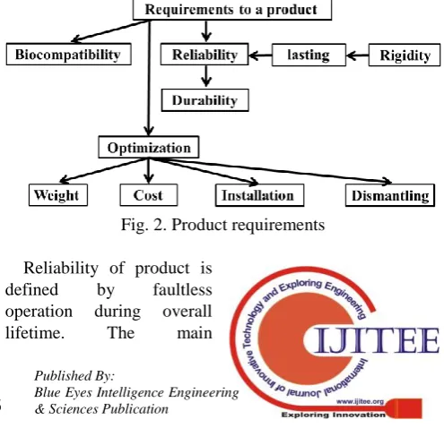
Fig. 1. Stages of development of transpedicular fixator Engineering and medical specifications include requirements illustrated in Fig. 2. Biological compatibility is determined by selection of material. These requirements are satisfied by such materials as ceramics, polymers, metallic alloys, composite materials. Application of titanium nickelide is described in details in [1].
Fig. 2. Product requirements
Reliability of product is
defined by faultless
operation during overall
lifetime. The main
Optimization and Mathematical Simulation of
Transpedicular Fixator
[image:1.595.302.550.599.838.2]parameters of reliability are strength, rigidity, quality of interconnection of fixator parts and of fixator with bone elements. Since during sufficiently long time of tissue regeneration fixator performs certain function, it is required to provide dynamic strength. Rigidity of fixation of sound vertebras depends on the sizes of transversal cross sections of fixator elements, absence of movements both between connected fixator parts and between fixator screws connected with bone tissue. Decrease in rigidity can be caused by destruction of bone tissue upon interaction between fixator screw and vertebra. This phenomenon can be controlled by varying geometry of screw and thread, decreasing stress in bone tissue, replacement of screw V-thread with round thread together with filling the space between screw and bone tissue with biocompatible mix. Modulus of elasticity of filling mix should be somewhat lower than that of compact bone tissue. This would permit to decrease contact stresses and round thread will increase fatigue strength of screw.
Determination of allowable mobility of fixator–vertebras system is of interest since increase in rigidity leads to increase in fixator weight and cost.
B. Algorithm
According to the requirements (Fig. 3), let us consider reliability of the design and its junction with vertebras. In this case the system fails after achievement of ultimate state, that is, exhaust of carrying capacity in terms of strength or achievement of unallowable deformations. Simulation of reliability reflects transformation of random input parameters (impacts) into output parameters of dynamic system (stresses, deformations). Failure of any element is considered as system failure. Such system is referred to as nonredundant system [7]. Probability of faultless operation for such system is determined as follows [7]:
(1)
where is the random event: failure; n is the number of failure elements;i is the first element; П is the product operator.
Then, Eq. (1) can be rewritten as follows assuming independence of element failures for simplicity:
, (2)
[image:2.595.48.289.645.788.2]where is the random event for screws: failure; is the random event for screws–vertebra body junction; is the random event for longitudinal and transversal structure.
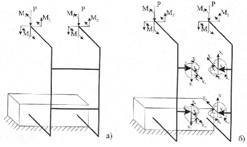
Fig. 3. Structural model of fixator based on force method External impact on fixator (patient own weight, dynamic action of muscles upon possible bending or some work) can be considered as stationary normal process. As mentioned in [7], this is justified by the fact that in case of combined action of sufficiently high number of random perturbations obeyed to various distribution laws without prevailing one, the distribution of resulting perturbation, according to central ultimate probability theory, is close to normal distribution.
In order to determine the absence of probability of ultimate state for each three elements, the equation from [7] is used for noncorrelated load and carrying capacity:
, (3)
where
is the function of normal
distribution in time; ŋ = ; is the mathematical
expectation of carrying capacity and load; ; ;
are the dispersions of load and carrying capacity, respectively.
Reliability is calculated by the method of successive iterations. At first the problem of system optimization in deterministic formulation is solved and then, using Eqs. (2) and (3) at obtained data for fixator design, the probability of absence of ultimate state is calculated by Eq. (3). In the case of design insufficiency, the respective design sizes are increased.
Violation of fatigue strength can be considered as ultimate state in terms of strength for screws and longitudinal–transversal design, that is, fatigue strength of material ; for screw–vertebra body junction, the yield strength for cement joining screw with vertebra body or for bone tissue without cement. Ultimate state in terms of deformation is determined by allowable mutual movements of vertebras (screws).
Let us consider optimum design of fixator in deterministic formulation. Optimum system is such an allowable system which is the best in terms of selected optimality criterion. In the course of optimization, the key issues are target function, criteria of optimization, restrictions, allowable systems, control functions. This work is aimed at development of optimum fixator design providing the required immobility of two vertebras for the regeneration period of bone tissue of injured vertebra.
The optimization parameters are geometrical sizes of fixator design, material grade with physicomechanical properties, loads, cost of material, cost of production, time of fixator assembling during operation, time of disassembling, internal forces in design elements, stresses in design elements, design deformation. The mentioned parameters can be subdivided into uncontrollable (invariable during optimization) and controllable (variable during optimization). All mentioned
multiparameter optimization. Such optimization is a complex process. Hence, while analyzing existing designs by experience and publications, let us reduce the number of controllable parameters.
Let us begin with fixator dimensions. It would be practical to subdivide all fixators into 3–4 typical sizes, each of different weight and cost. Each typical size is determined by screw interaxial spacing. Then it would be reasonable to joint longitudinal rods and transversal connectors rigidly, for instance, by welding. We exclude connecting elements, decrease weight of overall design, its cost, fixator assembling and disassembling time. According to Eq. (1), fixator reliability is improved due to decrease in .
Selection of material grade is related mainly with its biocompatibility. From this point of view titanium alloys proved to be good choice, however, they are characterized by such disadvantages as comparatively low fatigue strength. Therefore, attention is paid to composite designs. Fatigue strength of alloyed steel is nearly two-fold higher in comparison with titanium alloys. Upon implantation of high strength alloyed steels, harmful impact on organism by metal can be isolated using biocompatible composite coatings including nanomaterials. Possible coating can be made of biological cements which additionally improve combined operation of screw and vertebra body. Therefore, it is possible to use finite number of controllable variants for material. Stochastic essence of load can be reduced to deterministic variants according to previously selected typical sizes of fixator. Herewith, possible movement of patient should be taken into account: walking, bending, body turning.
Calculated flowchart of transpedicular fixator according to the force method is illustrated in Fig. 3. Here forces P, momentums , , are formed by patient weight, muscle forces, and inertia forces upon bending forward and leftward, body turning with acceleration [8]. All force factors in dynamics can be written using the coefficient of dynamicity:
, , (4)
where , are the static impact of load.
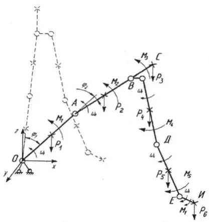
In order to determine the coefficients of dynamicity, let us carry out approximate dynamic simulation. Let us start from determination of kinematic model of supporting–motor apparatus. Human body is subdivided into segments [8]. Each segment is presented by a unit. Figure 4 illustrates kinematic diagram. Here the joint O (fixed) corresponds to invertebral disc at the level of thoracolumbar junction, the unit ОА – to middle thoracic section, the unit АВ – to the upper thoracic section, the point С – to the center of gravity of head, CD – to the shoulder, DE – to the forearm, EI – to the hand. The unit ОА has only rotating movement, and the other units – progressive and rotating movements. Figure 4 illustrates vertical position of human (dashed line), solid lines show bending forward; the angles are the angles of unit rotations; is the own weight of segments (the vectors are applied in the unit center of gravity); is the momentums of muscle forces rotating the units with regard to respective junctions;
is the angular speed of unit rotation.
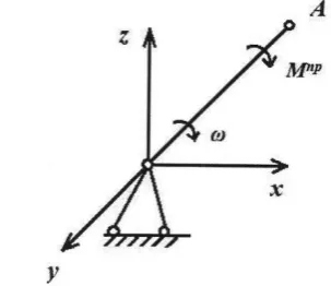
In order to determine force factors (Fig. 3), we rearrange the kinematic system (Fig. 4) to a simpler dynamic equivalent system (Fig. 5).
The unit ОА is selected for this aim which forms the lowest kinematic pair with the reduced momentum or with the force . It is known that the power of mechanic system upon progressive or rotating movement is determined as follows:
, , (5)
[image:3.595.323.532.244.466.2]where М is the momentum rotating the unit; Р is the force performing progressive movement of the unit; is the unit angular speed; V is the point linear speed where the speed P is applied; cosP^V is the angle between the vectors P and V.
Fig. 4. Kinematic structure of human.
Then, equating the powers (on the basis of energy preservation principle) of two systems (Figs. 4 and 5), we obtain the following:
cos(
(6)
where is the force of gravity of the i-th unit; is the momentum of force action of body muscles and upper extremities together with inertia forces; is the speed of center of gravity of the unit OA; is the angular speed of the i-th unit; is the inertia force of weight of the i-th unit concentrated in the unit
allow considering for angular movements of hand as rigid integer.
Fig. 5. Kinematic structure of reduced system In Eq. (6) we have two unknown variables and , and the other parameters for patient can be determined by the segments [8]. The speeds and are determined by experience or experimentally.
The second equation is obtained according to the law of preservation of total mechanic energy. If the system is impacted by external forces and it is transferred from one state to another, variation of total mechanical energy during this transfer equals to the work of external forces:
, (7)
where N is the power, and t is the time.
Hence, on the basis of equivalence of the two systems (Figs. 3 and 5) and with consideration for Eq. (7), we obtain the second equation:
,
where is the kinetic energy of the i-th unit.
Kinetic energy for each unit is calculated as follows:
,
Taking into account that
,
,
where is the weight of the i-th unit; is the momentum of weight inertia of the i-th unit with regard to the axis parallel to the y axis (Fig. 4).
Solving together Eqs. (6) and (7), let us determine the reduced dynamic momentum . Then, the coefficient of dynamicity, according to [8], is determined as follows:
, (8)
where is the static momentum of forces acting on human body above the section over injured vertebra with regard to axis in the vicinity of this vertebra.
Another parameter is stress. Quiet often upon development of optimum designs stress is considered as controllable, since with accounting for restrictions the sizes of design parts depend on it. Stresses depend on load, interaction of frame structure (longitudinal rods and connector), and screw–biological element–vertebra body system. Hence, in order to simplify calculations, it would be reasonable to consider these two systems separately. Using appropriate software for finite element calculations it is possible to solve problems in general.
[image:4.595.309.547.318.474.2]The works [1], [8]-[10] present statistical analysis of fixator for patient C using the force method. The system is presented in the form of rod-based frame (Fig. 3). Bending and torque diagrams are illustrated in Fig. 6. It follows from analysis of these diagrams that the most optimum geometrical shape of fixator rod is tubular. Tube performs well for torsion and stability, it is close to optimum shape upon oblique bending.
Fig. 6. Bending (a) and torque (b) diagrams
Fig. 7. Schematic view of fixator screws with regard to vertebras
Another controllable parameter is the fixator cost:
, (9)
where is the cost of material; is the cost of composite coating (if any); is the cost of production; is the cost of biological cement; is the cost of sterilization; is the cost of packing; is the cost of transportation; is the cost of installation.
Assembling or disassembling time can also be referred to as controllable parameters. It can be presented as the sum of subjective and objective times. Subjective time depends on surgeon qualification and the objective time – on fixator design. Let us optimize the time by analyzing the adopted prototype. The first disadvantage is the significant number of screw junctions. This increases total weight of fixator, production cost, assembling time. In addition, upon periodic impacts, the screw junctions without sufficient fixation (by implants, special discs) are characterized by violation of rigidity which will affect negatively the regeneration of bone tissue. Hence, it would be reasonable for 3–4 typical sizes to provide rigid (welded) joint of longitudinal rods and connector. Then, it is possible to eliminate thread junction of screws with longitudinal rods. With this aim the screw of special shape is made: the screw head is tubular and is installed onto longitudinal rod (as in the initial variant it can move along and to rotate with respect to axis of longitudinal rod), the angle (Fig. 7) is higher than 90°. The ends of longitudinal rods and the screw head have several pairs of through holes for screw fixation by pins. Application of biological cement eliminates necessity to install screw into vertebral body. With this aim the holes for screws in vertebra body are of higher diameters than that of sizes of screw transversal cross section.
Let finalize the analysis of optimization parameters. Fixator geometry is an uncontrollable parameter. We select welded design with longitudinal and transversal tubular rods, screws – with round thread and hyperbolic thread with fixation by pins. Discretely controllable parameters are load and mounting dimensions, material.
Controllable parameters are dimensions of transversal cross section of fixator parts, product cost.
Optimization (efficiency) criteria are two non-contradicting scalar criteria: weigh and cost:
, (10)
, (11)
where is the specific weight of the i-th material; are the geometrical sizes of the i-th element of fixator; is the weight of the i-th fixator; is the variables of production technology, sterilization, packing, transportation, see Eq. (9), j = 1, 2, 3, 4 is the numbers of anthropometric groups of patients.
In order to develop operable (allowable) fixator design, let us introduce the following restrictions. The first is the restriction for stressed state:
Max (x) , (12)
where is the equivalent stress for the i-th element of fixator design; x is the coordinate of cross section point of design element; is the allowable stress for the i-th element of design; is the ultimate fatigue strength of material with the coefficient of cycle asymmetry is the function of reserve of fatigue strength depending on coefficient of concentration of scale factor, surface quality, element responsibility.
Equation (12) formulates the condition of fatigue strength. The second restriction is the deformed state, that is,
, (13)
where is the angle variation illustrated in Fig. 7 as a function of load; is the angle variation between the axes of screws in perpendicular to sagittal plane illustrated in Fig. 7 as a function of load; is the twisting angle of frame of fixator longitudinal and transversal rods; allowable calculated values in order to provide regeneration of bone tissue are given in brackets.
The third restriction is restriction of transversal cross sections of screws, that is:
, (14)
The allowable diameters are determined by maximum allowable value excluding injury of vertebral arches.
Optimum design is formulated as follows: it is required to determine in n-dimensional space such allowable point:
, ,
where optimum value of target function is achieved:
, x ,
where x is the controllable parameters of optimization; D is the allowable region with restrictions by Eqs. (12), (13), (14). As already mentioned, let us perform optimization separately for longitudinal and transversal system and for screws.
The target function for rod system is determined with consideration for efficiency criteria, Eqs. (10) and (11):
, (16)
where x is the controllable parameters; a, b are the weight coefficients (a+b=1); , are the prototype weight and cost, respectively.
Optimization is carried out separately for each anthropometric group of patients. Discrete optimization is performed for various materials. Then, in Eq. (16) for P(x) there is only one controllable parameter: external diameter of tubular rod with preset ratio of internal to external diameter.
We obtain in explicit form the sizes of rod transversal cross section. For elastic–plastic material according to the third theory of strength, the restrictive condition, Eq. (12), can be written as:
, (17)
where is the normal bending stress; is the
bending momentum (Fig. 4); is the momentum of resistance of rod transversal cross section area;
is the cross section external diameter; is the cross section internal diameter; = is the tangential stress;
is the toque (Fig. 6); .
From Eq. (16), taking into account , we have:
, (18)
where к .
Optimum k is determined by Eq. (15). In terms maximum
use of material, the ratio
should approach unity, that is, the stress of torsion and bending is significantly lower in the center of circular cross section. The restriction is the condition of stability of thin walled shell (tube) upon bending with torsion.
Then, in Eq. (16) we have P (x) , where V is the specific weight of material; C (x) is determined by Eqs. (9) and (11). Product quality depends on cost and increases with it, therefore, designer estimates result after preset of the weight coefficients а and в in (16).
Optimum sizes of fixator screws are obtained by solution of spatial problem of the theory of elasticity of heterogeneous system comprised of metal, biological cement and bone tissue. Optimization includes not only determination of screw sizes with consideration for Eqs. (12), (14), but also selection of elasticity modulus of biological cement which can be in
the range of ultimate modulus of screw and bone tissue materials.
Control function for rod system in Eq. (18) is the function of bending momentums and for screws – variation of stresses.
C. Flowchart
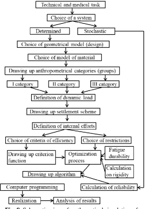
[image:6.595.311.546.161.500.2]The above mathematical description and development of patient–fixator system can be presented by flowchart of mathematical simulation of optimum fixator design (Fig. 8).
Fig. 8. Schematic view of mathematical simulation of optimum design of fixator
III. RESULTSANDDISCUSSION
The proposed mathematical model of optimum simulation of fixator considers for possible dynamic loads upon patient motion during rehabilitation, reliability based on theory of probability, cost range, fixator sizes peculiar for each patient.
IV. CONCLUSION
Combined use of system analysis and optimum designing makes it possible to develop optimum transpedicular fixator both in terms of application and in terms of cost. Design reliability would permit to use fixator for multiple times after biochemical treatment, which also reduces the item cost.
REFERENCES
1. K.S. Sergeev, M.F. Durov, V.I. Kucheryuk, and V.E. Gyunter, et al. “Khirurgicheskayastabilizatsiyaperelomovnizhnikhgrudnykhipoyasnich nykhpozvonkov” [“Surgical stabilization of fractures of basilar and
dorsal vertebras”]. Tyumen': Printmaster, 2005.
kyphosis”. Spine, vol. 18(13), 1993, pp. 1909-1915.
3. A. V. Antonov. “Sistemnyianaliz” [“System analysis”] Guidebook, 3rd edition. Moscow: Vyssh. Shk., 2008.
4. E.J. Haug and J.S. Arora,“Applied Optimal Design. Mechanical and Structural Systems”. John Wiley & Sons, Inc. The University of Iowa 1979.
5. O. Niels, “Optimal design of vibrating circular plates”. Internat. J. Solids and Structures, vol. 6(1),1970, pp. 139- 156.
6. G.I.N. Rozvany,“Optimal design of flexural systems: beams, grillages, slabs, plates and shells”. Oxford; New York; Toronto; Sydney; Paris; Frankfurt, 1976.
7. L.I. Volkov and A M. Shishkevich,“Nadezhnost' letatel'nykhapparatov” [“Reliability of aircrafts”]. Moscow: Vyssh. shk., 1975.
8. V.I. Kucheryuk and Yu.K. Shlyk. “Biomekhanikaimodelirovanie”
[“Biomechanics and simulation”] Guidebook.Tyumen’: TyumGNGU, 2009).