International Journal of Innovative Technology and Exploring Engineering (IJITEE) ISSN: 2278-3075, Volume-8 Issue-7, May, 2019
Abstract: Abstract: The objective of the work was to present a robotic design to rescue a child from a bore well. The project has been focused on overcoming the challenge of digging a parallel hole in rescue operation. The rescue robot was modeled with two robotics hands, two sensor gloves, hydraulic fixer, camera and sensors. The rescuing operation of this robot functions using Haptics and Lora technologies. To get proper gripping action, end effectors similar to humanoid fingers were used. The robot conceptual design was developed in accordance with bore well dimensions, whose operating space could be adjusted with reference to dimensions. Children with less awareness of their surroundings get trapped by the bore wells, accidentally. Although the rescue operation is ongoing, many factors, such as lack of sufficient oxygen, rising temperature, cause another risk for child in such depth. Rescuing children from such situations is a challenging task. Without major risks, the proposed system rescues the child.
Index Terms: Haptics, Sensor Gloves, Rescue robot, Lora technology.
I. INTRODUCTION
In India, farmers depend primarily for agriculture on underground water. There is a decrease in underground water levels due to the increasing number of bore - wells being dug in the same region. Hence bore-wells get dried up frequently. In most of these cases the bore wells were left without closing. These abandoned bore wells have become death pits and have begun to take many innocent lives, particularly small children. Now a days children falling in bore wells is increasing because of the children's carelessness and playful activities. The holes dug for the bore wells are approximately 800 feet deep. The existing system that the rescue team is using to move toward the victim through a parallel well is not only difficult to save the victim's life, but also very risky [1]. A small hindrance in rescue operation may even cost a child's life. The lack of oxygen in the deep hole makes long survival impossible for the child. These process results 80% of the rescue operations fail. A lot of time and money is spent in these missions.[2] Although the required rescue operation is performed, numerous factors such as deficiency of oxygen, high temperature and humidity in the depth will pose another risk to the victim.[3] Not many of the victims have been saved in this scenario. Some
Revised Manuscript Received on May 06, 2019
Seeram Srinivasa Rao,Professor, Department of Mechanical Engineering, Koneru Lakshmaiah Education Foundation, Guntur, India.
Nagula Srikanth, Student of M.Tech in Mechatronics, Department of Mechanical Engineering, Koneru Lakshmaiah Education Foundation, Guntur, India.
self-governing robots have been developed to rescue the trapped child from bore well.
The proposed system is based on Haptics technology. It is a tactile feedback technology that uses touch sensitivity by applying forces, vibrations or motions to the user. Lo Ra technology is used to communicate wirelessly from base to ground station. This mechanical simulation is used to help create virtual things in a computer simulation, control virtual objects of this kind and enhance remote control of machines and devices. Haptics devices can incorporate on the interface tactile sensors that measure the user's forces. By allowing the design of cautiously controlled Haptics virtual objects, this technology made it feasible to look into how the human sense of touch works. These objects are used to test the human Haptics capabilities steadily, which would be difficult to achieve otherwise. Robotics includes mechanical and electrical engineering elements as well as control theory, computing and now artificial intelligence. In the robotic arm, in addition to the elbow, and wrist, the arm has several joints, similar to a human arm, coupled with the joints of the fingers, there are many joints. In engineering systems, Haptics environment is used to create virtual environment[4]. It incorporates tactile feedback technology by applying motions, vibrations or forces by the user to measure the sense of touch.
Haptics can be broken down into three areas:
1. Human Haptics: It is the study and control of human sensing by touch & motions.
2. Machine Haptics: It is designed, built and used to replace human interference with machines.
3. Computer Haptics: Developing algorithms and software related to the generation of virtual objects touch and motion. The main idea is to create electrical signals on the Haptics device through the sensors that work as transducers and convert hand movements into electrical signals[5]. These movements of the hand will control the robotic arm's motion. Research is done to develop principles for the realization of advanced Haptics interaction robotic and human - machine systems.
II.LITERATURESURVEY
B.Bharathi et-al described a Human controlled robot how to safely rescue the baby and steps taken to achieve, the robot can move inside the pipe according to the user's commands from the PC.
Modeling and Analysis of Bore well Rescue
Robot Using Haptics and Lora Technology
The project also used object selection and placement based on the design of the arm. The robot is operated via PC using Zig bee wireless technology and wireless camera, we can view both audio and video on the monitor.[6]
B.Shahina,P.Suji et-al described Smart Bore Well Rescuing Robot using Arduino Uno microcontroller for controlling the ultrasonic sensor, sensor is Used to measure the distance at which the victim is present, this ultrasonic sensor displays in both meter and centimeter on the LCD display. The Rescue unit comprises of two DC motors, a Web camera and a LED light[7]. Web camera is associated with the PC to see the status of the child inside the bore well. A motor driver (L293D) is used to drive two DC motors, One DC motor is utilized for the flat and vertical movement of the rescue unit and another DC motor is utilized for the open and close movement of the rescue unit.
S.Arthika et-al proposed an arrangement of structuring a customizable width robot for the salvage of a kid from bore well. It helps the kid by nonstop checking using camera and supply of important things mainly, air filler which supplies oxygen for the survival. This framework will attach a outfit to kid utilizing automated arms for picking up. [8] To calculate the distance, they are using infrared transmitter and a temperature sensor is utilized to calculate temperature and gas sensor is to recognize the presence of any poisonous gas. The proposed system will effectively salvage the kid without major injury.
Shruthi et-al described the open bore well robot having a controlling unit and a monitoring unit. The controller controls and allows the robot to move into the borehole with the motor's pulley action. With the help of a camera, the monitoring unit monitors the movement of the robot and the condition of the child trapped in the bore hole. The high - end camera module used here will have an ambient light system that supports the rescue process as the robot moves into the bore hole. Other characteristics of the robots that support the child's maximum safety include the oxygen concentration unit and airbag. The whole unit is intended to work in double mode both utilizing power supply and battery mode.[9]
Albert Francis et-al described child rescues from bore well with two mechanisms controlled by two motors for the rescuing of the kid from the bore well. One motor controls the mechanism to find posture and other motor to control and getting a handle on system. Child visualization is possible with the use of high - resolution infrared camera and TV monitor. This light weight machine can go without much of a stretch into the drag well and spare the caught kid. [10]
III.DRAWBACKSOFEXISTINGSYSTEM
In general, an equivalent hole is created to reach the child and then a horizontal path is created. But it takes lots of time to save the child's life. It also requires a huge amount of
takes about 24 to 72 hours to dig, by that time there is less chance of child being rescued alive.
IV.CONSTRUCTIONOFDEVICE
Construction of rescue robot is mainly divided into four components
4.1. FIXING COMPONENT 4.2. ROTATING COMPONENT 4.3. GRASPING COMPONENT 4.4. SUPPORTING COMPONENT
3.1. FIXING COMPONENT:
To improve the stability, a double acting hydraulic fixing element is employed with cylinder and piston arrangements. The expansion of the two pistons fix to the walls of the bore well, providing stability to the robot, where as contraction gives free movement to it as shown in Fig 4. This fixing arrangement plays a vital role in the rescue process.
3.2. ROTATING COMPONENT:
The principle reason of actualizing the round disk is to pivot the robot to address position as per the child's posture. To rotate the disc, internal spur gear mechanism is employed.
3.3. GRASPING COMPONENT:
The grasping unit consists of two robotic hands, a micro controller, a transceiver, servo motors, and sensors. The action of holding the child is controlled with this unit.
3.4. SUPPORTING COMPONENT:
The air balloon is used as the supporting system. It supports the child if slipped from the robotic hands accidentally.
V.PROPOSEDSYSTEM
To overcome the drawbacks of the present system, a new system is proposed to prevent children from falling into bore well. The system consists of two robotic hands, two gloves, Flex sensors, microcontroller, and SX1278 LORA wireless transceiver. The design of the robot is done in solid works shown in Fig 1
.
5.1 CAMERA:
A wireless night vision camera is employed to visualize the position of the child trapped in the bore well.
5.2 OXYGEN:
A supply pipe is attached to the rope, which provides oxygen to the victim.
5.3 PIR SENSOR:
Passive Infrared sensor is used to detect the radiations emitting for the victim’s body, which shows whether the child trapped in the bore well is alive.
5.4 ULTRASONIC SENSOR:
International Journal of Innovative Technology and Exploring Engineering (IJITEE) ISSN: 2278-3075, Volume-8 Issue-7, May, 2019
The Sensor module consists of ultrasonic transmitter, receiver and control unit. Ultrasonic sensor emits acoustic waves between 20Hz to 20 kHz and determines the distances. 5.5 DRUM:
Drum is used to store wires, Arduino. 5.6 FINGERS:
With the actuation of servo motors, fingers move to hold the child.
5.7 PRESSURE SENSOR:
Pressure sensor is used to let the operator know, with how my pressure the child is being held with the fingers. PULLEY AND ROPE:
The ISO standard rope and pulley are used for the operation.
Fig1: Description of robot
1. Pulley 2.Rope 3.Drum 4.Motor 5.Hydraulic fixer 6. Camera 7.Fingers
5.8 ARDUINO LEONARDO:
The Arduino Leonardo is a microcontroller board supported the ATmega32u4. it has twenty digital input/output pins (of that seven is used as PWM outputs and twelve as analog inputs), a usb connection, a power jack, 16 MHz crystal oscillator as shown in Fig 2 .It contains everything required to support the microcontroller; simply connect it to a laptop with a USB cable and power it with a AC-to-DC adapter or battery to get started. The Leonardo has a number of facilities for communication with a pc, another Arduino, or alternative microcontrollers.
Fig2: Arduino Leonardo 5.9 MONITOR:
A monitor displays the visuals of child, outputs of the PIR and Ultrasonic sensors.
5.10 FLEX SENSOR:
Flex sensor is employed to determine the measure of diversion (or) twisting. This sensing element has 2 output wires one is connected to power supply and another is connected to ground. When the device is twisted, the resistance between two wires increases in proportion to the bending quantity. Elements of carbon resistance are present in the sensor.
Fig3: Flex sensor 5.11 HYDRAULIC FIXER:
Double acting Piston cylinder arrangement gives stability to the robot
.
5.12 ROUND PLATE:
To adjust the robotic hands suitable to hold the child in the bore well, round plate of 200 mm diameter with internal spur gear mechanism is used.
5.14 TRANSCEIVER:
The SX1278 transceiver receives the input from aurdino and sends data wirelessly to SX1278 transceiver present at the underground station.
5.15 SERVO MOTOR:
MG996R servo motors are using which each motor can resist 10 kg torque as shown in Fig 5. Five servo motors are using in these robot first one for rotating the circular disc and second one for controlling of thumb finger on left hand, third one for controlling of rest four fingers with one D.O.F on left hand, fourth for controlling of thumb finger on right hand, fifth for controlling of rest four fingers with one D.O.F on right hand. The servo motors consist of three wires Red is for power, yellow/white is for signal and black/brown is for ground.
Fig5: Servo Motor
VI.WORKING
Step-1: The pulley and rope arrangement is placed on the surface of the bore well. The robot is attached to the end side of the rope and sent into the bore well by manual operation.
Step-2: The live visuals of the camera are watched on the monitor. Once the robot reaches the victim, the rope is stopped and fixed by the hydraulic fixers.
Step-3: PIR sensor detects the radiations emitted from the victim’s body and gives the output on the monitor whether the target is alive or not. The depth of the victim trapped in the bore well is found out using Ultrasonic sensor. Depending on the depth, the availability of oxygen levels is estimated. If required, oxygen is supplied with the help of pipes.
Step-4: The round plate is adjusted by the operator through wired control, until it matches the suitable position of the victim.
Step-5: The operator wears the sensor gloves and the rescue operation starts with this step.
Step-6: Flex sensors attached to the gloves, generates input
Step-7: The transceiver receives data and gives input to the Aurdino-2. This actuates the servo motors, moving the robotic fingers to grasp the child.
Step-8: The fixers are released and the robot vertical movement is altered as per requirement by the operator.
Step-9: Once, the child is completely held in the robotic hands, the rope is completely pulled up, so that the child reaches the surface level.
Fig6: Design of Robot
This robot is mainly divided into two sections Sensor Gloves and Robotic hand.
VII. SENSORGLOVES
The sensor gloves setup consists of Six Flex sensors, Arduino Leonardo, power supply, voltage divider shown in
Fig: 7. the flex sensors are positioned on the fingers and wrist. Once the sensor glove senses the motion, the resistance changes and the values are given to voltage divider. The voltage divider will convert the change in resistance to change in voltage that can be read by Arduino Leonardo. The analog to digital converter which is present in Arduino Leonardo will convert those analog signals to digital signals and sends the values to SX1278 transceiver.
International Journal of Innovative Technology and Exploring Engineering (IJITEE) ISSN: 2278-3075, Volume-8 Issue-7, May, 2019
VIII.ROBOTICHAND
The robotic hand consists of five servo motors, pressure sensors, power supply, and Arduino Leonardo as shown in
Fig 8. The SX1278 transceiver which is present in underground receives the values from transceiver-1 and actuates the servo motors. The tip of the fingers is connected with servo motor through strings. Two strings for each finger are fundamental, since one of them will be in charge of deviation, while the other is its length. The bending and opening the fingers action is carried by two strings respectively. The pressure sensor present on the robotic hand detects with how much pressure the child is being held.
FIG8:BLOCK DIAGRAM OF ROBOTIC HAND
IX. HAPTICSTECHNOLOGY
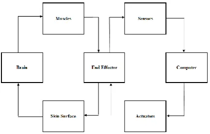
Haptics provide sense of touch with PC generated environments. Haptics mainly consists of two parts Human part and Machine part. The human part operates the hand position while the machine part simulates the connection with virtual objects by using force from the hand. Our body is controlled by the brain. Different parts of our body are given different instructions. The brain instructs the muscles to provide the End-effectors a specific input. The end effectors could be a sensitive Haptics device. It has varied sensors that sense the modification in angle, amount of force applied and provides this information to the pc. The computer then processes this information and gives specific instructions to an actuator. The actuator is an automatic action - placing device. The actuator then applies strength to the Haptics device, which is supposed by the user as a feedback force.[13] The feedback force is felt on the surface of the skin and this sense is taken by the brain. This can be the basic operating cycle of Haptics as shown in Fig 9.
Haptics refers to two kinds of information:
1) Tactile information: This references the data collected by the sensors connected to the user's body.
2) Kinesthetic information: This references the data obtained by the joints through the sensors.
Fig9: Block diagram of working Haptics
X.LORATECHNOLOGY
At present, there are several wireless communication standards within the market, which might be divided into small, intermediate and long distance wireless communication such as Zig bee, Bluetooth, WI-Fi, GPRS. Their distances of communication and rate of transmission are proportional to each other and the power utilization is also proportional to the communication distance. The Lo Ra technology free by Semtech Company completely solves the matter of communication distance and power utilization, which might achieve long distance communication below low power utilization. The advantage of Lo Ra within the transmission distance makes it very easy to create a long distance sensor network.[14] According to the necessities of data transmission distance and low power utilization, a wireless network supported Lo Ra technology was projected. The SX1278 transceiver was used as a RF module to transmit and obtain data in combination with GPRS module to the INTERNET network. [17]The SX1278 transceiver as shown in Fig 10 is used to communicate wirelessly from base to ground station.
Fig10: SX1278 transceivers
[image:5.595.315.532.56.194.2]XI. SIMULATIONRESULTS
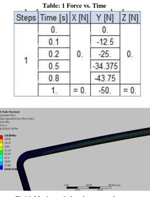
The child may weight around 20 to 30 kgs (200 N to 300 N), age ranges around 5 to 9 years. In order to analyze the stress distribution of the robotic hands, a weight of 50 N is imposed on each finger. Maximum induced stress in the arm is 13 N/mm2 when compared with yield strength of material 280 N/mm2. At a closer look we can see that fingers experiences maximum stress. The graph shown in Fig 13
represents the amount of force acting on the hand while holding the child with respect to the time. Maximum induced stress on the rope is shown in Fig 14.
Fig11: Maximum induced stress on fingers
Fig12: Total deformation
[image:6.595.308.547.48.362.2]Force vs time curve:
Table: 1 Force vs. Time
Fig14: Maximum induced stress on the rope
XII. CONCLUSION
The conclusion is that the rescue robot can give the fastest and safest way to rescue trapped victims in bore wells. This system is intended to conquer the disadvantages of present conventional bore well rescue systems. Here the proposed system consists of sensor gloves, robotic hand, Lo Ra transceiver, Haptics technology and sensors, which perform their operations. From the practical model and the analysis, we realize that the robot can catch and hold the child firmly, so we can save the victim successfully with the rescue robot. If this was successfully developed as a prototype, this could save many victims trapped in the bore wells.
REFERENCES
1. G. Kavianand, G., K. Gowri Ganesh, and P. Karthikeyan. "Smart child
rescue system from (SCRS)." In 2016 International Conference on Emerging Trends in Engineering, Technology and Science (ICETETS), pp. 1-6. IEEE, 2016.
2. Chaitra C, Kavyashree K, Athulya A, Aswanth Nambiar, Guruprasrd U “
Child detection and rescue system for bore well accidents”, In International Journal of Computer Engineering and Applications, Volume XII, Special Issue, June 18, www.ijcea.com ISSN 2321-3469.
3. Nithin, G., G. Gotham, G. Venkatachalam, and S. Narayanan. "Design and
simulation of bore well rescue robot-advanced." ARPN Journal of Engineering and Applied Sciences 9, no. 5 (2014): 3101-3104.
4. Deepak Jaiswal1, Sanjay Kumar1, Shishir Murthy1, Prashant Tiwari1
Shiva Kumara P2, Dr KS Badarinarayan3. “Haptic Robotic Arm (Wireless) ".International Research Journal of Engineering and Technology (IRJET) Volume : 03 Issue: 06 | June-2016 e-ISSN: 2395 -0056.
5. Krishna, R., G. Sowmya Bala, S. Sastry ASC, B. Bhanu Prakash Sharma,
International Journal of Innovative Technology and Exploring Engineering (IJITEE) ISSN: 2278-3075, Volume-8 Issue-7, May, 2019
6. Bharathi, B., and B. Suchitha Samuel. "Design and Construction of Rescue Robot and Pipeline Inspection Using Zig bee." International Journal of Scientific Engineering and Research 1, no. 1 (2013).
7. Suji, Ms P., Ms B. Shahina Farhin, Ms N. Sheikh Chandini Ramijha, and
Mr. G. Jayaraman. "Smart Bore well Rescuing Robot."
8. Arthika, S., S. Chidammbara Eswari, R. Prathipa, and D. Devasena. "Bore
well Child Fall Safeguarding Robot." In 2018 International Conference on Communication and Signal Processing (ICCSP), pp. 0825-0829. IEEE, 2018.
9. Shruthi H O1, Divyashree G2, Bindu A Thomas3, . "Open Bore well Rescue Robot" in international journal of recent trends in engineering and research issn 2455-1457.
10.Albert Francis A, Anbalagan D, Balachandran C, . "Child Rescue From
Bore wells" South Asian Journal of Engineering and Technology Vol.3, No.3 (2017) 63–70,ISSN No: 2454-9614.
11.Madhankumar, S., and K. Manonmani. "Design of Bore Well Rescue System using Morphological Chart." IJSTE - International Journal of Science Technology & Engineering, Volume 3 | Issue 06 | December 2016 ISSN (online): 2349-784X.
12.Kumar, G. N. S. and A. Srinath. 2018. "An Ergonomical condition’s of Pedestrians on Accelerating Moving Walkway: A People Mover System." International Journal of Mechanical and Production Engineering Research and Development 8 (Special Issue 7): 1376-1381. www.scopus.com.
13. White, Brian, Phillip DeSante, Thomas Trask, and Daniel Cox.
"Development and Implementation of a Mechatronic Haptic Hand System." In Proceedings 27th Annual Florida Conference on Recent Advances in Robotics (FCRAR 2014). 2014.
14.Daud, Shuhaizar, Teoh Shi Yang, Muhamad Asmi Romli, Zahari Awang
Ahmad, Norfadila Mahrom, and Rafikha Aliana A. Raof. "Performance Evaluation of Low Cost LoRa Modules in IoT Applications." In IOP Conference Series: Materials Science and Engineering, vol. 318, no. 1, p. 012053. IOP Publishing, 2018.
15.https://www.fasttech.com/product/5599000-lora-sx1278-long-range-rf-wi
reless-module
16.https://www.faranux.com/product/arduino-leonardo-board/
17.Bharat Satya Kumar, Y., Kalyan Chakravarthy, Y., Paladagu, R.P.,