International Journal of Innovative Technology and Exploring Engineering (IJITEE) ISSN: 2278-3075,Volume-8 Issue-6, April 2019
Abstract: Low Frequency Oscillations (LFO) happen in power frameworks on account of absence of the damping torque so as to strength to control framework unsettling influences as variation in mechanical information control. In the ongoing past Power System Stabilizer (PSS) was utilized to soggy LFO. Realities gadgets, for example, brought together Unified Power Flow Controller (UPFC), can control stream and augmentation transient dauntlessness. So UPFC can be employed to unexpected LFO in its place of PSS. UPFC damps LFO (Low Frequency Operation) concluded straight control of voltage and power. The fundamental essential component in planning and overhauling electric lattice framework is utilizing the transient dependability. The primary reason for this article is understanding and dissecting the transient steadiness of the Power System. The transient dependability is broke down on the IEEE 14-transport framework and its execution is watched utilizing the matlab reproduction. Recreation is performed for different kinds of burdens and for various unsettling influences. Reproduction results exhibit that the created PI damping controller would be increasingly successful in damping electromechanical motions.
Index Terms: Unified Power Flow Controller (UPFC), Low Frequency Oscillations (LFO), PI damping controller, 5 Machine-14 Bus power systems.
I. INTRODUCTION
The Welfares of Flexible AC Transmission Systems (FACTs) utilizations to progress the control frameworks security are outstanding [1], [2]. The development of the interest for electrical vitality prompts stacking the transmission framework close as far as possible. In this way, the event of the LFO has expanded.
Realities controllers have ability to governor organize conditions rapidly then this element of FACTs may also be utilized to expand control framework dependability. The UPFC is a FACTS gadget that may be utilized for the LFO. The essentially utilization of the UPFC is to regulate the power stream in the power frameworks. UPFC contains 2 voltage supply converters (VSC) all of those has 2 manipulate parameters [3]. The UPFC employed for power stream control, redesign of transient relentlessness, lightening of
Revised Manuscript Received on April 07, 2019.
M.Bhanu Prakash, B.Tech,Dept. of Electrical and Electronics Engineering,KLEF, Vaddeswaram, Guntur,INDIA.
N.V.Harshini, B.Tech,Dept. of Electrical and Electronics Engineering,KLEF, Vaddeswaram, Guntur,INDIA.
Sk.Moulali, Asst. Professor, Dept. of Electrical and Electronics Engineering,KLEF, Vaddeswaram, Guntur,INDIA.
K.V.Siva Reddy, Asst. Professor, Dept. of Electrical and Electronics Engineering,KLEF, Vaddeswaram, Guntur,INDIA.
structure movements and voltage rule [3]. The total and purposeful procedure for logical showing of UPFC for stable state and little banner dynamic examinations has been suggested in [4-7]. The further adjusted linearized Heffron-Phillips model of a power system presented with UPFC is shown in [8] and shown in [9]. The systems that are without power system stabilizer (PSS), amazing hampering can be practiced by methods for appropriate controller structure for parameters UPFC. By organizing a sensible UPFC controller, an incredible damping can be practiced. It is ordinary that Heffron-Phillips show is used in power structure to think about little banner soundness. This model has been used for quite a while giving strong results [10]. In this examination, applying fake neural systems has numerous focal points, for example, the capacity of adjusting to changes, adaptation to internal failure ability, recuperation ability, High-speed handling as a result of parallel preparing and capacity to assemble a VLSI Technology based DSP chip. Mat lab toolkits are utilized as a processing apparatus to execute the PI. To demonstrate execution of the structured versatile counterfeit neural system controller, a customary lead-slack controller which is planned in [11] is utilized and the reproduction results aimed at the power framework comprising these 2-regulators are contrasted and one another.
II. FLEXIBLE ACTRANSMISSION SYSTEMS
Adaptable AC Transmission Systems, alluded to as FACTS, arrived the ongoing years a standard term for advanced controllability in the power frameworks by recommends that of intensity electronic devices. Some of the FACTS-gadgets are offered for various uses around the world. In the majority of the uses the controllability is employed to maintain a vital separation from esteem serious or section needing augmentations of intensity frameworks, for instance like overhauls or increases of substations and electrical cables. Actualities gadgets give an obviously better adjustment to differed operational conditions and improve the use of the present creations. The essential usages of FACTS-devices are:
Analysis of the Transient Stability on IEEE
14-Bus System using UPFC damping control
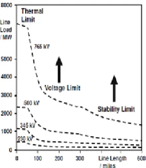
Fig. 2 shows the fundamental believe of FACTS for transmission systems. The utilization of lines for vibrant power transmission should be in a perfect world as far as possible. The Voltage and steadiness limits will be moved with the proposes that of the numerous very surprising FACTS gadgets. It will be seen that with evolving line length, the shot for FACTS gadgets gets a ton of and a great deal of imperative. The influence of FACTS-devices is talented through replaced or measured shunt compensations, arrangement compensations or part moves the board. The devices work electrically as speedy flow, voltage or impedance controllers. The power electronic allows horribly short response times directly down to path under one moment.
Fig 2- transmission lines Operational limits for altered voltage levels
2.1. Shunt Devices
The maximum employed FACTS-devices is the SVC or the rendition with Voltage supply gadget alluded to as STATCOM. These shunt devive zone unit in task as receptive control compensators. The most applications in transmission, circulation and modern systems are:
• Fall of undesirable receptive power streams thus decreased system misfortunes.
• Keeping of composed understanding force trades with adjusted responsive power.
• Reimbursement of clients and advance of intensity quality particularly with Brobdingnagian interest vacillations like modern machines, metal liquefying plants, railroad or underground train frameworks.
• Reimbursement of Thyristor converters for example in run of the mill HVDC lines.
• Development of static or transient solidness.
Practically 1/2 the SVC and quite 1/2 the STATCOMs area unit used for industrial applications. Trade further as industrial and local groups of clients need control quality. A gleam light isn't any more extended acknowledged, nor territory unit intrusions of business forms outstanding to short power quality. Railroad or underground frameworks with Brobdingnagian load varieties need SVCs or STATCOMs.
2.1.1 SVC
Electrical hundreds each generate reactive power and captivate reactive power. As the transmitted load differs significantly from 1 hour to a different, the reactive power balance during the grid varies further. The outcome will be unsatisfactory voltage sufficiency varieties or maybe a voltage despondency, at the intense a voltage breakdown.
A slash hack in task Static volt-ampere Compensator (SVC) will relentlessly offer the responsive power expected to governor dynamic voltage motions underneath various framework conditions and accordingly improve the capacity framework transmission and conveyance strength.
2.1.2
.STATCOM
[image:2.595.114.259.374.541.2]International Journal of Innovative Technology and Exploring Engineering (IJITEE) ISSN: 2278-3075,Volume-8 Issue-6, April 2019
2.1.3. Dynamic Power Flow Controller
Another device inside the space of intensity stream the executives is that the “Dynamic Power Flow Controller (DFC)”. The DFC might be a crossover gadget among a section shifting electrical gadget (PST) and exchanged arrangement pay.
A useful single line chart of the DFC. The DFC comprises of the ensuing segments:
•A regular part moving electrical gadget with tap-changer (PST).
•Series associated Thyristor Switched Capacitors and Reactors (TSC and TSR)
•A consequently exchanged shunt capacitance (MSC). (This is ideal looking on the framework receptive power prerequisites).
2.2. UPFC controller
This UPFC may be a grouping of both static shunt compensator and a static series compensator. It actions as a shunt compensating device and a part shifting device at the same time.
Fig.2.2 UPFC Principle configuration
The UPFC involves a shunt and a series electrical device, that square measure connected via 2 voltage supply converters with a standard DC-capacitor. The DC-circuit permits the dynamic power trade among shunt and arrangement electrical gadget to deal with the part move of the arrangement voltage gives the complete controllability to voltage and power stream.
The arrangement convertor must be ensured with a Thyristor connect. As a result of the high endeavors for the Voltage supply Converters and subsequently the insurance, AN UPFC is acquiring very high-ticket, that restricts the reasonable applications wherever the voltage and power stream the executives is required in the meantime.
2.3. Principle of UPFC
The essential pieces of the UPFC are 2 voltage supply inverters (VSIs) distribute a common dc stockpiling electrical gadget, and associated with the office framework through link transformers. One VSI is associated with in shunt to the transmission by means of a shunt electrical gadget, though the contrary one is associated sequential through an arrangement electrical gadget. An essential UPFC intentional topic is appeared in fig.2.3
Fig: 2.3 A simple UPFC purposeful scheme.
The series electrical converter is sorted out to embed a symmetrical 3 section voltage system of reasonable extent magnitude and point serial with the road to regulate active power and reactive power flows on the conductor. In this way, these electrical converters can trade dynamic and open power with the road. The open power is electronically given by the plan electrical converter, and likewise the dynamic power is transmitted to the dc terminals. The shunt electrical converter is worked in such some course on intrigue this dc terminal power (positive or negative) from the road keeping the voltage over the limit electrical contraption Vdc reliable. Thusly, the web real influence ingested from the road by the UPFC is comparable only to the incidents of the inverters and their transformers. Whatever is left of the limit of the shunt electrical converter is consistently accustomed exchange responsive power with the road in like manner to convey a voltage rule at the affiliation reason. The 2 VSI's will work severally of every unique by isolating the dc feature. hence for this situation, the shunt electrical converter is filling in as a STATCOM that produces or retains responsive capacity to deal with the voltage extent at the association reason. Rather, the arrangement electrical converter is filling in as SSSC that creates or ingests receptive capacity to deal with this stream, and along these lines the office low on the transmitter. The UPFC has a few potential operational modes. Uncommonly, the shunt electrical converter is working in such some approach to infuse a reasonable flow, ish into the conveyor. The shunt electrical converters are frequently controlled in 2 totally unique modes.
Control Mode of VAR: The reference or set point input is an inductive or electrical marvel volt-ampere ask. The shunt electrical converter the board deciphers the volt-ampere reference into a comparing shunt flow ask for and alters gating of the electrical converter to decide the required flow. For this method of the board a criticism flag speaking to the dc transport voltage, Vdc, is furthermore essential.
For this method of the executives, voltage criticism signals are gotten from the causing complete transport encouraging the shunt coupling electrical gadget.
The arrangement electrical converter pedals the extent and edge of the voltage infused sequential with the way to impact the office stream out and about. The specific cost of the infused voltage is regularly gotten from various perspectives.
Direct voltage Injection Mode: The set point inputs are directly the level and point of the series voltage. Phase Angle Shifter Emulation Mode: The set point input is area removal among the causing complete voltage and in this manner the accepting completion voltage. Line electrical opposition Emulation mode: The set point input is AN electrical obstruction cost to embed sequential with the street electrical opposition Automatic Power Flow the executives Mode: The set point inputs are esteems of P and letter of the alphabet to take care of on the conductor despite system changes.
2.4. UPFC Operation
The UPFC comprises of 2 change converters, that inside the usage thought of ar voltage supply inverters exploitation door turn-off (GTO) thyristors valves, as showed inside the Fig twenty four. These consecutive converters marked "Inverter one and "Inverter 2" inside the figure are worked from a run of the mill dc interface given by a dc stockpiling electrical gadget. This course of action works as AN air conditioner to air conditioning power gadget amid which the power will unreservedly stream in either heading between the air conditioner terminals of the 2 electrical converters and each inverter will severally create (or ingest) responsive power at its own air conditioning yield terminal.
Electrical converter two gives the most perform of the UPFC by infusing AN air conditioner voltage Vpq with reasonable greatness Vpq (0≤Vpq≤Vpqmax) and stage point
[image:4.595.305.518.451.566.2]street by means of AN addition electrical gadget. The infused voltage is reflected basically as a synchronous voltage supply. The conductor current moves through this voltage supply prompting genuine and receptive power trade among it and hence the air conditioner framework. the power changed at the air conditioner terminal (i.e., at the terminal of addition transformer) is conceived again by the electrical converter into dc control that looks at the dc interface as +ve or -ve genuine power requested. The receptive power changed at the air conditioner terminal is produced inside by the electrical converter.
Fig 2.4. Circuit arrangement of Basic UPFC.
The essential work of electrical converter 1 is to give or retain the imperative power requested by electrical converter a couple of at the regular dc interface. This dc interface control is conceived again back to air conditioning and coordinated to the link by means of a shunt-associated electrical gadget. Electrical converter one additionally can create or retain sensible receptive power, only if it's ideal, and there by it will give self-governing shunt responsive remuneration for the street. It is essential to see that wherever as there's a shut "direct" way for the critical power consulted by the activity of arrangement voltage infusion through Inverters one and a couple of back to the street, the relating receptive power changed is prepared or consumed locally by electrical converter a couple of and along these lines it doesn't move through the street. In this manner, electrical converter one might be worked at a solidarity control issue or be precise to have a responsive power trade with the street severally of the receptive power changed by the electrical converter a couple of. this infers there's no persistent responsive power move through UPFC
III. UPFC MODELED POWER SYSTEM
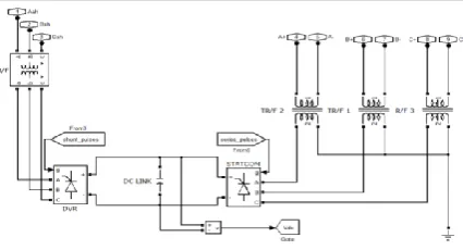
UPFC is one in everything about outstanding FACTs gadgets that is wont to improve establishment solidness. Fig.1 demonstrates a five machine-14-transport (SMIB) framework Heffron-Philips model of an impact framework put in with UPFC. It’s expected that the UPFC execution is predicated on heartbeat measurement balance (PWM) converters. In the figure one Maine, “mb and δe, δb “are the AM greatness connection and purpose of the mention voltage of each voltage supply gadget severally. These qualities are the info the executives signs of the UPFC controller.
Fig 3: simulation model with UPFC
As it referenced already, a linearized model of the power framework is utilized in unique investigations of intensity framework. So as to deliberate the impact of UPFC in LFO damping, the vigorous model of the UPFC is utilized; In this prototype the opposition and transient of the transformers of the UPFC dismiss be disregarded.
[image:4.595.62.273.643.765.2]International Journal of Innovative Technology and Exploring Engineering (IJITEE) ISSN: 2278-3075,Volume-8 Issue-6, April 2019
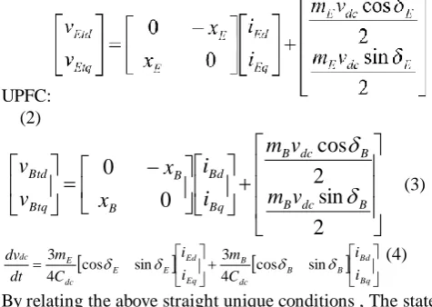
There leave a few models for UPFC relying upon a recent report cases. The accompanying condition depict the dynamic conduct of
UPFC: (2)
2
sin
2
cos
0
0
B dc B B dc B Bq Bd B B Btq Btdv
m
v
m
i
i
x
x
v
v
(3)
Bq Bd B B dc B Eq Ed E E dc E dc i i C m i i C m dtdv
sin cos 4 3 sin cos 4
3 (4)
By relating the above straight unique conditions , The state conditions communicated as pursues:
(5) Where the X and U matrixces are
Where ∆mE, ∆δE, ∆mB and, ∆δB are the deviations of UPFC regulator constraints reflected as state space model inputs
Th
e coefficients of k are attained by the Linearization of (1) and (2) about the operating point [6].
IV. STYLE OF DAMPING CONTROLLERS
4.1. Design of Lead-Lag Controller
As referenced previously, in this examination two distinct organizers have been utilized to sodden LFO. Among them first one is traditional lead-slack controller. It comprises of the gain block square, washout block square, lead-slack compensator block square. The washout square is considered as a high-pass channel, with the time steady TW. Without these square enduring changes in information would alter the yield. The estimation of TW isn't basic and might be in the scope of 1 to 20 seconds. In this examination, the parameters acquired from lead-slack controller structure that is displayed in [11], were utilized.
V. SIMULATION OUTCOMES
In this exploration, 2 distinct circumstances are contemplated. Out of this in the main circumstances mechanical power and in the second circumstances reference voltage has the step change and abnormality in and
deviation or change in rotor edge is watched. The parameter estimations of framework are assembled in Appendix. In first circumstances, step change in mechanical info control is examined. Reenactments are performed when mechanical info control has 10% expansion
[image:5.595.46.284.188.357.2]at t = 1s. Reenactment results for various kinds of burdens and controllers (ΔmE, ΔδE, ΔmB, ΔδB) and step change in mechanical info control are appeared in figures 3 to 7
Fig 3: 14 bus system with upfc
[image:5.595.302.544.420.544.2]Fig5: Angular velocity deviation during step change in mechanical input power for load
Thusly recreation results demonstrate that PI damping controller effectively increments the damping frequency and diminishes the sufficiency of low recurrence motions. Outcomes correlation between traditional lead-slack compensator and the suggested PI damping regulator for the UPFC shows that the recommended PI damping organizer has less or low settling time and low or less overshoot in examination with the ordinary PI compensator.
VI. CONCLUSIONS
This paper presumes that a Grid framework should contain exceptionally less blame clearing time to play out the capacity of the hand-off, when we separate the broken segment inside less time, the framework won't lose its synchronism and addition the security inside less time. Burden exchanging and the conduct of the three stage blame is investigates and watched. As per the investigation, the framework should have less blame clearing time and the heap exchanging techniques can likewise be gained for the getting the framework stability. As to UPFC capacity in transient security progress and damping LFO of intensity systems, a versatile PI damping regulator for UPFC was exhibited in this proposed paper. The regulator was intended for a solitary machine endless transport framework. At that point reenactment outcomes for the framework including PI damping regulator were contrasted and reproduction results for the framework including ordinary lead-slack controller. Recreations were completed for various types of burdens. Correlation demonstrated that the proposed versatile PI damping regulator has great capacity to decrease settling time and lessen plentifulness of LFO.
REFERENCES
1. N. G. Hingorani and L. Gyugyi, “Understanding FACTS: Concepts and Technology of Flexible AC Transmission System, ” IEEE Press, 2000. 2. H.F.Wang, F.J.Swift, “A Unified Model for the Analysis of FACTS
Devices in Damping Power System Oscillations Part I: Single-machine Infinite-bus Power Systems,”“IEEE Transactions on Power Delivery”, Vol. 12, No. 2, April 1997, pp.941-946.
3. L. Gyugyi, S.L. Williams, C.D. Schauder, T.R.Rietman, D.R. Torgerson, A. Edris, “The Unified Power Flow Controller: A New Approach to Power Transmission Control,” IEEE Trans., 1995, pp. 1085-1097. 4. Wolanki, D. McGillis, F. D. Galiana and G. Joos, “Mid-Point Sitting of
FACTS Devices in Transmission Lines,” IEEE Transactions on Power Delivery, vol. 12, No. 4, 1997, pp.1717-1722.
5. M. Noroozian, L. Angquist, M. Ghandari, and G. Anderson, “Use of UPFC for optimal power flow control”, “IEEE Trans. on Power Systems,” vol. 12, no. 4, 1997, pp. 1629–1634.
6. A Nabavi-Niaki and M R Iravani. “Steady-state and Dynamic Models of Unified Power Flow Controller (UPFC) for Power System Studies. ” “IEEE Transactions on Power Systems,” vol 11, 1996, p 1937. 7. K S Smith, L Ran, J Penman. “Dynamic Modeling of a Unified Power
Flow Controller. ”IEE Proceedings-C, vol 144, 1997, pp.7.
8. H F Wang. “Damping Function of Unified Power Flow Controller.” IEE Proceedings-C, vol 146, no 1, January 1999, p 81.
9. H. F. Wang, F. J. Swift, “A Unified Model for the Analysis of FACTS Devices in Damping Power System Oscillations Part I: Single-machine Infinite-bus Power Systems,” IEEE Transactions on Power Delivery, Vol. 12, No. 2, April, 1997, pp. 941-946.
AUTHORSPROFILE
M.Bhanu Prakash was born in Andhra Pradesh, India. He is pursuing bachelor’s degree in electrical and electronics engineering from KLEF, vaddeswaram, Guntur. His research interests include controlling the system,trasient
stability, power system, protecting of power system,.
N.V.Harshini was born in Andhra Pradesh, India. She is pursuing bachelor’s degree in electrical and electronics engineering from KLEF, vaddeswaram, Guntur. Her research interests include power system,protecting of power
system,controlling the system,trasient stability.
Sk. Moulali He is working as Assistant Professor in KLEF, Vaddeswaram, Guntur, Andhra Pradesh, India. He has received M. Tech degrees from Vignan University Guntur. He published 5 scopus and 10 international journal papers(non scopus). This author has overall 10 years teaching experience and guided more than 20 innovative projects as a part of his academic work. His research interests are power electronics, power electronics and
drives, power systems.