FABRICATED WITH DIFFERENT THICKNESS OF WAX SPACER – AN IN VITRO STUDY
Dissertation submitted to
THE TAMILNADU DR. M.G.R. MEDICAL UNIVERSITY
CHENNAI In partial fulfillment
For the requirements for the degree of
MASTER OF DENTAL SURGERY
BRANCH-I
PROSTHODONTICS AND CROWN & BRIDGE
First and foremost, I would like to express my sincere gratitude to my mentor Dr. C. A. MATHEW, M.D.S., for his continuous support, patience and words of motivation. This main dissertation work could not have been completed without his guidance through his immense knowledge. I am most grateful to have such a scholarly person as my advisor during my post-graduation period who remains to be an inspiration for me.
I extend my sincere thanks to our Principal, Dr. G. S. KUMAR, M.D.S., KSR Institute of Dental science & Research, for the facilities he has provided for the betterment of the students.
I would also like to thank my staffs Dr. VIDYA SANKARI, M.D.S., Dr. MUTHUVIGNESH, M.D.S.,Dr. SURESH, M.D.S., Dr. MAHESWARAN,M.D.S., Dr. RAJKUMAR, M.D.S., Dr. VISWANATHAN, M.D.S., Dr. RAJAGANESH, M.D.S., and Dr. GOUTHAM, M.D.S., for their constant suggestions and valuable guidance for all my work throughout the course.
forgot to.
I would also like to thank the non-teaching staff members and the technicians in our department and the staff members of the library for their kindness and cooperation in my journey as a post graduate student.
I would like to express my love and gratefulness to my grandmother and my uncle (Mrs.Sandha Andrews & Mr.Joseph Joy) for believing in me always and for making my dreams come true. I would like to thank my parents (Mr.Antonisamy & Mrs.Metty) and my siblings (Mr.Aju & Mr.Ciju) for supporting me throughout these years. And I would like to thank all my family members and my cousins for making my days a memorable one. I owe my sincere gratitude to Mr.Bharathi SCT founder, Dr. Anbuselvan MDS, Dr. Leo sujith Samuel, Dr. Ragavendran MDS., for helping me out to join the post graduation course in this esteemed institution. Without my family and friends, it could have not been possible for me to dream high.
My heartfelt thanks to my brother (Mr.Ciju) for financially supporting me throughout the course.
My sincere thanks to Dr. Lalitha, M.D.S., Department of public health dentistry, for her valuable guidance and suggestions during this main dissertation work.
S.NO TITLE PAGE NO.
1 INTRODUCTION 1
2 STATEMENT OF PROBLEM 5
3 AIM AND OBJECTIVES 6
4 NULL HYPOTHESIS 8
5 REVIEW OF LITERATURE 9
6 MATERIALS 28
7 METHODOLOGY 30
8 RESULTS 42
9 DISCUSSION 53
10 SUMMARY AND CONCLUSION 64
S.NO CONTENTS PAGE NO.
1 Materials 34
2 Devices 37
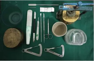
3 Armamentarium 38
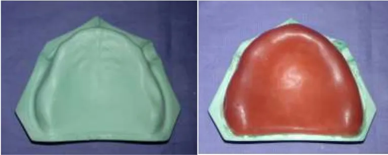
4 Maxillary edentulous model and 2mm uniform thickness wax spacer after adaptation
39
5 Conventional flasking and dewaxing procedure 39
6 Edentulous cast with soft liner 39
7 Duplication of maxillary analog with soft liner 40
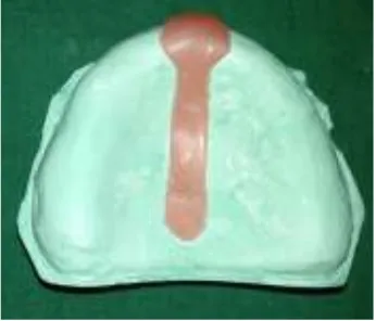
8 I shaped spacer design 40
9 Special tray fabrication with pillars 40
10 Putty index for fabrication of pillars 40
11 Metal gauge measuring 2mm Round bur 40
12 Device along with sensor positioned on analog 41 13 Digitally readings acquired after placing 2 kg weight 41
14 VPS group with double spacer 41
15 VPS group with single spacer 41
16 Polyether group with single spacer 41
S.NO CONTENTS PAGE NO.
1 Group statistics for initial pressure attained by both spacer thicknesses of the VPS group
43
2 Statistical analysis for comparison of initial pressure attained in both spacer thicknesses of the VPS group
43
3 Group statistics for final pressure attained by both spacer thicknesses of the VPS group
44
4 Statistical analysis for comparison of final pressure attained in both spacer thicknesses of the VPS group
45
5 Group statistics for initial pressure attained by both spacer thicknesses of the PE group
45
6 Statistical analysis for comparison of initial pressure attained in both spacer thicknesses of the PE group
46
7 Group statistics for final pressure attained by both spacer thicknesses of the PE group
47
8 Statistical analysis for comparison of final pressure attained in both spacer thicknesses of the PE group
47
9
Group statistics for comparison of pressure attained between the
VPS and PE groups for single and double spacer thicknesses 48
10 Statistical analysis for comparison of pressure exerted between the VPS and PE groups for single and double spacer thicknesses
S.NO CONTENTS PAGE NO
11 Group statistics for comparison of pressure attained on the crest region with vent hole and without vent hole for both single and double spacer thicknesses of VPS and PE group
51
12 Statistical analysis for comparison of pressure on the crest region with vent hole and without vent hole for both single and double spacer thicknesses of VPS and PE group
S.NO CONTENTS PAGE NO
1
Comparison between mean values of initial pressure attained
by both spacer thicknesses of the VPS group 43
2
Comparison between mean values of final pressure attained by
both spacer thicknesses of the VPS group 44
3
Comparison between mean values of initial pressure attained
by both spacer thicknesses of the PE group 46
4
Comparison between mean values of final pressure attained by
both spacer thicknesses of the PE group 47
5
Comparison of pressure attained between VPS group and PE
group for single and double spacer thicknesses 49
6
Comparison of pressure exerted on the crest region with vent hole and without vent hole for both the spacer thickness of VPS and PE group
VPS Vinyl polysiloxane PE Polyether
PMMA Polymethyl methacrylate FSR Force sensitive resistor Mpa Mega pascal
ANOVA Analysis of variance p Probability
SD Standard deviation df Degrees of freedom sig Significance level Fig Figure
[image:14.595.103.531.109.480.2]Impression making in complete denture Prosthodontics has transformed from the
carving of wooden and ivory blocks (that accommodated the intra oral contours), to
easier comfortable and more sophisticated methods in modern practice. Prior to 1600s
the complete denture replacements were not made, due to the lack of understanding,
of retention. The basic principles of complete denture impression making were
introduced in the middle of the 19th century, such as the concepts of maximum extension of denture-bearing area, atmospheric pressure, equal distribution of
pressure, and adaptation of the denture to the bearing tissues.1
The objective of impression making is to construct dentures with maximum retention
and stability without causing damage to the supporting structures.2 Impression is basically an interaction between the impression material and the tissues. There are
different theories in literature for recording the edentulous ridges with an impression.
The ideas that have been proposed over the years in relation to pressure applied are:
• No Pressure / Mucostatic theory
• Pressure / Mucocompressive theory
• Selective Pressure theory
Mucostatic theory:
Harry .L. Page in 1946, stated that all the soft tissues are chiefly fluid and 80% of the tissues are composed of water. According to Pascal’sLaw, “any pressure applied to a confined fluid is transmitted equally in all directions
and undiminished”. All these principles advocated that the Interfacial tension was the
INTRODUCTION
According to the principle of Mucostatics, the impression material should record all
the details of the mucosa without any distortion, so that a completed denture would fit
into all minute elevations and depressions.
Mucocompressive theory: This technique was initiated by the Greene Brothers. They were said to be the first to teach the closed mouth all modelling plastic
technique called the Greene Brothers all compound impression. The dentures
fabricated by this technique were in a continuous state of compression, creating poor
vascularity leading to resorption of the underlying bone. The opponents proposed
that a continuous functional state was not necessary in an artificial denture because it
remained only for a few minutes in a day.3
Selective pressure theory: This technique was advocated by Boucher in 1950. It combined the principles of both pressure and minimal pressure techniques. The
principle behind this impression technique was that the mucosa over the ridge area
was best suitable to withstand the pressure, whereas the area covering the midline was
thin and contained very little sub mucosal tissue. Hence, an equilibrium was created
between the resilient and non resilient tissues.3
Primary stress bearing areas of the maxilla are the crest of the residual alveolar ridge
and the horizontal slopes of the palatine bone and the secondary stress bearing areas
are the Rugae. Areas requiring relief are the incisive papilla, midpalatine suture and
tori areas in the maxilla. The non-stress bearing areas are to be recorded with least
amount of pressure, whereas selective pressure could be applied in certain areas of the
In edentulous patients, alveolar ridge mucosa is of variable thickness and mobility in
different areas. Due to the morphological differences in the hard and the soft tissues,
the pressure applied on the oral mucosa must be controlled or limited. Cortical bone
has the capability to bear functional load, whereas the residual alveolar ridges are
susceptible to resorption and cannot tolerate these loads.
Similarly, a keratinized, firm masticatory mucosa can resist the functional loads
whereas the non-keratinized mucosa and submucosa with lesser thickness cannot
tolerate such loads. Incisive papilla and mid-palatine raphe regions have low stress
bearing ability and the loads applied to these regions must be minimal to minimize
trauma.4
The consistency of impression material also affects the pressure applied to the
mucosal tissue beneath the denture base. Differences in properties of impression
materials enable the use of different methods to obtain better results. Appropriate
selection of impression material by a clinician should be entirely based on the oral
status, function and type of tissues, and mainly the handling skill of the operator.
Other factors that govern the impression pressure include the viscoelastic
characteristics of the impression material, the tray seating speed, the tray holding
pressure, and the contour of the tray.5
During rehabilitation of edentulous patients the mucosal tissues have to be recorded
with minimal distortion, and to achieve that, an appropriate impression technique and
a suitable impression material which has an optimal flow to obtain favourable
retention and stability of denture has to be used. Among the different impression
INTRODUCTION
in the literature. Duncan et al., states that the Selective pressure impression theory
provides the clinician with a method for improving the palatal adaptation of maxillary
complete dentures.6 Selective pressure could be enhanced by altering the spacer thickness, the spacer design and the materials used for making the impression. But the
spacer deign varies from one text to the other and there is no definitive explanation
for the thickness of the spacer to be used which leads to changes in the pressure
formed within a custom tray.3
Hence, the purpose of this study was to know whether the spacer thickness and the
materials used for impression making with a custom tray of similar tray and spacer
design(following the selective pressure theory), had any relation to the quantum of
pressure exerted on the denture foundation area, during impression making. The study
also evaluated if there was any significant change in pressure exerted on the denture
Following the Mucostatic theory, the denture foundation area will be recorded in a
static/ minimal compression form, resulting in a denture with compromised retention,
stability and esthetics. Whereas, when following the Mucocompressive theory, there
will be a constant pressure exerted on the denture foundation area, consequently
leading to resorption of the underlying bone.
Thereby, the Selective pressure theory has been recommended for making
impressions of edentulous residual ridges. Although various methods for making
impressions have been reported, a definitive procedure has not been clearly
elucidated.
This study, will evaluate changes in impression pressure produced by different
thickness of relief spacer and by different impression materials along with variable
escape holes in the impression tray for making an impression of a simulated maxillary
AIM OF THE STUDY:
This study was conducted with the following aims:
• To determine the amount of pressure exerted on different areas of a maxillary analog during secondary impression procedures, when using a similar tray and
spacer design, with different spacer thicknesses.
• To determine the amount of pressure exerted on different areas of a maxillary analog during secondary impression procedures, when using two different
impression materials.
• And also to evaluate whether the escape holes play a role in changing the pressure exerted during secondary impression.
OBJECTIVE OF THE STUDY:
Primary objective:
• To compare the pressure exerted on different areas of a maxillary analog during secondary impression procedure, using Vinyl polysiloxane material in
trays with similar design, with single and double spacer thicknesses.
• To compare the pressure exerted on different areas of a maxillary analog during secondary impression procedure, using Polyether material in trays with
similar design, with single and double spacer thicknesses.
• To evaluate and compare the amount of difference in the pressure exerted by both the impression materials in trays with similar design, with single and
Secondary objective:
• To evaluate the significance of vent holes in the difference of the pressure exerted during secondary impression procedure, in trays with similar tray
• There is no significant difference between the amount of pressure exerted on different areas of a maxillary analog during secondary impression procedures,
using Vinyl polysiloxane material in trays with similar design, with single and
double spacer thicknesses.
• There is no significant difference between the amount of pressure exerted on different areas of a maxillary analog during secondary impression procedures,
when using Polyether material in trays with similar design, with single and
double spacer thicknesses.
• There is no significant difference between the amount of pressure exerted by both the impression materials in trays with similar design, with single and
double spacer thicknesses.
• There is no significant difference in the amount of pressure exerted in the region of escape hole on the crest region, during secondary impression
procedure, in trays with similar design, with single and double spacer
Stansbury CJ (1925)7 A negative factor with regards to both stability and retention was pressure along the median line of the hard palate, which may act as a fulcrum when the tissues on the alveolar ridge are being compressed during mastication. Another negative factor would be the elasticity of the pad of tissues overlying the anterior palatine artery and its main branches, if the technique employed had resulted in pressure over the areas. So from the article, it was concluded that if an impression was taken at one time, three distinct areas, each with its own individual condition existed. (1) the area with the post-dam modelling compound under section or negative pressure (2) the area of the ridges under heavy pressure and (3) the area without the ridge, taken under a variable pressure increasing from ridge crest to peripheral seal. As a distinctive method, base upon logic and confirmed by clinical use, this procedure called the “negative pressure method of impression” making will do away with many impression problems.
Addison PI (1944)8 There are scientific theories for the construction of full lower dentures and a more logical approach to the handling of any bone based soft tissues intended to support prosthetic appliances. Atrophy of the ridges could be completely discouraged by the perfection of fit and the overall evenness of pressure and counter pressure the gentle intermittent pressure during function and non-function can maintain the ridge in prime condition, free from any evidence of chronic irritation.
providing a clear clinical view in selection of the material and the technique that could be used for impression making for complete denture fabrication.
Roberts AL (1951)10 The impression making is the most important and second step in full denture constructions. This article emphasizes about the three specifications for an adequate full impression and they are as follows: 1) the form of the denture foundation, i.e., the oral tissues must resist the stress of occlusion and it should be recorded without distortion. 2) The outline of the basal seat i.e., the entire area has to be covered by the denture, and should be recorded as it is determined by functional movements of border tissues. 3) Relief and dams should be placed at operator’s direction in stratergic areas. In simple, the impression is the result of the form of foundation tissue, border tissue plus what the operator does to it. Truly, the denture impressions are made not taken.
Porter CG (1953)11 The word “mucostatics” was used to designate a theory of impression making and denture base constructions, in which the ridge tissue was maintained in an undisplaced, undistorted or passive form. Mr. Henry Page was credited with the originality of the “mucostatic principle”. Mr. Page’s attempt to prove by Pascal's law that the soft tissues of high water content was confined and immobilized under a “mucostatic base” and “will immovably support just as much load as hard issues”,- will not bear close scrutiny so a metal denture base was recommended to ensure intimate contact with the supporting tissues for mucostatic technique.
impression materials based upon the clinical criteria such as; soft tissue condition, ridge shape, palate shape, mucobuccal fold and the size of the denture bearing area.
Tilton GE (1956)13 The pressure applied in impression making must be equally balanced throughout the entire area of the impression. In this article, a technique for making impressions for complete dentures with a minimum pressure was described by removing the impression material in the relief area i.e., the incisive papilla to the mid palatine region and it was loaded with very soft plaster and held under extreme pressure until the plaster set. This soft plaster worked very well and the resulting denture was comfortable to the patient.
Lambrecht JR, Kydd WL (1962)14 Maintenance of the supporting tissues in a physiologic condition was a prime requisite when constructing an oral prosthesis. The change in the tissue displacement that occurs cause an unequal distribution of functional forces. The purpose of this study had two objectives: 1) to formulate a pattern of functional base deformation for maxillary dentures, 2) after the deformation pattern was established, its reproducibility was evaluated.
Frank RP (1969)16 The objective of this investigation was to find a reliable method to measure the pressures exerted upon the maxillary edentulous residual ridge and the palate during impression procedures. Tray modifications selected for study were the presence or absence of relief space and / or escape holes. The impression materials investigated were zinc oxide and eugenol paste, a light-bodied Thiokol rubber and an irreversible hydrocolloid. From the study, it was conclude that the impression pressures can be controlled by the tray design and the material selection.
Collet HA (1970)2The objective of impression making was to construct dentures whose bases should have maximum retention and stability without causing damage to the supporting structures. The selection of the procedure must be determined by the knowledge and belief that best will be accomplished for the one specific patient. The purpose of this article was to examine some of the technical aspects of final impression for complete dentures and to explain what might have to be accomplished for the patients with them.
glycogen absence of inflammatory cells in the submucosa with thick fibre bundles. Denture wearers also exhibited decreased enzymatic activity for all enzymes studied.
Rihani A (1981)18 This study was concerned with the pressure in specific areas of the palate, residual ridges and buccal borders during impression making. A method of measuring the relative pressures in different regions of the upper denture bearing area was devised .these pressures were registered with the use of manometers. The results indicated that the main pressure regions during impression making near the center of the palate and those pressures diminished towards the buccal borders.
Zinner ID, Sherman H (1981)1 This study documents the frequency and historical development of knowledge associated with scientific advancement from 1845 to 1964 in biology, psychology, material science and the clinical sciences as they related to impression procedures in complete denture prosthodontics. This article also emphasize on the importance of an in - depth review of impression making which lies in the assessment of the historical value of all factors.
Pagniano RP, Schied RC, Clowson RL, et al (1982)20 The purpose of this study was to evaluate the linear dimensional change of four commercial cold curing acrylic resin custom tray materials. A continuous 24 hour measurement of the materials was done to determine the period where most change occurred. Another aspect of the study measured the dimensional changes of the acrylic resin materials after the specimens were placed in boiling water. This study showed that more the period of time a cold curing acrylic resin tray was stored prior to use, the more stable it became.
Appelbaum EM, Mehra RV (1984)21 To border mold a custom tray with modeling compound and then to make a final impression with a free –flowing impression material was an adequate but time-consuming procedure, particularly for dental students with the advent of elastic impression materials, good results can be obtained. From this study, it was concluded that polyvinyl siloxane putty and light-body impression material are well suited for making complete denture impressions, obviously with less expenditure of time as well as discomfort and inconvenience to the patient, especially in the hands of an inexperienced operator.
polysulfide materials. This method accurately recorded the viscoelastic properties of impression materials.
el-Khodary NM, Shaaban NA, Abdel-Hakim AM (1985)23 The oral mucosa of edentulous patients were subjected to mechanical forces that vary in nature. This investigation reports the effects on the histopathologic and the enzyme histologic responses of the oral mucosa of complete dentures made with three impression techniques- minimal (mucostatic) pressure, maximal (biting) pressure or functional pressure. From the study it was concluded that dentures made with functional impression technique appeared to be most protective to the underlying supporting mucosa, while those made with the biting pressure technique may affect the tissues unfavorably.
Goldfogel M, Harvey WL, Winter D (1985)24 The purpose of this study was to examine some newer improved autopolymerizing acrylic resin tray materials twelve commercially available autopolymerizing acrylic resin tray materials were measured for linear dimensional changes over a 24 hr period, when standard laboratory bench cure methods of fabrication were used. From this study it was concluded that three of 12 tray materials were found to expand slightly during the first few hours, which had the effect of reducing the net shrinkage. Therefore autopolymerizing acrylic resin tray materials should not be used for an impression on the same day that they are made, unless the tray is boiled in a pressure pot.
tissue loading concepts and the mucostatic or non pressure registration technique of the basal seat. The technique described in this article was based on this concept.
Chee WW, Donovan TE (1992)26 The popularity of PVS is understandable due to its combination of excellent physical properties, handling characteristics and unlimited dimensional stability. This article gas reviewed the property of PVS and given guidelines for techniques that results in optimum performance in clinical situations.
Smith PW, Richmond R, McCord JF (1999)27 This article is a survey done in UK regarding the design and various materials used in the fabrication of special tray in prosthodontics. This survey highlights several key factors related to the use of special trays based on the different materials used for fabrication of special trays and based on the difference in the tray design depending upon the clinical situation.
McCord JF, Grant AA (2000)28 This article explains about the clinical and technical aspects of conventional impression making and the materials for the conventional procedures and their significance in regards to the clinical situations. In addition, examples of selective pressure impression techniques and functional techniques are presented in this article.
changing the amount of pressure produced. The impression materials used had more effect on the pressure produced during impression making on a simulated oral analog.
Rignon-Bret C, Dupuis R, Gaudy JF (2002)30 This study was a new 3-dimensional measuring system to analyze and compare 2 complete denture reline impression techniques. Within the limitations of the in vivo study, the displacement of the tissue/ denture base interface was essentially equivalent with the use of an occluding and a digital mandibular impression technique.
Nishigawa et al., (2003)31 The dynamics of the impression flow at seating of the impression tray has not been examined, as it cannot be viewed directly. But in this study, the dynamics of the impression flow whilst seating the impression tray was inspected visually by using a transparent tray. From the study it was concluded that the relief of the tray could decrease the flow speed at the relief area and escape hole could change the direction of the flow towards the hole. To obtain the static impression of the movable tissue like flabby tissue in the maxilla, relief should be prepared just above the tissues, and escape hole should be prepared to minimize the flow at the tissue area.
Duncan JP, Raghavendra S, Taylor TD (2004)6 There are several definitive impression techniques for recording the edentulous maxilla. Those may be categorised as functional, non pressure and selective pressure impressions. The objective of this article is to describe a selective pressure impression technique that was intended to improve adaptation of the maxillary denture base by compensating for the polymerization shrinkage of acrylic resin. By displacing the tissues of the palate and effectively creating a deeper vault on the definitive cast, the technique compensates for the shrinkage of the PMMA.
Komiyama et al., (2004)33 This in vitro study evaluated changes in the impression pressure produced by different types of relief space and escape holes in impression tray for making an impression of a simulated maxillary edentulous arch. In this study silicone impression material (exodenture) and a maxillary acrylic cast were used. One was embedded at the mid- palatine suture region and the other one in left first molar area on the edentulous ridge. Three types of tray relief and four types of escape holes were taken as variables for the study. It was concluded that for making an impression of an edentulous maxilla the data suggested that a tray with an escape hole of 1 mm or larger or a 1.40 mm spacer thickness of base plate wax be used in selectively reduce palatal impression pressure when making an impression of an edentulous maxilla.
Al-Ahmad A, Masri R, Driscoll CF, von Fraunhofer J, Romberg E (2006)35The purpose of the study was to measure the pressure exerted under a simulated mandibular edentulous impression at different locations using commonly used impression materials and four impression tray configuration. Three pressure transducers were embedded in the oral analog. From the study it was concluded that, all the impression materials used in the study produced pressure during simulated mandibular edentulous impression making. For making mandibular edentulous impressions, low-viscosity impression materials – light body polysulfide and light body vinyl polysiloxane were recommended. Tray modification was not important in changing the amount of pressure produced for the low-viscosity impression materials.
Shetty S, Nag PVR, Shenoy KK (2007)36 An impression in complete denture is the first step in the fabrication of the complete denture prosthesis. Various theories have been proposed by different authors as to how to achieve an optimum impression in different trays. This article reviews the various ways of achieving selective pressure as seen by different author and also includes a custom tray design to achieve selective pressure, which is based on the newer concepts of the stress bearing and relieving areas in the maxillary edentulous impression procedures.
application of literature to clinical problems. It seems to inform clinical decision and not to impose them.
Hyde TP, Craddock HL, Brunton PA (2008)38 Oral mucosa can distort under impressions.
To reduce or control mucosal distortion, modern impression techniques aim to reduce or control the impression pressure. If changing seating velocity significantly changes pressure, then this effect should be considered for clinical impressions of mucosa. From the study, it was concluded that changing the seating velocity of seating had a significant effect on the peak pressure produced during stimulated impressions. A faster velocity of compression resulted in a significantly higher pressure.
Hyde TP, Craddock HL, Blance A, Brunton PA (2010)39 This study investigated the effectiveness of a selective pressure impression against the traditional clinical method of redistributing pressure and the control denture from a relatively mucostatic standard impression. From the study it was concluded that the selective pressure technique provides a good outcome of results for the clinical procedures.
Rao S, Chowdhary R, Mahoorkar S (2010)41 This review article documents the historical development of knowledge associated with scientific advancements from 1845 to 2009. It relates to impression procedures in conventional complete denture prosthesis. This article has also explained about a wide range of materials and techniques that are available for different clinical situations.
PVS impression material. The pressure produced where calibrated according to the microstrain record. From the study it was concluded that (i) A relief space of one sheet thickness of modelling wax was sufficient to reduce the pressure exerted on the residual alveolar ridge while making edentulous impressions. (ii)The pressure applied in the vault of the palate was significantly higher than that applied on the ridge crest which emphasizes the need for vent holes. (iii)Both the ZOE impression paste and light body PVS produced equivalent pressures during impression making under similar special tray designs.
Kakatkar VR (2013)42 A questionnaire survey was carried out to know which materials used by private practitioners to make impressions and what techniques being followed. The questionnaire was send to Goa, dental practitioners. The dental surgeons were from Pune, Mumbai, Goa, Satasa, Nashik, Indore, Jodhipur, Nanded, Aurangabad, Sangli, Kolhapur. From the survey it was concluded that a satisfactory impression technique can be suggested. A primary impression in alginate or impression compound can be made. A final impression in a tray material or cold cure custom tray with border moulding using low fusing compound and final impression using ZOE paste or light body elastomers could be recorded. Use of elastomers to carry out border moulding required les time and was convenient. But properties of oftened green stick and putty elastomers to achieve peripheral seal needs to be investigated.
alternative method of measuring inflation pressure. The transparent tubes enabled clear visual inspection of the magnitude and distribution of pressure during impression tray seating on the edentulous arch.
Gupta A, Singhal P, Negi P (2014)3 Impression is basically an interaction between tissues and impression materials. Various impression techniques have been mentioned in the literature for recording impression of edentulous ridges, in that selective pressure technique has got much attention in the literature. This article is about the critical review on the selective pressure impression technique used for edentulous patients. The idea was to vary the pressure over the denture seat(which is a single unit) depending on the displacability of the supporting tissues and hence transferring the load over the selected areas of the seat.
Amjad H JK, Muhammad F (2014)44 The aim of the survey was to identify the current trends in complete denture impression making and to determine which techniques and materials were used and taught in pakistani undergraduate clinical prosthodontics. A questionnaire was prepared and distributed among 750 dentists belonging to different regions of the country. The findings from this study showed that impression techniques and materials used in the fabrication of complete denture in the existing prosthodontic curriculum required modifications in order to raise the standard of undergraduate dental program.
Kawara M, Iwasaki M, Iwata Y, Komoda Y, Inoue S, Komiyama O et al (2015)45
concluded that G’ the value that indicates the viscous nature of the material, even immediately after mixing and the accurate impression making time was determined from the results of tan δ values obtained by dividing G” and G’. These results provide unique insight into the selective impression technique and will contribute to the practice of prosthodontics from the view point of preserving the edentulous residual ridge.
Re D, De Angelis F, Augusti G, Augusti D, Caputi S, D’Amario M, D’Arcangelo C
(2015)46 Although new elastomeric impression materials have been introduced into the market, there is still insufficient data about their mechanical properties. The tensile properties of 17 hydrophilic impression materials with different consistencies were compared. 12 Vinyl polysiloxane 2polyether 3 hybrid vinyl polyether silicone based impression materials were tested. From the study it was concluded that the choice of an impression material should be based on the specific physical behaviour of the elastomer. The light body Vinyl polyether silicone showed high tensile strength, yield strength and adequate strain at yield/ brake; those features may help to reduce tearing phenomena in the interproximal and crevicular areas.
fabricated few hours before the procedure. (iii)Selective pressure theory was the predominant impression philosophy used by the respondents with a majority using spacer and relief holes in the design of custom tray. (iv)Most commonly used material for border molding and final impression where modelling plastic impression compound and zinc oxide eugenol paste respectively. (v)A majority of dentist made a special consideration for excessive movable (flabby) tissue.
Alqattan WA, Alalawi HA, Khan ZA (2016)48 The aim of this study was to assess present practice concerning impression techniques and materials used for making complete denture in Saudi Arabia. A questionnaire study with 22 questions associated with straight forward complete denture construction and the 8 demographic questions such as age, gender, nationality, graduation college, working place /position, region and years of practice was formulated and circulated. From the study it was concluded that there was significant differences towards specific materials or techniques, which revealed different clinical preferences in construction of conventional complete dentures. This study also showed the dominance of use of Irreversible hydrocolloid in primary impression making which coincide with normal practices all over the world.
Imani fouladi et al (2016)4 This study aimed to evaluate the effect of vent size and spacer thickness on pressure applied to edentulous maxillary mucosa during impression making with regular body addition silicone impression materials and zinc oxide eugenol. From the study it was concluded that impression material and tray design significantly affect the pressure applied to the tissues during impression making and the pressure applied to the tissues was less in use of regular body addition silicone compared to zinc oxide eugenol in this study. As the vent size and thickness of spacer increased, pressure applied to tissues at different sites decreased. To make an impression of an edentulous maxilla, a tray with a vent 1mm or larger in diameter and a spacer with 1.5mm thickness was recommended, for impression making.
Iwasaki M, Kawara M, Inoue S, Komiyama O, Iida T, Asano T (2016)5 The purpose of the study was to compare the pressure dynamics in the trays caused by differences in the various impression materials and in the thickness of the relief provided for the trays. Pressure sensors were embedded at eight locations in a model of an edentulous maxilla and used a simulation model covered with pseudomonas. From the study it was concluded that making the final impression for the denture using the selective pressure technique, with considerations given to the pressure dynamics may lead to a good outcome in terms of presentation of the alveolar ridge.
condition the dentist needs to select a spacer design for the success of complete denture therapy.
Kaur H, Nanda A, Verma M, Koli D (2016)51 Spacer adaptation has an important role in the procedure for making the different impression for complete dentures. This article shows an alternate technique for adapting the spacer, which overcomes the limitations of conventionally used wax spacers. Instead of wax spacer a resilient polyvinyl sheet using the vaccum forming machine on the cast was used as a spacer. This technique of spacer adaptation overcomes the variability in the thickness of the wax spacer.
Inoue S, Kawara M, Iida T, Iwasaki M, Komiyama O (2017)52 In edentulous patients progression of bone resorption is markedly faster in mandible than in maxilla, and diverse changes occur in the ridges of the mandible. The aim of the study was to evaluate the effect of tray design and impression material on impression pressure in an edentulous mandible model that simulates displaceability and to identify optimal selective pressure impression techniques for the edentulous mandible. From the study it was concluded that when making impression of an edentulous mandible, bite pressure on alveolar crest can be alleviated by making an impression with a tray with both relief and escape holes while applying pressure to the buccal shelves and applying almost no pressure to the alveolar crest. These characteristics can suppress ridge resorption in the alveolar crest.
Chang Y, Maeda Y, Wada M, Gonda T, Ikebe K, Chang Y, Maeda Y, Wada M,
MATERIALS
MATERIALS :
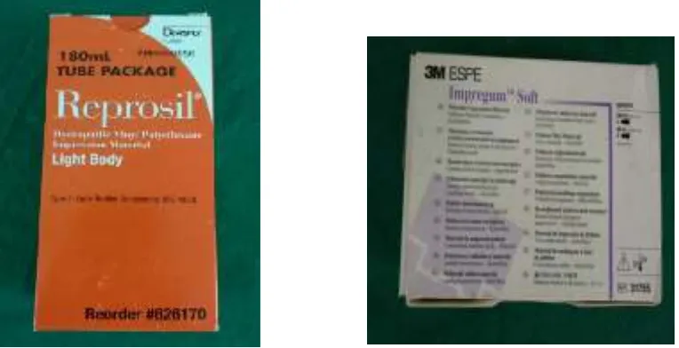
Vinyl polysiloxane impression material, Type 3: light-bodied consistency –
Hydrophilic, Reprosil – Dentsply caulk (fig.1)
Polyether impression material, Type 2: medium-bodied consistency – Hydrophilic,
3M ESPE – Impregum soft. (fig.2)
Soft-liner, Tissue conditioner, Acryton, Orthoplast. (fig.3)
Autopolymerizing Polymethylmethacrylate (PMMA), DPI – RR cold cure (fig.4)
Modelling baseplate wax NO.2, The Hindustan dental products (fig.5)
Type III dental stone, kalabhai karson private limited, Mumbai. (fig.6)
Vinyl polysiloxane(A-silicone) duplicating material,Elite Double 8, Zhermack. (fig.7)
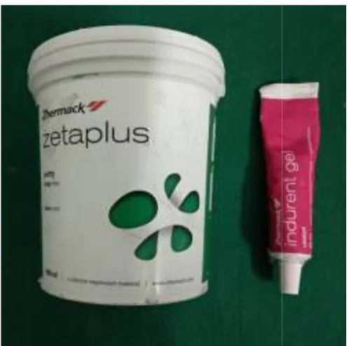
Condensation silicone putty material, Zhermack products.(fig.8)
DEVICES: (fig.9 &10)
Force Sensing Resistor (FSR)- 400, Interlink Electronics.
Printed digital circuit board
Aramentarium : (fig.11&12)
Maxillary Edentulous model
Rubber bowl and spatula
Wax spatula
Wax knife
Wax gauge
Metal gauge
BP handle and blade
Acrylic mixing jar
Duplicating flask
Long bladed mixing spatula
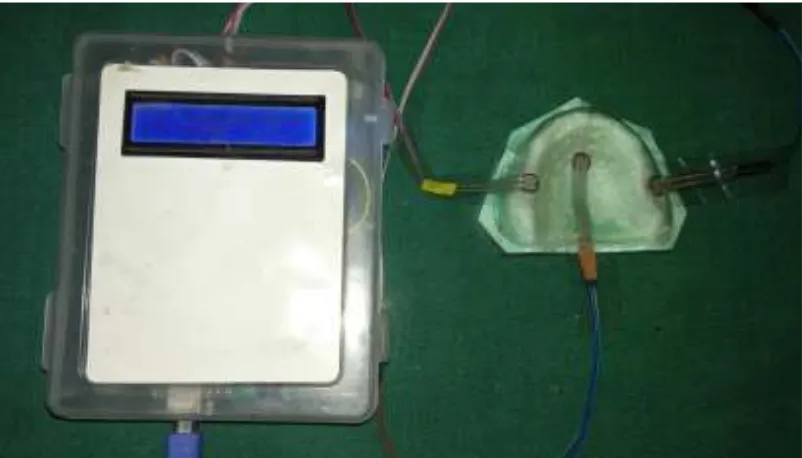
Digitally calibrated pressure sensing device:
The pressure applied on different areas of the denture bearing mucosa was determined using the force sensitive resistor (Model FSR 400).49 The diameter of the active area of resistor was 0.2” (5.00mm) and the thickness was 0.012”(0.3mm). These sensors were connected to electronic components which supports a printed digital circuit board which display the readings achieved, while making secondary impression during the study. (5, 33,52) [fig.9&10]
Fabrication of Edentulous model:
An ideal maxillary edentulous cast was fabricated using type III dental stone, by pouring it into an edentulous mould. The cast was retrieved after its final setting time, according to the manufacturer’s instructions. The maxillary cast thus obtained was trimmed and finished using a model trimmer [fig.11]. A uniform thickness of 2mm baseplate wax was adapted to the denture supporting area on the maxillary cast and then a conventional flasking and dewaxing was done [fig.13&14]. After, the dewaxing procedure, as a separating medium petroleum jelly was applied throughout the mould space, and a uniform mix of softliner was packed inside the mould space. After the final set (5 min 30 sec), the flask was separated and a uniform (2mm) layer of soft liner(16,52) was fabricated using the packing method, which was used along with the cast as a maxillary analog for this study. [fig.15]
Duplication of maxillary analog:
thicknesses. An ‘I’ shaped spacer design(42,49,52) was used in this study with one sheet thickness(41,49,51) and two sheet thickness of base plate wax, respectively(33,47,51,50). A total of twenty trays were fabricated for utilizing the selective pressure technique for the secondary impression procedure.
Fabrication of special trays:
Selective pressure technique(3,6,32) was used for the secondary impression procedure in this study. So, an “I” shape spacer design extending anteroposteriorly from incisive papilla to fovea palatine along the mid palatine raphae region(42,49,50) was used and then the special tray was fabricated over it, using autopolymerizing Polymethyl Methacrylate resin. (29,35,41,42,51) [fig.17&18]
Four rectangular pillars were prepared using PMMA resin and these pillars were trimmed to a desired form and attached to the tray – one each in the right and left premolar crestal region and among the remaining 2 pillars 1 in the anterior midline in the crestal region and 1 in the posterior midpalatine region of the tray. These pillars will act as support for stabilizing the load to be used while on making the secondary impression(4,49). These pillars were duplicated after the desired form was achieved using a Condensation silicone putty index and additional blocks were prepared using this putty index, for the remaining set of trays. [fig.19]
similar thickness of spacer which was used for the impression of one material was used for the other impression material also.
Before impression making, the spacer wax was removed from the special tray and relief holes of uniform diameter of 2mm(4,31,33) were made with a round bur in the relief region and 1 in the crest of the ridge exactly above the region of the sensor(4,10,29,49). Among the 10 samples, for 5 samples the vent holes were placed in the right and for the other 5 trays the vent holes were placed in the left side of the crest of the ridge in relation to the molar region.
Recording the secondary impression:
Under controlled conditions of temperature & humidity, 3 FSR’s (force sensitive resistors) were placed on the maxillary analog. Two sensors were placed over the crest of the ridge, bilaterally in the molar region and one was placed at the centre of the mid palatine raphe region [fig.21] (4,41,49). Two impression materials were used for the secondary impression in this study and they are as follows – Polyether – medium bodied(5,44,48,52) and Vinyl polysiloxane light body impression material(5,29,35,41,44,48,52).
secondary impressions were made with the group of trays with double spacer thickness, with Vinyl polysiloxane and with the same numbered trays the impression was carried out with the polyether impression material, in a sequential manner. [fig.23-26]
Total of forty samples were made as per following distribution
Grouping of samples:
The sensors were positioned as follows: f1 – right crest region, f2 – left crest region, f3 – palatal region. For each samples, three readings at locations f1, f2 and f3 were recorded.
Samples n= 40
GROUP I: Vinyl polysiloxane impression material group
I A: Vinyl polysiloxane impression material with single spacer thickness
I B: Vinyl polysiloxane impression material with double spacer thickness
GROUP II: Polyether impression material group
II A: Polyether impression material with single spacer thickness
II B: Polyether impression material with double spacer thickness
Fig.1 : Vinyl polysiloxane impression material Fig.2 : Polyether impression material
Fig.3: Soft liner, Tissue conditioner
[image:48.595.109.544.427.678.2]
Fig.4: Autopolymerizing Polymethylmethacrylate
Fig.5: Modelling baseplate wax NO.2
Fig.6: Type III dental stone
Type III dental stone Fig.7: Vinyl polysiloxane duplicating material
Fig.8: Condensation silicone putty material
duplicating material
[image:50.595.229.478.405.652.2]Fig.9: Force Sensing Resistor (FSR) – 400
[image:51.595.111.512.424.653.2]Fig.11: Maxillary edentulous model
[image:52.595.123.513.453.707.2]Fig.13: Maxillary edentulous model and 2mm uniform thickness wax spacer after
[image:53.595.115.523.363.494.2]adaptation
Fig.14: Conventional flasking and dewaxing was done
[image:53.595.220.413.580.737.2]Fig.16: Duplication of maxillary analog with soft liner
[image:54.595.338.501.308.458.2]
Fig.17: “I” shaped spacer design Fig.18: Special tray fabrication with pillars
[image:54.595.110.283.310.458.2]
Fig.19: Putty index for fabrication of pillars Fig.20: Metal gauge measuring 2mm
Fig.21: Device along with sensor positioned Fig.22: Digitally readings were acquired
in analog after placing 2kg weight
[image:55.595.347.513.327.502.2]
Fig.23: VPS group with double spacer Fig.24: VPS group with single spacer
[image:55.595.132.298.328.499.2][image:55.595.133.519.559.703.2]
The values of pressure exerted on different areas of a maxillary analog were
tabulated. The pressure sensors were labelled as f1, f2 and f3. These sensors were
positioned as follows: f1- right crest region, f2- left crest region, f3- palate region.
Comparison of two groups
Student’s “t” test for two independent groups was used to compare the significance of
difference between two groups at 5% level of significance.
Note 1: If “p” value is more than 0.05, then we can conclude that there is no
significant difference between the two groups, considered with regard to mean.
Note 2: If “p” value is less than 0.05, then we can conclude that there is a significant
difference between the two groups, considered with regard to mean.
Comparison of more than two groups
Analysis of variance (ANOVA) test was used to compare the significance of
difference between more than two groups at 5% level of significance.
Note 1: If “p” value is more than 0.05, then we can conclude that there is no
significant difference between the two groups, considered with regard to mean.
Note 2: If “p” value is less than 0.05, then we can conclude that there is a significant
difference between the two groups, considered with regard to mean.
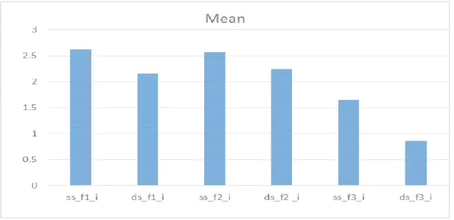
COMPARISON BETWEEN SINGLE SPACER AND DOUBLE SPACER
THICKNESS (INITIAL PRESSURE) IN VINYL POLYSILOXANE GROUP
[ss- single spacer silicone, ds- double spacer silicone, i-initial pressure, f1- right crest
region, f2- left crest region, f3- palate region]
VAR00007 N Mean Std. Deviation
Std. Error Mean ss_f1 _i 10 2.615 0.28818 0.09113 ds_f1 _i 10 2.156 0.60434 0.19111 ss_f2 _i 10 2.567 0.18288 0.05783 ds_f2 _i 10 2.244 0.25413 0.08036 ss_f3 _i 10 1.655 0.27496 0.08695 ds_f3 _i 10 0.863 0.23372 0.07391
Table 1: Group statistics for initial pressure of both spacer thickness in VPS group
Graph 1: Comparision between mean values of initial pressure exerted in both sapcer
thickness of VPS group
[image:57.595.156.474.336.490.2]
Table 2: Statistical analysis for Comparision of initial pressure exerted in both sapcer thickness of VPS group
t df
Sig. (2-tailed)
Std. Error Difference
95% Confidence Interval of the Difference
Inference: Since the p value for f1, f2, f3 region for initial pressure of both the single
spacer and double spacer thickness for vinyl polysiloxane material is less than 0.05, it
can be concluded that there is a significant difference between these two spacer
thicknesses.
From the mean difference it was evident that the initial pressure exerted for double
spacer thickness is less when compared to single spacer thickness for vinyl
polysiloxane material
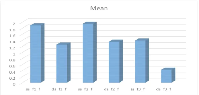
COMPARISON BETWEEN SINGLE SPACER AND DOUBLE SPACER
THICKNESS (FINAL PRESSURE) IN VINYL POLYSILOXANE GROUP [ss-
single spacer silicone, ds- double spacer silicone, f –final pressure, f1- right crest
region, f2- left crest region, f3- palate region]
VAR00007 N Mean Std. Deviation
[image:58.595.143.490.542.709.2]Std. Error Mean ss_f1_f 10 1.887 0.22076 0.06981 ds_f1_f 10 1.255 1.04134 0.3293 ss_f2_f 10 1.941 0.29187 0.0923 ds_f2_f 10 1.35 0.46275 0.14633 ss_f3_f 10 1.389 0.33271 0.10521 ds_f3_f 10 0.424 0.28695 0.09074
Table 3: Group statistics for final pressure of both spacer thickness in VPS group
t
df
Sig. (2-tailed)
Std. Error Difference
95% Confidence Interval of the Difference
[image:59.595.131.501.70.201.2]Lower Upper ss_f1_f 1.877 18 0.077 0.33662 -0.07521 1.33921 ds_f1_f 1.877 9.807 0.090 0.33662 -0.12003 1.38403 ss_f2_f 3.416 18 0.003 0.17301 0.22752 0.95448 ds_f2_f 3.416 15.182 0.004 0.17301 0.22263 0.95937 ss_f3_f 6.946 18 0.000 0.13894 0.6731 1.2569 ds_f3_f 6.946 17.62 0.000 0.13894 0.67265 1.25735
Table 4: Statistical analysis for Comparision of final pressure exerted in both sapcer
thickness of VPS group
Inference: Since the p values for f2, f3 regions at final pressure of both the single
spacer and double spacer thickness for vinyl polysiloxane material was less than 0.05,
it can be concluded that there is a significant difference between these two spacer
thicknesses in f2- left crest region and f3- palatal region. But for the f1- right crest
region, the final pressure exerted for both the spacer thicknesses was not statistically
significant. Although there is a difference in the mean for f1, it was not statistically
significant. From the mean difference it was evident that the final pressure exerted
for double spacer thicknesses is less when compared to single spacer thickness for
vinyl polysiloxane material.
COMPARISON BETWEEN SINGLE SPACER AND DOUBLE SPACER
THICKNESS (INITIAL PRESSURE) IN POLYETHER GROUP [sp- single
spacer polyether, ds- double spacer polyether, in- initial pressure, f1- right crest
region, f2- left crest region, f3- palate region]
VAR00007 N Mean Std. Deviation
Std. Error Mean
spf1_in 10 3.034 0.57225 0.18096 dpf1_in 10 2.679 0.40204 0.12713 spf2_in 10 3.124 0.52109 0.16478 dpf2_in 10 2.066 0.59846 0.18925 spf3_in 10 2.163 0.17827 0.05637 dpf3_in 10 1.592 0.12246 0.03872
[image:59.595.167.474.645.745.2]Graph 3:Comparision between mean values of initial pressure exerted in both sapcer
thickness of PE group
t df Sig. (2-tailed)
Std. Error Difference
95% Confidence Interval of the Difference
Lower Upper
spf1_in 1.605 18 0.126 0.22116 -0.10963 0.81963
dpf1_in 1.605 16.144 0.128 0.22116 -0.11349 0.82349
spf2_in 4.216 18 0.001 0.25094 0.5308 1.5852
dpf2_in 4.216 17.666 0.001 0.25094 0.53008 1.58592
spf3_in 8.349 18 0.000 0.06839 0.42731 0.71469
[image:60.595.133.497.72.254.2]dpf3_in 8.349 15.947 0.000 0.06839 0.42598 0.71602
Table 6: Statistical analysis for Comparision of initial pressure exerted in both sapcer
thickness of PE group
Inference: since the p value for f2- left crest region, f3- palatal region for initial
pressure of both the single spacer and double spacer thickness for polyether material
is less than 0.05, it can be concluded that there is a significant difference between
these two spacer thicknesses. But for the f1- right crest region, there was no
significant difference in the the initial pressure exerted for both the spacer
thicknesses. Although there was a difference in the mean for f1, it was not statistically
COMPARISON BETWEEN SINGLE SPACER AND DOUBLE SPACER
THICKNESS (FINAL PRESSURE) IN POLYETHER GROUP [sp- single spacer
polyether, ds- double spacer polyether, f- final pressure, f1- right crest region, f2- left
crest region, f3- palate region]
N Mean Std.
Deviation
Std. Error Mean
[image:61.595.113.490.184.506.2]spf1_f 10 2.66 0.56864 0.17982 dpf1_f 10 1.988 0.65633 0.20755 spf2_f 10 2.73 0.45646 0.14435 dpf2_f 10 2 0.62732 0.19838 spf3_f 10 2.082 0.09531 0.03014 dpf3_f 10 1.494 0.27097 0.08569
Table 7: Group statistics for final pressure of both spacer thickness in PE group
Graph 4: Comparision between mean values of final pressure exerted in both sapcer
thickness of PE group
t df Sig.
(2-tailed)
Std. Error Difference
95% Confidence Interval of the Difference
[image:61.595.114.517.564.680.2]Lower Upper spf1_f 2.447 18 0.025 0.27461 0.09506 1.24894 dpf1_f 2.447 17.642 0.025 0.27461 0.09422 1.24978 spf2_f 2.976 18 0.008 0.24533 0.21457 1.24543 dpf2_f 2.976 16.444 0.009 0.24533 0.21105 1.24895 spf3_f 6.473 18 0.000 0.09084 0.39716 0.77884 dpf3_f 6.473 11.193 0.000 0.09084 0.38849 0.78751 Table 8: Statistical analysis for Comparision of final pressure exerted in both sapcer
Inference: since the p value for f1, f2, f3 region for final pressure of both the single
spacer and double spacer thicknesses for polyether material was less than 0.05, it can
be concluded that there is a significant difference between these two spacer
thicknesses for polyether impression material. From the mean it was evident that the
double spacer thickness exerted less pressure than single spacer thickness, for
polyether impression material.
COMPARISON OF PRESSURE EXERTED BETWEEN THE GROUP 1: VPS,
AND GROUP 2: POLYETHER, FOR SINGLE AND DOUBLE SPACER
THICKNESSES: [ss- single spacer silicone, ds- double spacer silicone, sp- single
spacer polyether, ds- double spacer polyether, i- initial pressure f- final pressure, f1-
right crest region, f2- left crest region, f3- palate region]
VAR00007 N Mean Std. Deviation Std. Error Mean
[image:62.595.157.476.396.726.2]ssf1_in 10 2.615 0.28818 0.09113 spf1_in 10 3.034 0.57225 0.18096 ssf2_in 10 2.567 0.18288 0.05783 spf2_in 10 3.124 0.52109 0.16478 ssf3_in 10 1.655 0.27496 0.08695 spf3_in 10 2.163 0.17827 0.05637 ssf1_f 10 1.887 0.22076 0.06981 spf1_f 10 2.66 0.56864 0.17982 ssf2_f 10 1.941 0.29187 0.0923 spf2_f 10 2.73 0.45646 0.14435 ssf3_f 10 1.389 0.33271 0.10521 spf3_f 10 2.082 0.09531 0.03014 dsf1_in 10 2.156 0.60434 0.19111 dpf1_in 10 2.679 0.40204 0.12713 dsf2_in 10 2.244 0.25413 0.08036 dpf2_in 10 2.066 0.59846 0.18925 dsf3_in 10 0.863 0.23372 0.07391 dpf3_in 10 1.592 0.12246 0.03872 dsf1_f 10 1.255 1.04134 0.3293 dpf1_f 10 1.988 0.65633 0.20755 dsf2_f 10 1.35 0.46275 0.14633 dpf2_f 10 2 0.62732 0.19838 dsf3_f 10 0.424 0.28695 0.09074 dpf3_f 10 1.494 0.27097 0.08569
Graph 5: Comparison of pressure exerted between the VPS group and Polyether
group for single and double spacer thicknesses
t Sig. (2-tailed) Std. Error Difference
95% Confidence Interval of the Difference
Lower Upper
ssf1_in -2.068 0.053 0.20261 -0.84467 0.00667
spf1_in -2.068 0.059 0.20261 -0.85575 0.01775
ssf2_in -3.189 0.005 0.17464 -0.9239 -0.1901
spf2_in -3.189 0.008 0.17464 -0.94061 -0.17339
ssf3_in -4.902 0.000 0.10363 -0.72571 -0.29029
spf3_in -4.902 0.000 0.10363 -0.72834 -0.28766
ssf1_f -4.007 0.001 0.1929 -1.17826 -0.36774
spf1_ f -4.007 0.002 0.1929 -1.19468 -0.35132
ssf2_f -4.605 0.000 0.17133 -1.14895 -0.42905
spf2_f -4.605 0.000 0.17133 -1.15355 -0.42445
ssf3_f -6.332 0.000 0.10945 -0.92294 -0.46306
spf3_f -6.332 0.000 0.10945 -0.93539 -0.45061
dsf1_in -2.279 0.035 0.22953 -1.00523 -0.04077
dpf1_in -2.279 0.037 0.22953 -1.01045 -0.03555
dsf2_in 0.866 0.398 0.20561 -0.25396 0.60996
dpf2_in 0.866 0.403 0.20561 -0.26939 0.62539
dsf3_in -8.737 0.000 0.08344 -0.9043 -0.5537
dpf3_in -8.737 0.000 0.08344 -0.90846 -0.54954
dsf1_f -1.883 0.076 0.38925 -1.55078 0.08478
dpf1_f -1.883 0.079 0.38925 -1.56183 0.09583
dsf2_f -2.637 0.017 0.24651 -1.1679 -0.1321
dpf2_f -2.637 0.018 0.24651 -1.17115 -0.12885
dsf3_f -8.573 0.000 0.12481 -1.33221 -0.80779
dpf3_f -8.573 0.000 0.12481 -1.33227 -0.80773
Table 10: Statistical analysis for comparison of pressure exerted between the VPS
[image:63.595.107.554.73.269.2]Inference: There was significant difference in the initial pressure exerted in all the
three regions of a maxillary analog except the f1- right crest region for single spacer
thickness of both the groups. Whereas for double spacer thickness of both the groups,
there was significant difference in the initial pressure exerted in all the three regions
of a maxillary analog except the f2- left crest region.
Regarding the final pressure, there was significant difference in the pressure exerted
in all the three regions i.e., f1, f2, f3 of single spacer thickness for both the groups.
Whereas for double spacer thickness, there was no significant difference was found in
the pressure exerted in the f1- right crest region.
From the mean difference between the two groups, it was evident that the vinyl
polysiloxane material group exerted less pressure when compared to Polyether
material group. On the whole, VPS material with double spacer thickness exerted less
pressure when compared to other groups.
COMPARISON OF PRESSURE EXERTED ON THE CREST AREAS TO
EVALUATE IF THERE WAS A SIGNIFICANT DIFFERENCE BECAUSE OF
THE PRESENCE OF VENT HOLES, FOR BOTH THE SPACER
THICKNESSES, OF VPS AND POLYETHER GROUPS:
[sds – single and double spacer silicone, sdp- single and double spacer polyether , i-
gr N Mean Std. Deviation Std. Error Mean
sds_in 1 20 2.204 0.38343 0.08574 2 20 2.587 0.34302 0.0767
sds_f 1 20 1.171 0.61826 0.13825 2 20 2.0455 0.30614 0.06845
sdp_in 1 20 2.5715 0.54812 0.12256 2 20 2.9765 0.51447 0.11504
sdp_f 1 20 2.0635 0.69379 0.15514 2 20 2.6255 0.50469 0.11285
Table 11: Group statistics for comparision of pressure exerted on the crest region
with vent hole and without vent hole for both the spacer thickness of VPS and PE
group.
1= with vent hole 2= without vent hole
Graph 6: Comparision of pressure exerted on the crest region with vent hole and
without vent hole for both the spacer thicknesses of VPS and PE group.
t Sig. (2-tailed) Std. Error Difference
95% Confidence Interval of the Difference
Lower Upper
sds_in 1 -3.329 0.002 0.11504 -0.61588 -0.15012 2 -3.329 0.002 0.11504 -0.61598 -0.15002
sds_f 1 -5.669 0.000 0.15427 -1.1868 -0.5622 2 -5.669 0.000 0.15427 -1.19061 -0.55839
sdp_in 1 -2.409 0.021 0.16809 -0.74529 -0.06471 2 -2.409 0.021 0.16809 -0.74533 -0.06467
[image:65.595.120.498.66.210.2]sdp_f 1 -2.93 0.006 0.19184 -0.95036 -0.17364 2 -2.93 0.006 0.19184 -0.95157 -0.17243
Table 12: Statistical analysis for comparision of pressure exerted on the crest region
with vent hole and without vent hole for both the spacer thicknesses of VPS and PE
[image:65.595.161.476.291.435.2] [image:65.595.107.533.511.677.2]Inference: When comparing the samples with and without vent holes on the crest
areas, there was significant difference for both VPS group and Polyether group, at
initial and final pressure. From the mean it was evident that there was a significant
reduction in pressure in the area of the vent hole when compared to the area without