A potential solution to GMAW gas flow optimisation
S.W. Campbell, A.M. Galloway, G.M. Ramsey
Dept. of Mechanical & Aerospace Engineering, University of Strathclyde, Glasgow G1 1XQ, Scotland, UK [email protected]
N.A. McPherson
BAE Systems Marine - Naval Ships, Glasgow, G51 4XP, Scotland, UK
Abstract
A number of self-regulating shielding gas valves have been developed to synchronise the shielding gas flow rate to the welding current being used in the gas metal arc welding process (GMAW). These valves make claims to reduce the shielding gas consumption by up to 60%. One such system, the Regula® EWR Pro, has undergone detailed evaluation in an effort to fully understand the benefits that could be obtained. This electromagnetically controlled system necessitates around an extremely fast response valve, which opens and closes continually throughout the welding process. This creates a pulsing of the shielding gas, further reducing consumption whilst maintaining optimal shielding gas flow. The unit has been identified to reduce the initial gas surge at weld initiation and results in a virtually instant decay of gas flow at weld termination. These particular characteristics have been found to be ideally suited to saving shielding gas when carrying out intermittent or stitch welding. It was established that the use of this valve generated deeper penetration in fillet welds, which in turn has highlighted the potential to increase the welding speed, therefore further reducing gas consumption. In addition, a computational model has been developed to simulate the effects of cross drafts. The combination of reducing the gas surge and slow decay with faster welding has been shown to meet the drive for cost savings and improving the carbon footprint.
Keywords
GMAW; shielding gas consumption; gas saving devices; improved efficiency; alternating shielding gases; radiography; CFD
Introduction
There is an on-going drive to generate economic savings and reduce the carbon footprint associated with the GMAW process. One area where there is scope to meet these two requirements simultaneously is by optimising the shielding gas flow rate for the welding environment.
Shielding gases are a fundamental component of the GMAW process, its primary purpose to protect the welding region
from contamination by atmospheric gases. There are a number of shielding gases used throughout the world; the welding process, material to be welded and the economic availability of each gas often dictates the shielding gas selected. It is widely known and accepted that the shielding gas has the ability to influence various arc characteristics and consequently the weld geometry and mechanical properties of the solidified joint. Shielding gases are also commonly supplied in a premixed configuration of two or more gases in order to take advantage of the beneficial properties of each gas; the most common shielding gas used in the European shipbuilding industry is an Ar/20%CO2 mixture. As a result,
the shielding gas to be used can be selected to produce a weld of specified geometry using the most economic configuration; Campbell et al. [1] demonstrated with the aid of an artificial neural network that using alternating shielding gases would allow the travel speed to be increased by 28% when compared to Ar/20%CO2 whilst maintaining an equivalent level of
penetration.
The shielding gas flow rate is also known to influence the final weld quality; too low a flow rate can lead to inadequate protection of the welding region, resulting in contamination by atmospheric gases. The potentially detrimental effect of insufficient coverage is generally overcome by selecting a higher shielding gas flow rate. Conversely, too high a flow rate can lead to turbulence in the shielding gas column thus drawing in atmospheric gases [2]; hence there is an optimum shielding gas flow rate. Due to the intense heat in the arc column, the atmospheric gases are dissociated, absorbed into, and spread throughout the weld pool. Porosity is formed in the weld when the buoyancy effects are insufficient to allow the gases to escape from the liquid metal, resulting in gas bubbles becoming trapped, thus creating voids within the solidified joint.
no more than 12 times the filler wire diameter. In addition, a techno-economic evaluation [8] has shown that the shielding gas flow rate can be reduced to 6 L/min in an ideal environment promoting savings of approximately 60% when compared to the 15 L/min base case. The same study also determined that reducing the shielding gas flow rate resulted in a greater level of penetration in the fillet weld setup. Additionally, the use of an electromagnetic shielding gas regulator resulted in further increases in penetration, which were attributed to the pulsing effect produced by the unit and consequently resulted in a periodic peak in arc pressure. A number of electromagnetic gas regulating devices have been developed that claim to reduce the shielding gas consumption by approximately 60% [9-12]. These units generally have built in surge suppression to eliminate the initial peak in shielding gas flow rate due to a build up in line pressure. This surge at weld initiation can be deleterious to weld quality as a result of inducing turbulence in the shielding gas column [2,7]. In addition, these regulators control the shielding gas flow rate according to a relationship derived connecting shielding gas flow rate and welding current; higher current requiring greater flow rates. The flow rate set using a conventional flow meter (or with a mechanical anti-surge device installed) is normally sufficiently high taking into account the highest welding current being used and consequently results in a gross over usage of gas.
The optimal shielding gas flow rates discussed previously and the potential saving claims are often derived under ideal conditions, i.e. assumes that there are no drafts in the welding region. Due to the density of the shielding gas, argon being denser than air, the shielding gas effectively displaces the air from the welding region and blankets the weld metal in the downhand position. When using shielding gases that are lighter than air, i.e. helium, a higher flow rate is often required due to its inability to create a blanket effect. Conversely, the scenario is reversed when welding in the overhead position. Drafts in the welding region therefore present a significant problem to the welding process, potentially displacing the shielding gas from the welding region, thus exposing or partially exposing the weld metal atmospheric gases.
There is very little published data on the effects cross drafts have on the shielding gas coverage. Computational fluid dynamics (CFD) has been used [13] to model the effects that cross drafts and nozzle outlet diameter have on the shielding gas columns effectiveness. It has been determined that by reducing the nozzle outlet diameter the shielding gas column becomes more resistant to the effects of cross drafts. This was attributed to conservation of mass which results in a faster exit velocity allowing lower shielding gas flow rates to be implemented.
It has been determined [8] that the shielding gas flow rate can influence the efficiency of the heat transfer to the parent material with a reduction in shielding gas flow rate resulting in, higher peak temperature, increased penetration and increased distortion. By using faster travel speeds the negative effects can be eliminated and improved productivity would be the outcome.
This is of particular interest to the manufacturing industry, which is moving towards increasingly thinner plate to reduce
the overall mass of the structure with the aim of improving the efficiency of the structure; 4 and 5 mm thick plate is being evermore extensively used in the shipbuilding industry. It is however acknowledged that thinner plate is more susceptible to weld induced distortion due to the lower stiffness of the material. Distortion is introduced to the structure a result of the non-uniform expansion and contraction of the weld metal and can be classified into categories of in-plane and out-of-plane distortion. However, within these categories there are a number of modes of distortion [14-15]; out-of-plane distortion has the potential to adversely affect the accuracy of assembly fit-up [15-16] and occurs when the longitudinal residual stress exceeds the critical buckling strength of the structure [15,17-18]. Whilst there are methods to reduce post-weld distortion to acceptable levels, these are highly resource intensive and do not add value to the final product. Therefore, there is a continual requirement to eliminate as much distortion at source as possible.
Recently, there has been some positive research [3,19] into reducing weld-induced distortion using alternating shielding gases. This is a relatively new method of discretely supplying two different shielding gases, to date, argon (or argon based mixtures) and helium, to the welding region at a predefined frequency in order to take advantage of the beneficial properties of each gas. Different flow vectors are produced in the molten weld pool when different gas shields are present, in addition, three other effects can be attributed to the process: arc pressure peaking, arc pressure variation and variation in weld pool fluidity. The alternating gas method has been reported to reduce the level of porosity present in the solidified weld; this has been attributed to a dynamic action within the weld metal, generated by the three aforementioned effects. Furthermore, the alternating gas process results in greater penetration and improves the melting efficiency of the process; consequently increased travel speeds can be permitted, ultimately reducing the heat input and consequently distortion.
Although it has been determined that the shielding gas flow rate can successfully be lowered to 6 L/min without adversely effecting weld integrity [8], it has also been shown that a lower flow rate is more susceptible to the detrimental effects associated with cross drafts [13]. Therefore extensive trials have been conducted to evaluate the shielding gas flow rate required when a specific cross draft velocity is present, and the effect, if any, that the pulsing effect associated an electromagnetic gas saving device has on the weld quality. The experimental data generated was then used to validate a CFD model. In addition, the resistance of alternating shielding gases to the effects of cross drafts is at an early stage of evaluation.
Experimental Work
Table 1: Chemical composition of parent plate and filler wire
Element Parent Material DH36 steel Welding Consumable 1.2 mm Flux Core
Carbon 0.15 0.04
Silicon 0.35 0.41
Manganese 1.38 1
Phosphorous 0.013 0.01
Sulphur 0.012 0.008
Chromium 0.017(trace) - Molybdenum 0.001(trace) - Nickel 0.018(trace) -
Aluminium 0.026 -
Copper 0.01(trace) -
Niobium 0.025 -
Nitrogen 0.003 -
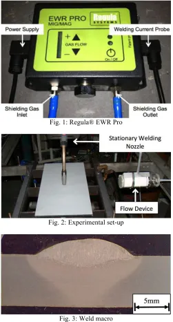
The gas saving device used throughout experimentation was the Regula® EWR Pro, an electronic welding regulator, shown in Fig. 1. This unit is reported to reduce shielding gas consumption by up to 60% through a combination of four mechanisms: a) gas flow rate adjusts automatically according to the welding current being used, b) extremely fast valve that opens and closes continually throughout the welding process and has the ability to shut-off the gas flow even at the shortest stoppage in the welding sequence, c) the pulsing effect promotes further gas savings whilst ensuring optimal flow, and d) elimination of the gas surge at weld initiation.
The unit does not display the shielding gas flow rate and instead uses a LED bank which shows the flow rate within a range according to the correlation between welding current and shielding gas flow rate; each welding current has a programmed upper and lower limits for the shielding gas flow rate. In addition, the unit can be programmed and locked by a line manager which means that the welding operator cannot change the flow rate, which negates the mindset that more gas means better protection.
The shielding gas used throughout experimentation was Ar/20%CO2. Separate trials were performed using a
conventional flow meter and the Regula® EWR Pro to regulate the shielding gas flow rate; in each case the flow rate was monitored and recorded using a dedicated welding monitor. A portable arc monitoring system was used to accurately obtain the welding arc voltage and current; nominal parameters of 24.7 V and 210 A respectively were used throughout.
Trials were performed upon an automatic welding rig (Fig. 2), which held the plate rigid whilst moving at a pre-set speed under a stationary welding torch, in this case a constant travel speed of 3.2 mm/s was used throughout, a cross-section of the weld produced using these parameters is shown in Fig. 3. Thermal data was collected through the use of thermocouples and thermal imaging for the heat transfer validation of the CFD model.
Fig. 1: Regula® EWR Pro
Fig. 2: Experimental set-up
Fig. 3: Weld macro
A flow device (containing a diffuser and a flow straightener) was used to produce a steady, uniformly distributed, laminar cross draft at its output. The flow device was positioned such that the nozzle centre was located 300 mm from the outlet and at an angle 90° to the direction of travel, as shown in Fig. 2. The velocity of the cross draft was measured using a hot wire anemometer in the throat between the nozzle and plate at a height of 5 mm above the surface.
For the latter trials involving alternating shielding gases, the shielding gases used were Ar/20%CO2 and helium, the flow of
[image:3.612.39.287.66.236.2]CFD Model Generation
Due to the transparent nature of the shielding gas, the flow distribution is extremely difficult to visualize, a potential solution to the shielding gas visualisation problem is through the use of CFD.
The flow of any fluid is governed by three fundamental principles: conservation of mass, conservation of energy and Newton’s second law (i.e. force = mass x acceleration). These can then be expressed in terms of mathematical equations which are solved computationally using an iterative process until the final numerical description has converged to within a pre-set criteria. CFD has the ability to predict fluid flow, heat transfer and chemical reactions making it ideal for the prediction of the shielding gas flow and heat transfer in the welding process.
A multi-physics, 3D transient state model was developed [13] using the CFD software Fluent, with the model geometry first being constructed in Gambit to replicate the set-up of the experimental trials using a bottom-up approach. The overall model was designed to be of sufficient volume to ensure that all flow development of interest could be captured. A simplification of the welding arc plasma was assumed using a 12 mm diameter hemisphere positioned directly below the nozzle with an interface being defined between the hemisphere and the plate surface. While it is accepted that the arc plasma interactions are far more complex than this assumption and hence not accounted for in the CFD model, the results discussed later show a good correlation with the experimental trials. Finally, the boundary layers and zones were defined before meshing the model using tetrahedral elements.
The mesh was imported to Fluent where the dynamics of the system were defined. In order to include the heat transfer from the welding arc plasma to the plate, the energy equation was initiated. The heat transfer was modelled using a combination of convection and radiation. The temperature of the arc plasma was determined using the peak arc temperature of approximately 24,000 K for argon at 200 A determined by Jönsson et al. [20] as a starting point. Using an iterative approach, the temperature of the arc plasma was increased until the steel plate temperature distribution within the model was the same as that produced during the experimental trials; this occurred at 32,000 K, slightly higher than that of Jönsson et al. although this was to be expected as the addition of CO2
is known to increase penetration indicating a higher arc plasma temperature and the marginally higher welding current used in the experimental trials.
Buoyancy effects were evaluated by defining the gravitational acceleration components, while the k-epsilon turbulence model was used to evaluate the turbulent kinetic energy, rate of dissipation and consequently the turbulent viscosity of the system.
A laminar side draft was introduced by defining a pressure inlet within the fluid volume, in doing so a pressure difference was defined within the model and consequently a flow of air from the pressure inlet, the velocity of which determined using Bernoulli’s equation.
The shielding gas, Ar/20%CO2, was modelled using the
individual gas properties from the materials database, defining the ratio of the gas mixture and applying the rule of mixtures. A mass flow inlet was defined within the nozzle allowing the flow rate to be controlled.
Results and Discussion
Techno-Economic Effects
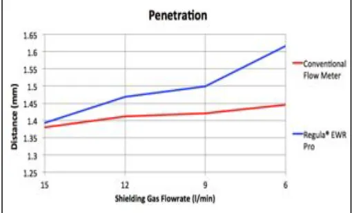
Reducing the shielding gas flow rate provides an obvious economic benefit to the manufacturing community, however weld quality is of paramount importance thus a techno-economic evaluation [8] has been conducted to determine any effect reducing the shielding gas flow rate has on the weld quality in the GMAW process. It has been determined that the shielding gas flow rate can successfully be reduced to 6 L/min in a draft free environment without detriment to weld quality; any porosity present within the weld was well dispersed and of the 2-3 µm region.
[image:4.612.324.579.385.539.2]A number of weld aspects were found to be influenced as a consequence of reducing the shielding gas flow rate which has led to the conclusion that the flow rate affects how efficiently the heat is transmitted to the weld metal, i.e. the thermal efficiency factor. It was observed that a lower shielding gas flow rate produced an increase in penetration in the fillet configuration as shown in Fig. 4.
Fig. 4: Weld penetration
Table 2: Peak temperature (°C) 10 mm from weld centreline Shielding gas
flow rate (L/min)
Conventional flow meter
Regula® EWR Pro
15 630 659
12 646 680
9 720 732
6 743 789
The penetration, distortion and peak temperature correlate with each other and indicate that a faster travel speed could be permitted whilst maintaining weld geometry when welding using a lower shielding gas flow rate. This also suggests that the travel speed could be further increased when welding using the Regula® EWR Pro.
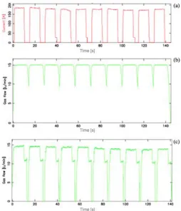
It was also determined that the near instantaneous response of the valve in the Regula® EWR Pro was ideally suited to the stitch (tack) welding process. A series of trials were conducted using a Weldycar NV to automate the process of depositing numerous stitch welds. The Weldycar was programmed to travel at a pre-set speed and perform a series of 50 mm welds with a 50 mm gap, over a 1 m length.
Fig. 5 shows the welding monitor plots of current vs. time and shielding gas flow rate vs. time, when welding with a continuous flow rate of 15 L/min. The periods of time where the current falls to zero (Fig. 5a) indicates when no welding is taking place and is a constant regardless of the shielding gas control method. As can be seen in Fig. 5b, when welding using a conventional flow meter, the shielding gas flow never completely degrades to zero and is therefore consuming unnecessary gas. In contrast, the rapid response of the valve in the Regula® EWR Pro has meant that the unit has had time to purge the line ready to start welding again prior to completely stopping the shielding gas flow (Fig. 5c).
The Regula® EWR Pro was determined to make savings of approximately 20% whilst maintaining the same shielding gas flow rate when welding. In addition to the 20% savings solely attributed to the faster valve are the savings that can be obtained by reducing the shielding gas flow rate, which as previously stated, could be reduced to 6 L/min without detrimentally effecting weld quality which increases the savings possible to approximately 60%.
Experimental Evaluation on the Effects of Cross
Drafts
Weld quality was evaluated using a combination of visual and radiographic examination; due to its ability to detect defects through the thickness of the weld, the results displayed for the experimental trials are those from the radiographic assessment. A grading system was developed to categorise the welds according to the level of defects present; the system allowed for clean welds free from imperfections to pass; isolated (free from harmful) imperfections would return a borderline result whilst welds with greater defect levels would fail. These results are displayed in Fig. 6 using green, yellow and red shading respectively; the number included within each cell is the ratio of cross draft velocity to shielding gas exit velocity.
Fig. 5: Welding monitor plots of (a) current vs. time, (b) shielding gas vs. time (conventional flow meter) and (c)
shielding gas vs. time (Regula® EWR Pro)
Apart from a couple of exceptions, i.e. the borderline results highlighted in yellow, the critical ratio for producing a good quality weld is approximately 2.2 and between 2.2 and 2.4 when using a conventional flow meter and Regula® EWR Pro respectively.
[image:5.612.325.573.534.712.2]This difference in susceptibility to cross drafts between shielding gas control methods is most likely a consequence of the pulsing produced in the shielding gas flow, which momentarily increases the exit velocity of the shielding gas when implementing the same shielding gas flow rate.
CFD Evaluation on the Effects of Cross Drafts
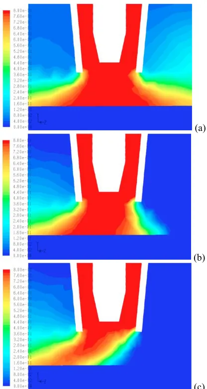
The results were evaluated using contour plots of mass concentration of argon; since the shielding gas modelled was Ar/20%CO2, this method meant that a contour of 80% argon
[image:6.612.347.555.50.441.2]was equal to 100 % shielding gas. The shielding gas column diameters produced when simulating each condition are shown in Fig. 7. In order to generate a grading system for the shielding gas coverage, a weld width of 15 mm was determined using the weld section shown in Fig. 2. This lead to a grading system conditions based upon the shielding gas column diameter as follows: >15 mm produced good coverage (green shading), 10-15 mm reduced coverage (yellow shading) and <15 mm poor coverage (red shading).
Fig. 7: Diameter of shielding gas column determined by CFD
As anticipated, the results followed a pattern showing that as the gas flow rate was increased, the more resistance the shielding gas column had to side drafts. This can be explained using conservation of mass; a higher shielding gas flow rate this means that a higher exit velocity is required to maintain the flow rate, thus reducing the cross draft to shielding gas velocity ratio.
While it is accepted that the flow of various species in the arc column depend on various factors, the results produced using the grading system developed, Fig. 7, are in good agreement to the weld radiographic assessment using a conventional flow meter, Fig. 6. A critical ratio of 2-2.5 has been produced based upon the CFD results compared to the value of approximately 2.2 experimentally determined.
The effect of the cross draft velocity on the shielding gas column can be observed through Fig. 8, which show a constant shielding gas flow rate and increasing cross draft velocity (supplied from right to left). As can be noted, a cross draft velocity of 1 mph has very little effect when using a shielding gas flow rate of 15 L/min, however, when the cross draft velocity is increased to 8 mph, the shielding gas column offers no protection at plate level and consequently resulted in poor coverage as confirmed by the experimental trials.
(a)
(b)
(c) Fig. 8: Flow predicted using CFD for 15 L/min flow rate with
(a) 1 mph, (b) 5 mph and (c) 8 mph cross drafts
The Effects of Cross Drafts on the Alternating
Shielding Gas Process
Preliminary trials have been conducted to determine the effects of cross drafts when using alternating shielding gases at a frequency of 2 Hz. As with the conventional Ar/20%CO2
[image:6.612.37.288.229.310.2]shielding gas mixture, a critical ratio of cross draft velocity to shielding gas velocity has been determined. The critical ratio produced when using alternating shielding gases was determined to be between 1.4-1.6, the results from the radiographic examination are shown in Fig. 9.
[image:6.612.324.576.620.702.2]A comparison of results with the conventional mixture shows that the critical ratio for failure when using alternating shielding gases is far lower than that produced using conventional Ar/20%CO2, with ratios of 1.4-1.6 for alternating
gases and approximately 2.2 for the conventional mixture being produced. This can most likely be attributed to the lower density of helium, which is generally overcome by using a higher shielding gas flow rate. Additionally, the alternating gas mechanism would create turbulence in the gas flow, and while this does not produce an adverse effect when welding in ideal conditions [3,19], the turbulence would result in the intermixing of the cross draft which would ultimately lead to atmospheric gases being spread throughout the weld pool creating porosity and consequently poor weld quality.
Conclusions
Experimental trials have indicated that the shielding gas flow rate can successfully be reduced to 6 L/min without adversely effecting weld quality. This therefore highlights an obvious potential economic benefit to the manufacturing community in which flow rates in the region of 25 L/min are not uncommon. Additionally it was determined that a lower shielding gas flow rate increases how efficiently the heat is transmitted to the weld metal indicating that further savings can be obtained by increasing the travel speed.
A relationship connecting the shielding gas flow rate and cross draft velocity has been developed. This relationship was determined to be that a cross draft velocity to shielding gas velocity ratio of approximately 2.2 is required to produce a good quality weld.
The use of the Regula® EWR Pro has produced marginal increases in the shielding gas columns resistance to cross drafts (producing a velocity ratio of 2.2-2.4) when compared to a conventional flow meter. This has been attributed to the increase in shielding gas velocity due to the pressure impulses as a consequence of the pulsing effect.
The results produced using the simplified arc plasma CFD model are broadly in agreement with the experimental trials according to their respective grading systems producing a critical velocity ratio of 2-2.5, thus highlighting the effectiveness of computational modelling techniques.
The use of alternating shielding gases has been found to reduce the shielding gas column’s resilience to cross drafts in the horizontal welding position; producing a critical ratio of 1.4-1.6. This has been attributed to the density of the shielding gases which means that a higher flow rate of helium would be required to produce equivalent levels of protection.
Acknowledgements
The authors would like to acknowledge the funding provided by BAE Systems Marine - Naval Ships Limited which has made this research possible.
References
[1] Campbell, S.W., Galloway, A.M., McPherson, N.A. “Artificial Neural Network Prediction of Weld Geometry Performed Using GMAW with Alternating Shielding Gases,” Welding Journal, In Press.
[2] Uttrachi, G.D. “GMAW Shielding Gas Flow Control Systems,” Welding Journal, Vol. 86, No. 4 (2007), pp. 22-23.
[3] Campbell, S.W., Galloway, A.M., McPherson, N.A. “Techno-Economic Evaluation on the Effects of Alternating Shielding Gases for Advanced Joining Processes,” Proceedings of IMechE Part B: Journal of Engineering Manufacture, Vol. 225 (2011), pp. 1863-1872. DOI: 10.1177/0954405411408353.
[4] Gillies, A., Galloway, A.M., McPherson, N.A. “Helium Additions to MIG Shielding Gas - An Economic Option?” Welding and Cutting, Vol. 10, No. 2 (2011), pp. 118-121. [5] Weber, R. “How to Save 20% on Welding Costs.
Trailer-Body Builders,” Vol. 44, No. 3 (2003).
[6] Standifer, L.R. “Shielding Gas Consumption Efficiency. The Fabricator,” Vol. 30, No. 6 (2000).
[7] Loxton Industries. “New Welding Gas Innovation,” Australasian Welding Journal, Vol. 55, No. 1 (2010), pp. 10-11.
[8] Campbell, S.W., Galloway, A.M., McPherson, N.A. “Techno-Economic Evaluation of Reducing Shielding Gas Consumption in GMAW whilst Maintaining Weld Quality,” International Journal of Advanced Manufacturing Technology, In Press. DOI: 10.1007/s00170-012-3961-2.
[9] Stauffer, H.V. “Apparatus and Method for Reducing the Waste of Welding Gas,” (1982) US Patent Number 4,341,237.
[10] Hanby, S.K. “Apparatus and Method for Preventing Gas-Surge in a Welding Gas Delivery System,” (2002) US Patent Number 6,390,134,B1.
[11] Uttrachi, G.D. “Welding Shielding Gas Saver Device,” (2003) US Patent Number 6,610,957,B2.
[12] Uttrachi, G.D. “Welding Shielding Gas Saver Flow-Control Device,” (2006) US Patent Number 7,015,412,B1.
[13] Ramsey, G.M., Galloway, A.M., Campbell, S.W. and McPherson, N.A., Scanlon, T.J. “A Computational Fluid Dynamic Analysis of the Effect of Side Draughts and Nozzle Diameter on Shielding Gas Coverage During Gas Metal Arc Welding,” Journal of Materials Processing Technology, In Press.
[14] Conrardy, C., Huang, T.D., Harwig, D., Dong, P., Kvidahl, L., Evans, N., Treaster, A. “Practical welding techniques to minimise distortion in lightweight ship structures,” Journal of Ship Production, Vol. 22, No. 4 (2006), pp. 239-247.
[15] Bhide, S.R., Michaleris, P., Posada, M., DeLoach, J. “Comparison of buckling distortion propensity for SAW, GMAW, and FSW.,” Welding Journal, September 2006 Supplement (2006), pp. 189-195.
Computational Materials Science, Vol. 43 (2008), pp. 353-365.
[17] Tsai, C.L., Park, S.C., Cheng, W.T. “Welding distortion of a thin-plate panel structure,” Welding Journal, May 1999 Supplement (1999), pp. 156-165.
[18] McPherson, N.A. “Thin plate distortion – the ongoing problem in shipbuilding,” Journal of Ship Production, Vol. 23, No. 2 (2007), pp. 94-117.
[19] Campbell, S.W., Galloway, A.M., McPherson, N.A., Gillies. A. “Evaluation of Gas Metal Arc Welding with Alternating Shielding Gases for use on AA6082T6,” Proceedings of IMechE Part B: Journal of Engineering Manufacture, In Press.