ii
STEPPER MOTOR DRIVE USING PIC CONTROLLER
FILZAH BINTIB ABU KASIM
MAY 2009
iii
―I hereby declared that I have read through this report and found that it has comply the partial fulfillment for awarding the degree of Bachelor of Electrical Engineering (Power Electronic and Drive)‖
iv
STEPPER MOTOR DRIVE USING PIC CONTROLLER
FILZAH BINTI ABU KASIM
This Report Is Submitted In Partial Fulfillment Of Requirements For The Degree of Bachelor In Electrical Engineering (Power Electronic and Drive)
Fakulti Kejuruteraan Elektrik
Kolej Universiti Teknikal Kebangsaan Malaysia
v
―I hereby declared that this report is a result of my own work except for the excerpts that have been cited clearly in the references.‖
vi
ACKNOWLEDGMENT
Alhamdulillah, I‘m so grateful to God becauce I had finished my final year profect report. Here, I want to gratitude to all people that concern in cause to succeed my report.
First of all, I want to express my sincere appreciation for my supervisor, Prof Madya Dr, Ismadi Bugis for his patience and kindness for allowing me to do my final year project under his supervision and for his support through this project.
I want to thank all my lectures of Electrical Engineering who keep encourage me to do this final year project.
Unforgetting to gratitude my parent for always give me the support and encourage me for all the time.
vii
ABSTRACT
viii
ABSTRAK
ix
TABLE OF CONTENT
CHAPTER TILTE PAGES
SUPERVISOR‘S DECLARATION TITLE OF THE PROJECT
DECLARATION ii
ACKNOWLEDGEMENT iii
ABSTRACT iv ABSTRAK v
TABLE OF CONTENT vi
LIST OF TABLE x
LIST OF FIGURES xi LIST OF APPENDIX xiii
1 INTRODUCTION
1.1 Introduction 1
1.2 Objective 1
1.3 Scope of The Project 1
1.4 Problem Statement 2
1.5 Methodology 2
1.6 Thesis Outline 3
1.7 Summary 3
2 LITERATURE REVIEW
2.1 Introduction 4
2.2 Stepping System
x
2.2.2 Stepper Drive 5
2.2.3 Stepper Motor 5 2.3 About The Stepper Motor 2.3.1 History of Stepper Motor 6 2.3.2 Definition of Stepper Motor 11
2.3.3 Step Size 12
2.4 Stepper Motor Drive 2.4.1 Characteristic 12
2.4.2 Stepper Motor Drive Technology Review 2.4.2.1 Ministep System 16
2.5 Microcontroller 2.5.1 History of Microcontroller 17
2.5.2 Definition of Microcontroller 17
2.5.3 The Basic Element In The Microcontroller (PIC) 18
2.5.4 PIC (Peripheral Interface Controller) 18
2.6 The C Programming Language 2.6.1 History of C Programming 19
2.7 Summary 20
3 THEORY AND DESIGN 3.1 Introduction 21
3.2 Stepper Motor 3.2.1 The Differents Between Stepper Motor and Servo Motor 22
3.2.2 The Advantages of Stepper Motor 23
3.3 Select PIC 23
3.4 PIC 16F877A Microcontroller 24
3.4.1 Assemble the PIC16F877A 25
3.5 Proteus 6 Lite 27
xi
3.6 MicroC Compiler for PIC Microcontroller 28 3.6.1 Features of The MicroC Compiler 28 3.7 Microsoft Visual C++ 2008 Express Edition 29
3.8 List of Component 30
3.9 Description of component 30
3.10 Summary 35
4 RESULT AND DISCUSSION
4.1 Introduction 36
4.2 Result of the project 36
4.3 The program That Created From The MicroC Compiler
4.3.1 The Program for LED Blinking 39
4.3.2 The Program for Running the Stepper Motor 40 4.4 Download the Program into PIC16F877A using
Winpic800 software 42
4.5 The program that created in Microsoft Visual C++
2008 Express Edition 45
4.6 Simulation Block for Stepper Motor controller 52
4.7 Discussion 56
4.8 Summary 57
5 CONCLUSION AND RECOMMENDATION
5.1 Conclusion 58
xii
REFERENCES 59
xiii
LIST OF TABLES
NO TITLE PAGES
2.1 Combination and the Effect on the magnetic properties of the two pole 7 2.2 The Sequence for Switching the Poles 9 2.3 The Sequence for Swithing the Poles in Half Step Mode 10 3.1 The Different Between Stepper Motor and Servo Motor 22
3.2 Pin Description of PIC16F877A 25
3.3 List of Components 30
3.4 The Parallel Port Signal Lines 34
xiv
LIST OF FIGURES
NO TITLE PAGES
1.1 Flow Chart for Project Methology 2
2.1 The Stepper Motor 6 2.2 Two Magnetic Poles Created When a Wire Coil Around a Magnet 6 2.3 The Magnetic Properties of the Two Magnets 7 2.4 The Opposite Poles Created When the Signal is Reversed 7 2.5 Four Pole Stepper Motor 8 2.6 Stepper Motor Operating in The Half Step Mode 9 2.7 Stepper Drive Element 12 2.8 Basic Unipolar Drive 13
2.9 PIC Microcontroller 16
2.10 The Element in the Microcontroller 18
3.1 The Circuit Design Using Proteus ISI 6 Lite 21
3.2 PIC16F877A Microcontroller 24
3.3 Pin of PIC16F877A 25
3.4 Proteus ISIS 6 Lite Software 27
3.5 MicroC Compiler Software 28
3.6 Microsoft Visual C++ 2008 Express Edition 29
3.7 Push Button 30
3.8 5V Voltage Regulator 31
3.9 20 MHz Crytal Oscillator 31
3.10 ULN2803 32
xv
3.12 Paralel Port 33
3.13 The Pin Outs of Parallel Port (DB25) 33
3.14 Printer Port Base Address 35
4.1 The simulation circuit of Stepper Motor Drive using PIC16F877A 36
4.2 The circuit on Stripe Board 37
4.3 Test the PIC circuit with LED 37
4.4 The LED(Red) for power supply is ON 37
4.5 The Green LED is ON 38
4.6 Testing the PIC circuit with LED Blinking 38
4.7 The program created to test LED blinking 39
4.8 Winpic800 software 42
4.9 Winpic800 software- Hardware test 42
4.10 Winpic800 software- Detect PIC 43
xvi
LIST OF APPENDIX
NO TITLE PAGES
A Gantt Chart for the project 60
B PIC16F87XA Data Sheet 61
xvii
CHAPTER 1
INTRODUCTION
1.1 Introduction
This final year project title is stepper motor drive using PIC controller. These projects are developed to control the stepper motor using the PIC controller. PIC16F877A are used as the controller for the movement of the stepper motor. This PIC16F877A will receive the signal order that programmed from the software.
1.2 Objective
The objectives of this project are:
i. To control the speed, rotating of stepper motor using programming (software). ii. To make sure the stepper motor receive actual order to run properly.
iii. To design the program (software) that controls the stepper motor operation.
xviii
The scopes of this project are:
i. To understand the configuration of stepper motor and PIC Microcontroller. ii. To design the circuit for controlling the stepper motor
iii. To select a suitable PIC Microcontroller for stepper motor controller board.
1.4 Problem Statement
i. Exceeding the rated voltage may shorten the life of the PIC16F877A.
ii. The stepper motor will not turn properly if not receive the correct order from the software.
1.5 Methodology
xix
Figure 1.1 Flow chart for the project methodology 1.6 Thesis Outline
This final report consists of five chapters. First chapter explain about project background including objectives of the project, scope of the project, problem statement, and methodology. Literature Review about the stepper motor and microcontroller are explained in chapter two. Chapter three consists about theory and design of the component and software. Result and discussion are explained in chapter four. Lastly, conclusion and recommendation of the project were explained in chapter five.
1.7 Summary
This chapter is described about objectives, scope of the project, problem statement and methodology and also thesis outline described about all chapters which included in this final report. The literature review about stepper motor, microcontroller and C programming language will be discussed in next chapter.
xx
CHAPTER 2
LITERATURE REVIEW
2.1 Introduction
Before starting for the development project, the research in literature review are been done to improve the knowledge about the project. In this process, all the resources are referred from the books, internet and human resources.
2.2 Stepping System
xxi
2.2.1 Stepper Power Supply
The power supply plays a dual role: it supplies the main power to the motors as well as the power to optically-isolated digital inputs. The motor power is typically provided by a linear non-regulated power supply. Also, the digital interface between the drive and the controller should be powered by the isolated +5 VDC (500 mA max) regulated output. The motor power and the digital interface power are typically isolated since the motor power source is extremely noisy when loaded. Using the motor power for the interface might lead to false pulse commands thereby creating undesired system movement.
2.2.2 Stepper Drive
The drive translates the pulse and direction commands from the controller and converts them into actual motor movement. For each pulse from the controller, the drive will move the motor "one step" in the direction indicated by the direction command. The drive provides 4 different step resolutions for use in a wide range of applications. This drive enables an on-board indexer that moves the motor 1/2 revolution back and forth in half-step mode so the user can easily move the system while troubleshooting. An idle current cutback feature can be used to save power and reduce heat by cutting the power to the motor by 50% if no step pulses are received for 1 second. No software or external resistors are required to configure the drive.
xxii
The motor converts the power from the drive into rotational movement. Unlike AC motors, Stepper Motors have 100% current (idle-current cutback disabled) applied to them all the time regardless of load on the motor. The motor is moved in "steps" (one per command pulse) and will hold at its present position if no command pulses are received. The stepper motor has 4 lead which it easy to connect to driver. Another stepper motor also has 6 or 8 leads, which can cause confusion while wiring the system.
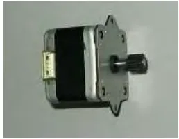
[image:21.612.264.393.270.370.2]2.3 About The Stepper Motor
Figure 2.1 The stepper motor
2.3.1 History of Stepper Motor
xxiii
Figure 2.2 Two magnetic poles created when a wire coil around a magnet
[image:22.612.138.518.182.268.2]The two magnets that shown below are electrically connected with a wire "A1" and "A2". Figure 2.3 shows the magnetic properties of the pair if 5V is applied to A1 and A2 is grounded.
Figure 2.3 The magnetic properties of the two magnets
[image:22.612.138.518.379.459.2]If the signal is reversed, and "A2" has 5V applied to it while "A1" is grounded then opposite poles will be created. This is shown in Figure 2.4.
Figure 2.4 The opposite poles created when the signal is reversed
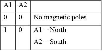
[image:22.612.241.414.624.711.2]A1 and A2 can either be at 5V or ground. This gives us four possible combinations of signals. Table 2.1 shows the combinations and the effect that they have on the magnetic properties of the two poles.
Table 2.1 Combinations and the effect on the magnetic properties of the two poles A1 A2
0 0 No magnetic poles 1 0 A1 = North
xxiv
0 1 A1 = South A2 = North
1 1 No magnetic poles
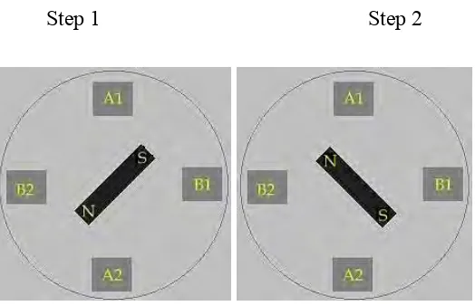
There is no reason to ever use the combination of A1 and A2 both being on at the same time. The same net result can be obtained by both poles being grounded. A stepper motor is a digitally controlled motor that has non-accumulative rotational error. This means that the number of rotations that the motor turns can be accurately controlled and measured. The motor will rotate one step per digital signal change. A step is a fraction of a rotation (resolution) that can be calculated by the 1 / (no. of magnetic poles). An illustration of a 4 pole stepper motor is displayed in Figure 2.5.
[image:23.612.198.460.374.543.2]Step 1 Step 2
Figure 2.5 Four pole stepper motor
xxv
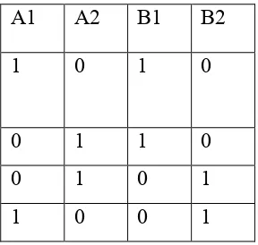
[image:24.612.256.400.221.358.2]If 5V is next applied to A2 and B1, the magnet connected to the shaft will rotate 90° (Step 2). This sequence can be repeated for the next step, the next one after that, and so on. In this example there are four poles and the motor will rotate 25 percent, or 90 degrees, for every step. The sequence for switching the poles is displayed in Table 2.2 below.
Table 2.2 The Sequence for Switching the Poles
A1 A2 B1 B2
1 0 1 0
0 1 1 0
0 1 0 1
1 0 0 1
This is the illustration of a motor operating in a full step mode. Greater resolution can be gained if the motor is rotated half a step at a time. If this mode is selected less torque is generated by the motor. There is less torque because for every half step only one magnet pair is attracting the magnet connected to the shaft. Half steps are created by turning off one pair of poles in between transitions from one step to another. The sequence for switching the poles in a half step mode is displayed in Table 2. 3. Figure 2.6 is an illustration of a stepper motor operating in half step mode.