i
DEVELOP A ROTATING SPEED SENSOR SYSTEM WITH LINK TO VISUAL BASIC.NET
CHEE JIANN TONG
This report is submitted in partial fulfillment of the requirements for the award of Bachelor of Electronic Engineering (Industrial Electronics) with Honours
Faculty of Electronic and Computer Engineering Universiti Teknikal Malaysia Melaka
ii
UNIVERSTI TEKNIKAL MALAYSIA MELAKA
FAKULTI KEJURUTERAAN ELEKTRONIK DAN KEJURUTERAAN KOMPUTER
BORANG PENGESAHAN STATUS LAPORAN
PROJEK SARJANA MUDA II
Tajuk Projek : Develop a Rotating Speed Sensor System with Link to
Visual Basic.Net
Sesi
Pengajian : 2009/2010 Semester 2
Saya CHEE JIANN TONG mengaku membenarkan Laporan Projek Sarjana Muda ini disimpan di Perpustakaan dengan syarat-syarat kegunaan seperti berikut:
1. Laporan adalah hakmilik Universiti Teknikal Malaysia Melaka.
2. Perpustakaan dibenarkan membuat salinan untuk tujuan pengajian sahaja.
3. Perpustakaan dibenarkan membuat salinan laporan ini sebagai bahan pertukaran antara institusi pengajian tinggi.
4. Sila tandakan ( √ ) :
SULIT*
(Mengandungi maklumat yang berdarjah keselamatan atau kepentingan Malaysia seperti yang termaktub di dalam AKTA RAHSIA RASMI 1972)
TERHAD* (Mengandungi maklumat terhad yang telah ditentukan oleh organisasi/badan di mana penyelidikan dijalankan)
Disahkan oleh:
……… (TANDATANGAN PENULIS)
……… (COP DAN TANDATANGAN PENYELIA)
Alamat Tetap: No. 4, Jalan Sungkai, Taman Kawan 35500 Bidor, Perak.
iii
“I hereby declared this report is result of my own effort except for works that have been cited clearly in the references.”
iv
“I hereby declare that I have read this report and in my opinion this report is sufficient in terms of the scope and quality for the award of Bachelor of Electronic
Engineering (Industrial Electronics) with Honours.”
Signature : ……….…
v
vi
ACKNOWLEGEMENT
I wish to express sincere appreciation to Universiti Teknikal Malaysia Melaka (UTeM) for giving me a chance to further my study on Bachelor of Degree in Industrial Electronics in Faculty of Electronics and Computer Engineering (FKEKK).
Despite of that, I would take this opportunity to express my profoundest gratitude and deepest regards to all those who gave me the possibility to successfully complete this PSM. I am deeply indebted to my Project Supervisor Encik Farid Arafat Bin Azidin and I wish to express a million thanks for her exemplary guidance, monitoring and constant encouragement throughout the development of the project.
vii
ABSTRACT
viii
ABSTRAK
ix
TABLE OF CONTENTS
CHAPTER TITLE PAGE
TITLE PROJECT i
PENGAKUAN ii
STUDENT DECLARATION iii
SUPERVISOR’S DECLARATION iv
DEDICATION v
ACKNOWLEDGEMENT vi
ABSTRACT vii
ABSTRAK viii
TABLE OF CONTENT ix
LIST OF TABLES xiii
LIST OF FIGURES xiv
LIST OF APPENDIX xvi
I INTRODUCTION 1
1.1 Project Introduction 1
1.2 Project Objectives 2-3
1.3 Scope of Project 3
1.4 Problem statement 4
1.4.1 Programming Language 4 1.4.2 Interfacing between hardware and software 4 1.4.3 PIC Programmer 4 1.4.4 Reason for select Visual Basic.NET software 4
x
II LITERATURE REVIEW 7
2.1 Introduction 7
2.2 Introduce to tachometer 8
2.2.1 Definition 8
2.2.2 The History and Evolution of the Tachometer 9
2.3 Types of Tachometer 10
2.3.1 Electromagnetic Linear-Velocity Transducer 11
2.3.2 Electromagnetic Vibratory Transducer 11
2.3.3 Toothed Rotor Magnetic Tachometer 12
2.3.4 Electro-optical tachometer 12
2.3.4.1 Reflectance method 12
2.3.4.2 Stroboscopic System 13
2.3.4.3 Transmittance method 13
2.3.5 Strain Gage Tachometer 14
2.3.6 Switch Tachometer 14
2.3.7 Centrifugal Force Tachometer 15
2.3.8 Laser Tachometer 15
2.3.9 Toothed-rotor tachometer 16
2.3.10 Optical Rotary Encoder 18
2.3.11 Infrared Sensor 19
2.4 Comparison 20
2.4.1 Analog and Digital Tachometers 20
2.4.2 Contact and non-contact type Tachometers 20
2.4.3 Time and Frequency Based Measurement 21
xi
2.5 Types of Speed Sensor
2.5.1 Optical Sensing 23
2.5.2 Magnetic Sensing 23
III PROJECT METHODOLOGY 24
3.1 Introduction 24
3.1.1 Method / Procedure Project 25
3.2 Software Development 26
3.2.1 Visual Basic.NET 26
3.2.2 Graphical User Interface (GUI) 26
3.2.3 Program Implementation Process 27
3.3 Hardware Development 28
3.4 PC Tachmeter Circuit 29
3.4.1 PC (Personal Computer) 29
3.4.2 The Power Supply Part 30
3.4.3 The Motor Circuit 31
3.4.4 The Infrared LED Circuit 31
3.4.5 Interfacing Part 32
3.4.6 Voltage measured for PIC16F628 32
3.4.7 Voltage measured for MAX232 33
3.4.8 QRD1113 Reflective Object Sensor 34
3.4.9 The LCD & RPM Counter 35
3.4.10 PIC16F628 36
3.4.11 Programming the PIC16F628A 36
xii
IV RESULT AND ANALYSIS 40
4.1 Introduction 40
4.2 PIC Pro Basic Coding 41-42 4.3 Program the PIC in the ISIS and debugging 43
4.4 Simulation Circuit 44
4.5 GUI's Display 45
4.5.1 Result of speed in deactivate state 45
4.5.2 Result of speed in normal circumstances 45
4.5.3 Result of speed when click start button 46
4.5.4 Result when receive data from hardware 46
4.5.5 Result of speed when click save button 47
4.5.6 Final Result 48
4.5.7 Discussion 49
V CONCLUSION AND RECOMMENDATION 50
5.1 Conclusion 50
5.2 Recommendations 51
xiii
LIST OF TABLE
NO TITLE PAGE
2.4.1 Comparison between analog and digital Tachometers 20 2.4.2 Comparison between contact and non-contact type Tachometers 20 2.4.3 Comparison between time and frequency based measurement 21 2.4.4 Comparison among my project with other types of tachometer 22
xiv
LIST OF FIGURES
NO TITLE PAGE
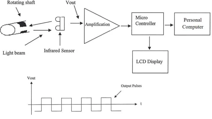
1.1 Block Diagram of a Rotating Speed Sensor System
with Link to Visual Basic.NET 2
2.3 Types of Tachometer 10
2.3.1 Electromagnetic Linear-Velocity Transducer 11
2.3.2 Electromagnetic Vibratory Transducer 11
2.3.3 Toothed Rotor Magnetic Tachometer 12
2.3.4.1 Electro-optical tachometer 12
2.3.4.2 Stroboscopic System 13
2.3.4.3 Transmittance method 13
2.3.5 Strain Gage Tachometer 14
2.3.6 Switch Tachometer 14
2.3.7 Centrifugal Force Tachometer 15
2.3.9 Toothed-rotor tachometer detection 17
2.3.10 Optical Rotary Encoder 18
2.3.11 Infrared sensor detection 19
3.1 Project Methodology 24
3.1.2 The Method Used 25
3.3.1 Block of function circuit and the components that involved 28
3.4.2 Power supply circuit for “PC Tachometer” circuit 30
3.4.3 Motor circuit for “PC Tachometer” circuit 31
xv
3.4.5 Interfacing circuit for rotating speed sensor system circuit 32
3.4.8 Sensor 34
3.4.9 The PIC16F628, MAX232 and LCD circuit 35
3.4.10 PIC16F628A 36
3.4.13.1 Rotating Speed Sensor System PCB Circuit 38
3.4.13.2 RS232 PCB Circuit 39
4.2.1 PIC basic coding 41
4.2.2 PIC basic coding in HEX file 42 4.4 Simulation Circuit using Proteus 44 4.5.1 The display during the ON/OFF switch is OFF 45 4.5.2 The display during the ON/OFF switch is ON 45 4.5.3 The display during the START button is ON 46 4.5.4 The display during the receiving data from the hardware 46 4.5.5 The display during record the speed of rotor 47
xvi
LIST OF APPENDIX
NO TITLE PAGE
A PIC Coding 53-54
1
CHAPTER 1
INTRODUCTION
1.1 PROJECT INTRODUCTION
2
Figure 1.1: Block Diagram of a Rotating Speed Sensor System with Link to Visual Basic.NET
1.2 Project Objectives
The aim of designing and constructing the circuit is to fulfilled several objectives that need to be achieved. Nowadays, sciences and technology is very important to us. Day by day, there a lot of something new and useful has been created. So, this project can be assumed as a contribution to the science and technology if it can be done successfully.
3
There are several objectives that need to be achieved at the end of PSM. The objectives are listed as below:
i. To upgrade the existing project from develop angular speed detection system using infrared sensor to a rotating speed sensor system using infrared sensor with link to Visual Basic.Net.
ii. To develop a graphical user interface (GUI) that can show and record the speed in rev/min of the rotating mechanical device.
iii. To interface the rotating speed sensor system with personal computer by using Visual Basic.Net.
iv. To display the speed value in rev/min on the LCD display and GUI in PC.
1.3 Scope of Project
The scope of this project is to develop a rotating speed sensor system using a special Infra-Red sensor (IR) where it can detect black and white color and give a small differences voltage signal This scope project will cover: a) The input power has used battery 9V-15V.
b) The PIC Controller use in this project is PIC16F628A.
c) The rotation motor speed sensor system will measured around 0 - 4000 revolutions per minute and ± 10% tolerance.
d) The output will display in digital value at 2x8 LCD screen. The screen updates the RPM every 1.5 seconds.
4
1.4 Problem Statement
1.4.1 Programming Language
The PICBASIC software is used to “cross compile” the BASIC code into assembly and it will make the HEX file for you. It’s much easier and is quite powerful.
1.4.2 Interfacing between hardware and software
By using the DB9 connector, the speed value in rev/min can be quickly show on the graphical user interface that i design right after the signal is sent from the hardware. The sampled result can be shown on the Visual Basic.NET front panel in the rapid of time instead.
1.4.3 PIC Programmer
Programming the PIC16F628A is very simple however you need a device called a “PIC Programmer” to do it. It’s a small interface that will connect to your
computer’s serial or parallel port. The PIC chip plugs into the programmer and you load the software (HEX file) into it from the computer.
1.4.4 Reason for select Visual Basic.NET software
5
1.5 Report Structure
This thesis is a documented report of the ideas generated, the theories and concepts applied, the activities performed and the final product of this project produced. The thesis consists of five chapters and each chapter is described as below:
The first chapter is the introduction of a rotating speed sensor system with link to visual basic.Net. The block diagram gave the general ideas on this project. In addition, objectives, problem statement of the project and the report structure is included as well.
The second chapter is the background study of the project along with the literature review is performed and documented about the theoretical concept applied in completing the project. This includes of similar project but use the different method. The project will be explained briefly in this chapter. So it is very important to understand the concepts involve and how this system works.
6
The fourth chapter is about the components used in this project. This chapter gives information about hardware and software involves in order making this project works. This chapter also gives information about a circuit and the main components used. Hardware protoyping and the develop Visual Basic.Net Graphical User Interface (GUI).
The fifth chapter is shows overall result of rotating speed sensor system and discussion of the result as well as the comparison with the covention method. This chapter consists of an outcome for this project. It shows results, possible problems and solution for the problem occurred.
7
CHAPTER 2
LITERATURE REVIEW
In this chapter the various aspects and the methods on research methodology on the proposed project will be studied and analyzed one by one. Past projects and thesis which were related to the proposed project would be referred. Existing related projects will be referred to make the proposed project fulfill the project objectives and outcomes. Besides, this chapter will show the actual concept of rotating speed sensor system. Moreover, the research and comparison that carried out for some type of tachometer that occur at the market.
2.1 Introduce to rotating speed sensor system with link to visual basic.NET
8
2.2 Introduce to Tachometer
2.2.1 Definition
A tachometer is an instrument designed to measure the speed of an object or substance. The word is formed from Greek roots: tachos, meaning speed, and metron, meaning measure. The traditional tachometer is laid out as a dial, with a needle indicating the current reading and marking safe and dangerous levels. Recently, digital tachometers giving a direct numeric output have become more common. It can be used to measure speed of a rotating shaft. Moreover, it can also be used to measure flow of liquid by attaching a wheel with inclined vanes.
In its most familiar form, a tachometer measures the speed at which a mechanical device is rotating. A common example is the tachometer found on automobile dashboards. In this application, the tachometer measures the revolutions per minute (RPMs) of the engine drive shaft. It is important to monitor engine RPMs, as running the engine at excessively high rates can drastically shorten engine life.
A tachometer used in this application can be built in multiple ways. It may be a small generator attached to the engine drive shaft, where the RPM measurement is scaled to the electric current generated by the device. Alternately, it may simply measure the rate at which the ignition system sends sparks to the engine.